GV3M01485-PWireless Presenter
ACCO Brands, Inc.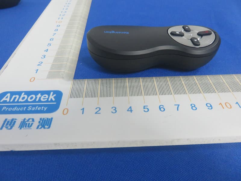
Click to zoom
Application Details
- Equipment Class
- DXT - Part 15 Low Power Transceiver, Rx Verified
- Date of Grant
- Mar 12, 2020
- Application Purpose
- Original Equipment
- Date of Application
- Mar 12, 2020
- Equipment Note
- Wireless Presenter
- Frequency Range
- 2408.00000000 - 2474.00000000
- Company
- ACCO Brands, Inc.
- Country
- United States
Documents & Files
Document Text
Text extracted from the exhibit documents filed with the FCC. Open a document above to read the original.
Users Manual
kensington.com/register Presenter with Red Laser Kensington and the ACCO name and design are registered trademarks of ACCO Brands. All other registered and unregistered trademarks are the property of their respective owners. Covered by one or more of US Pat. No’s 6,081,974; 6,317,936; 6,360,405. ©2019 Kensington Computer Products Group, a division of ACCO Brands. Any unauthorized copying, duplicating, or other reproduction of the contents hereof is prohibited without written consent from Kensington Computer Products Group. All rights reserved. 11/19 901-0034-00K33374 Kensington Computer Products Group A Division of ACCO Brands 1500 Fashion Island Blvd, 3rd Floor San Mateo, CA 94404 ACCO Brands Australia- Kensington 2 Coronation Avenue Kings Park NSW 2148 Australia Importer: LEITZ ACCO Brands GmbH & Co KG Siemensstraße 64 70469 Stuttgart Germany Importado e Distribuído por: TILIBRA PRODUTOS DE PAPELARIA LTDA. CNPJ: 44.990.901/0001-43 Rua Aymorés, 6-9 – Bauru/SP – Brasil CEP 17013-900 [email protected] ACCO Brands Canada Inc 7381 Bramalea Rd Mississauga, ON L5S 1C4 https://accobrandscanada.com Acco Brands Chile S.A., Avda. Presidente Riesco # 5711, oficina 201 Las Condes, Santiago, Chile CP 7561114 www.accobrands.cl 广州市爱珂贸易有限公司 上海分公司 中国上海市长宁区 延安西路2299号1509室 电话뻭021-61368966 传真뻭021-61710161 www.accobrands.cn Импортер: ООО ""Эссельте"", Россия, 125040, Москва, 3-я улица Ямского поля, д.18, тел. +7(495)933-27-63 164-8721 1-32-2 14F https://www.kensington.com/ja-JP E-MAIL: [email protected] ACCO Brands Asia Pte Ltd 5A Toh Guan Road East #06-03, Singapore 608830 Forgalmazza: Esselte Kft, Váci út 76. V. torony I. emelet, 1133 Budapest, Magyarország Distribuitor: Esselte Sales SRL, Gheorghe Ţiţeica 121C, Sector 2, Bucureşti, România Dystrybutor: Esselte Polska Sp. z o.o., ul. Przemysłowa 11A, 26-900 Kozienice Distribútor: Esselte, s.r.o., V Lužích 818, 142 00 Praha 4, Česká republika дистрибьютор: Esselte Polska Sp. z o.o., ul. Przemysłowa 11A, 26-900 Kozienice Импорттаушы: “АБДИ Компани” АК, Алматы к., Сейфуллин данғ. 465/191 Дистриб'ютор: Ессельте Польска Сп. з о.о., вулиця Пшемислова, 11А, 26-900 Ko зеніце Importado por ACCO Mexicana S.A. de C.V. Circuito de la Industria Norte # 6, Corredor Industrial Toluca Lerma, Lerma México Cp. 52004 R.F.C. AME640229-1W3 TA-XXXX/XXXX TA-XXXX/XXXX Este equipamento opera em caráter secundário, isto é, não tem direito a proteção contra interferência prejudicial, mesmo de estações do mesmo tipo, e não pode causar interferência a sistemas operando em caráter primário. 3 English 2 12 65' (20m) max. 20m max. 20 m (65 pieds) maximum Max. 20 m 65' (20 m) máximo 20 m (65') max. 65 pol (20 m) no máximo Maks. 20 m (65’) 20 m (65') maks. 65' (20 m) max. Maks. 20 m Maks. 65' (20 m) 65' (20 m) maks. .أقصى كحد (م 20) '65 Iki 65 pėdų (20 m) Maks. 65' (20m) Max 20 m Max. 20 m Max. 20 m (65') 65' (20m) max. 65' (20m) max. Макс. 65' (20 м) 65' (20 м) макс. 65' (20m) maks. 65' (20 m) μέγ. 3 4 CLASS 2 LASER SAFETY STATEMENT 1. Emission of a parallel beam of visible light; • Do not disassemble the device • Do not use the device outside of its specified operating temperature range. If the device is exposed to an enviroment outside of its prescribed operation, turn off the device and allow the temperature to stabilize within the specified operating range before using the device. CAUTION! A set of warning labels in different languages is provided with this product. It is essential that the correct country-specific warning label is applied to the laser pointer for the safety of the user and of the people nearby. CAUTION! This device has no serviceable parts. Use of controls or adjustments or performance of procedures other than those specified herein may result in hazardous radiation exposure. This laser device complies with International Standard IEC 60825-1:2014 / EN 60825-1:2014, Class 2 Laser Product and also complies with 21 CFR 1040.10 and 1040.11, except for deviations pursuant to laser Notice No.50, dated Jun 24, 2007: 2. Maximum Power of 1 millliwatt CW, wavelength range 650+/-10 namometers; 3. Operating temp between 0° C(32° F) to 40° C(104° F). ATTENTION: LASER RADIATION DO NOT STARE INTO BEAM CLASS 2 LASER PRODUCT WAVELENGTH: 650+/-10nm OPTICAL POWER:<1mW IEC 60825-1:2014 / EN 60825-1:2014 Please select your country specific safety warning sticker and adhere to the laser pointer DEUTSCH CAUTION!IMPORTANT SAFETY INSTRUCTIONS • Never shine a laser pointer into a person's eyes, or stare into the laser beam. Pointing a laser pointer into a person's eyes, or staring directly at the laser beam, can cause instant temporary vision dysfunction such as flash blindness, disorientation or glare. This can be particularly dangerous if the exposed person is engaged in a vision-critical activity such as driving. In addition, prolonged and/or repeated exposure to the laser beam can be hazardous and damaging to eyes. • Never aim a laser pointer anywhere on any or person or animal. Laser pointers are designed to illustrate inanimate objects only. In some states and provinces, it is illegal to aim a laser pointer on a law enforcement officer or on any other person. The purchaser/user is responsible for insuring that his or her use of the laser pointer conforms to any local laws. • Do not point a laser pointer at mirror-like surfaces. A reflected beam can act like a direct beam on the eys. • Laser pointers are not toys. Do not allow a minor to use a pointer unsupervised. In some states and provinces, it is illegal for a minor to purchase and/or use a pointer. The purchase/user is responsible for insuring that his or her purchase or use of the laser pointer conforms to any local laws. The Wireless Presenter with Laser Pointer includes a built-in laser pointer. Therefore, as with any laser pointer, it is important to adhere to the following warnings and safety instructions to prevent injury: VORSICHT! WICHTIGE SICHERHEITSHINWEISE Der kabellose Presenter verfügt über einen integrierten Las…
Text truncated - open the document above for the full version.
External Photos
FCC ID: GV3M01485-P
ID Label/Location Info
Label Location On EUT Label Product Name: Wireless Presenter Model No.: M01485-P FCC ID: GV3M01485-P This device complies with Part 15 of the FCC Rules. Operation is subject to the following two conditions: (1) This device may not cause harmful interference, and (2)This device must accept any interference received, including interference that may cause undesired operation.
Internal Photos
FCC ID: GV3M01485-P ANT
Operational Description
version01 ACCO Brands, Inc. Declaration concerning Antenna Specification It is hereby declared that the product Model No.: M01485-P FCC ID : GV3M01485-P fulfills the requirement in FCC test relating to the antenna type. The device specified above confirms to the FCC recommendations for internal antenna type(s) described below: Model No. of antenna: N/A Type of antenna:PCB Antenna Gain of the antenna: -2 dBi Frequency range:2408~2474MHz The mounting of the antenna is fixed to the radio module and no other antenna should be used. Company name: ACCO Brands, Inc. Address: 1500 Fashion Island Blvd., 3rd Floor, San Mateo, CA94404, United States City: San Mateo, CA94404 ZIP / Postal code: Country:United States Place:United StatesDate: 2020-03-10 Signature:
RF Exposure Info
FCC ID: GV3M01485-P RF EXPOSURE EVALUATION EUT Specification EUT Wireless Presenter Model Name M01485-P Frequency band (Operating) WLAN: 2.412GHz ~ 2.462GHz WLAN: 5.18GHz ~ 5.32GHz / 5.50GHz ~ 5.70GHz WLAN: 5.745GHz ~ 5825GHz Others: 2408‐2474MHz Device category Portable (<20cm separation) Mobile (>20cm separation) Others ___ Antenna diversity Single antenna Multiple antennas Tx diversity Rx diversity Tx/Rx diversity Max. output power 94.38 dBuV/m (-0.877dBm)(0.817mW) Antenna gain -2 dBi Evaluation applied MPE Evaluation SAR Evaluation Standard Requirement Portable Device According to §15.247(i) and §1.1307b(1), systems operating under the provisions of this section shall be operated in a manner that ensures that the public is not exposed to radio frequency energy levels in excess of the Commission’s guidelines. See KDB 447498 D01 General RF Exposure Guidance V6, section 4.3.1. The 1-g and 10-g SAR test exclusion thresholds for 100 MHz to 6 GHz at test separation distances ≤ 50 mm are determined by: [(max. power of channel, including tune-up tolerance, mW)/(min. test separation distance, mm)] ·[√f(GHz)] ≤ 3.0 for 1-g SAR and ≤ 7.5 for 10-g extremity SAR, 16 where ·f(GHz) is the RF channel transmit frequency in GHz ·Power and distance are rounded to the nearest mW and mm before calculation17 ·The result is rounded to one decimal place for comparison The test exclusions are applicable only when the minimum test separation distance is ≤ 50 mm and for transmission frequencies between 100 MHz and 6 GHz. When the minimum test separation distance is < 5 mm, a distance of 5 mm is applied to determine SAR test exclusion. FCC ID: GV3M01485-P Measurement Result Channel Frequency (MHz) Max Output power (dBm) Tune up tolerance (dBm) Max Tune Up Power (dBm) Distance (mm) Calculati on Value (Note 1) Threshold Value 2474 -0.877 ±1 0.123 5 0.32 3.0 EIRP=E-104.8+20logD= 94.38 -104.8+20log3= -0.877dbm Note 1: Calculation Value =[(max. power of channel, included Tune up tolerance, mW)/(min. test separation distance, mm)] ·[√f(GHz)]. Fox example: 1.029/5*√ 2.474=0.32 ≤3.0 According to KDB447498 D01 V6, threshold at which no SAR required is ≤3.0 for 1-g SAR, separation distance is 5mm, and no simultaneous SAR measurement is required. The SAR measurement is not necessary.
Test Report
Report No.: SZAWW191111002-01FCC ID: GV3M01485-PPage 1 of 37 Code:AB-RF-05-a FCC TEST REPORT Client Name: ACCO Brands, Inc. Address: 1500 Fashion Island Blvd., 3rd Floor, San Mateo, CA94404, United States Product Name: Wireless Presenter Date: Mar. 10, 2020 Shenzhen Anbotek Compliance Laboratory Limited Report No.: SZAWW191111002-01FCC ID: GV3M01485-PPage 2 of 37 Code:AB-RF-05-a Contents 1. General Information ............................................................................................................................................... 4 1.1. Client Information ....................................................................................................................................... 4 1.2. Description of Device (EUT) ..................................................................................................................... 4 1.3. Auxiliary Equipment Used During Test ................................................................................................... 5 1.4. Description of Test Modes ........................................................................................................................ 5 1.5. List of Channels .......................................................................................................................................... 6 1.6. Description of Test Setup .......................................................................................................................... 7 1.7. Test Equipment List .................................................................................................................................... 8 1.8. Description of Test Facility ........................................................................................................................ 9 2. Summary of Test Results ................................................................................................................................... 10 3. Conducted Emission Test ................................................................................................................................... 11 3.1. Test Standard and Limit .......................................................................................................................... 11 3.2. Test Setup .................................................................................................................................................. 11 3.3. Test Procedure .......................................................................................................................................... 11 3.4. Test Data .................................................................................................................................................... 12 4. Radiated Emission and Band Edge .................................................................................................................. 13 4.1. Test Standard and Limit .......................................................................................................................... 13 4.2. Test Setup .................................................................................................................................................. 14 4.3. Test Procedure .......................................................................................................................................... 15 4.4. Test Data .................................................................................................................................................... 16 5. 20dB Bandwidth Test .......................................................................................................................................... 26 5.1. Test Standard and Limit .......................................................................................................................... 26 5.2. Test Setup .................................................................................................................................................. 26 5.3. Test Procedure .......................................................................................................................................... 26 5.4. Test Data .................................................................................................................................................... 26 6. Antenna Requirement ......................................................................................................................................... 29 6.1. Test Standard and Requirement ............................................................................................................ 29 6.2. Antenna Connected Construction .......................................................................................................... 29 APPENDIX I -- TEST SETUP PHOTOGRAPH ................................................................................................... 30 APPENDIX II -- EXTERNAL PHOTOGRAPH ..................................................................................................... 31 APPENDIX III -- INTERNAL PHOTOGRAPH ..................................................................................................... 35 Report No.: SZAWW191111002-01FCC ID: GV3M01485-PPage 3 of 37 Code:AB-RF-05-a TEST REPORT Applicant: ACCO Brands, Inc. Manufacturer: ACCO Brands, Inc. Product Name: Wireless Presenter Model No.: M01485-P Trade Mark: Kensington Rating(s): Input: DC 3V, 2mA Test Standard(s) : FCC Part15 Subpart C 2018, Paragraph 15.249 Test Method(s): ANSI C63.10: 2013 The device described above is tested by Shenzhen Anbotek Compliance Laboratory Limited to determine the maximum emission levels emanating from the device and the severe levels of the device can endure and its performance criterion. The measurement results are contained in this test report and Shenzhen Anbotek Compliance Laboratory Limited is assumed full of responsibi…
Text truncated - open the document above for the full version.
Test Setup Photos
FCC ID: GV3M01485-P Photo of Radiation Emission Test
Contact Information
Applicant
Benjamin Hsu(Compliance Manager)
Test Firm
Shenzhen Anbotek Compliance Laboratory LimitedJeff Zhu
Technical Specifications
| # | Rule Parts | Frequency Range | Power Output |
|---|---|---|---|
| 1 | 15C | 2.41 GHz - 2.47 GHz | 820.00 µW |
Other Applications from ACCO Brands, Inc.
GV3M01709-K
Nov 28, 2024KB270 EQ Rechargeable Keyboard
Equipment Class
DTS - Digital Transmission SystemGV3M01500-MA
Jan 28, 2024Kensington Vertical Wireless Mouse
Equipment Class
DSS - Part 15 Spread Spectrum Transmitter
GV3M01687-M
Sep 17, 2023MY430 Rechargeable Mouse
Equipment Class
DTS - Digital Transmission System
GV3M01702-P
Sep 17, 2023Wireless Presenter with Red Laser-Nano Receiver
Equipment Class
DSS - Part 15 Spread Spectrum Transmitter
GV3M01440-KB
Aug 24, 2023Pro Fit Ergo Wireless Keyboard
Equipment Class
DSS - Part 15 Spread Spectrum Transmitter