GW6HNARROWUtility Safety Tool
Metrotech Inc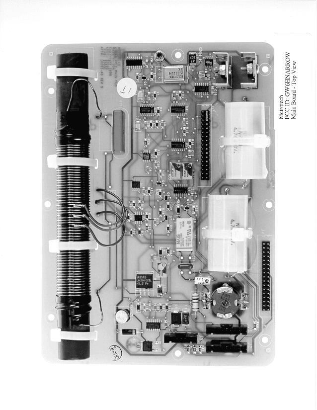
Click to zoom
Application Details
- Equipment Class
- DCD - Part 15 Low Power Transmitter Below 1705 kHz
- Date of Grant
- Apr 04, 1999
- Application Purpose
- Original Equipment
- Date of Application
- Mar 02, 1999
- Equipment Note
- Utility Safety Tool
- Frequency Range
- 0.03500000 - 0.03500000
- Company
- Metrotech Inc
- Country
- United States
Documents & Files
Document Text
Text extracted from the exhibit documents filed with the FCC. Open a document above to read the original.
Cover Letter(s)
File: R30457 February 22, 1999 Chief, Equipment Authorization Branch, Authorization and Evaluation Division, Office of Engineering and Technology FEDERAL COMMUNICATIONS COMMISSION P.O. Box 358315 Pittsburgh, PA 15251-5315 Gentlemen: The enclosed documents constitute a formal submittal and application for a Grant of Equipment Authorization pursuant to Subpart C of Part 15 of FCC Rules (CFR 47) regarding intentional radiators. Data within this report demonstrates that the equipment tested complies with the FCC limits for intentional radiators. This submittal was prepared by Elliott Laboratories, as duly authorized agent. A copy of the letter of our appointment as agent is enclosed. Please also find enclosed a check in the amount of $1075.00 for the application fee. If there are any questions or if further information is needed, please contact Elliott Laboratories for assistance. Sincerely, David W. Bare Principal Engineer DWB/bab Enclosures:Application Fee FCC Form 159 FCC Form 731 Agent Authorization Letter Emissions Test Report with Exhibits
Test Report
File: R30457 Page 1 of 10 Electromagnetic Emissions Test Report and Application for Grant of Equipment Authorization pursuant to FCC Part 15, Subpart C Specifications for an Intentional Radiator on the Metrotech Corp. Model: Arrow FCC ID:GW6HNARROW GRANTEE:Metrotech Corp. 488 Tasman Drive Sunnyvale, CA 94089 TEST SITE:Elliott Laboratories, Inc. 684 W. Maude Avenue Sunnyvale, CA 94086 REPORT DATE:February 22, 1999 FINAL TEST DATE:February 1, 1999 AUTHORIZED SIGNATORY:______________________________ David W. Bare Principal Engineer This report shall not be reproduced, except in its entirety, without the written approval of Elliott Laboratories, Inc. Elliott Laboratories, Inc. -- EMC DepartmentTest Report Report Date: February 22, 1999 File: R30457Page 2 of 10 pages TABLE OF CONTENTS COVER PAGE....................................................................................... 1 TABLE OF CONTENTS............................................................................ 2 SCOPE................................................................................................ 3 OBJECTIVE.......................................................................................... 3 STATEMENT OF COMPLIANCE................................................................ 3 EMISSION TEST RESULTS...................................................................... 4 LIMITS OF CONDUCTED INTERFERENCE VOLTAGE........................... 4 MEASUREMENT UNCERTAINTIES.................................................. 5 COMPLIANCE EXPLANATION........................................................ 5 EQUIPMENT UNDER TEST (EUT) DETAILS................................................. 6 GENERAL................................................................................... 6 INPUT POWER............................................................................. 6 PRINTED WIRING BOARDS............................................................ 6 ENCLOSURE............................................................................... 6 TEST SITE............................................................................................ 7 GENERAL INFORMATION.............................................................. 7 CONDUCTED EMISSIONS CONSIDERATIONS.................................... 7 MEASUREMENT INSTRUMENTATION...................................................... 7 INSTRUMENT CONTROL COMPUTER.............................................. 7 FILTERS/ATTENUATORS............................................................... 8 INSTRUMENT CALIBRATION......................................................... 8 TEST PROCEDURES............................................................................... 8 EUT AND CABLE PLACEMENT....................................................... 8 CONDUCTED EMISSIONS FROM ANTENNA PORT.............................. 8 SPECIFICATION LIMITS AND SAMPLE CALCULATIONS............................... 9 CONDUCTED EMISSIONS SPECIFICATION LIMITS, SECTION 15.207..... 9 POWER SPECIFICATION LIMITS, SECTION 15.213.............................. 9 SAMPLE CALCULATIONS - CONDUCTED EMISSIONS........................ 10 EXHIBIT 1:Test Equipment Calibration Data................................................. 1 EXHIBIT 2:Test Data Log Sheets............................................................... 2 EXHIBIT 5:Proposed FCC ID Label & Label Location...................................... 3 EXHIBIT 6:Detailed Photographs of Metrotech Model Arrow Construction.............. 4 EXHIBIT 7:Operator's Manual for Metrotech Model Arrow................................ 5 EXHIBIT 8:Block Diagram of Metrotech Model Arrow..................................... 6 EXHIBIT 9:Schematic Diagrams for Metrotech Model Arrow.............................. 7 EXHIBIT 10: Theory of Operation for Metrotech Model Arrow.............................. 8 Elliott Laboratories, Inc. -- EMC DepartmentTest Report Report Date: February 22, 1999 File: R30457Page 3 of 10 pages SCOPE An electromagnetic emissions test has been performed on the Metrotech transmitter model Arrow pursuant to Subpart C of Part 15 of FCC Rules for intentional radiators. Conducted and radiated emissions data has been collected, reduced, and analyzed within this report in accordance with measurement guidelines set forth in ANSI C63.4-1992 as outlined in Elliott Laboratories test procedures. The intentional radiator above has been tested in a simulated typical installation to demonstrate compliance with the relevant FCC performance and procedural standards. Final system data was gathered in a mode that tended to maximize emissions by varying orientation of EUT, orientation of power and I/O cabling, antenna search height, and antenna polarization. Every practical effort was made to perform an impartial test using appropriate test equipment of known calibration. All pertinent factors have been applied to reach the determination of compliance. The test results recorded herein are based on a single type test of the Metrotech model Arrow and therefore apply only to the tested sample. The sample was selected and prepared by Howard Ngo of Metrotech Corp.. OBJECTIVE The primary objective of the manufacturer is compliance with Subpart C of Part 15 of FCC Rules for the radiated and conducted emissions of intentional radiators. Certification of these devices is required as a prerequisite to marketing as defined in Part 2 the FCC Rules. Certification is a procedure where the manufacturer or a contracted laboratory makes measurements and submits the test data and technical information to the FCC. The FCC issues a grant of equipment authorization upon successful completion of their review of the submitted documents. Once the equipment authorization has been obtained, the label indicating compliance must be attached to all identical units which are subsequently manufactured. STATEMENT OF COMPLIANCE The tested sample of Metrotech model Arrow complied with the requirements o…
Text truncated - open the document above for the full version.
Test Report
Emissions Tes Client: Metrotech Corp.Date:2/1/99Test Eng Mehran M Birgani Product: Arrow TransmiterFile:T30112Proj. EngDavid Bare ObjectiveFinal QualificationSite:SVOATS #1Contact: Howard Ngo Spec:FCC Distance : -Approved: Ambient Conditions Temperature:12 °C Humidity:63 % RH Run #1: Conducted Emissions, 9 kHz -30 MHz, Sorted by Margin. FrequencyMeas.CorrectedFCCFCCDetector Azimuth Height Comments LevelLimitMarginPk/QP/Avgdegrees meters MHzdBμVdBmdBmdB 0.035114.2 32.240.0-7.8Pk - -Used 50dB Pad 0.10684.92.930.0-27.1Pk - -Used 50dB Pad 0.17777.2-4.830.0-34.8Pk - -Used 20dB Pad 0.24870.4 -11.630.0-41.6Pk - -Used 20dB Pad 0.07168.8 -13.230.0-43.2Pk - -Used 50dB Pad 0.31965.8 -16.230.0-46.2Pk - -Used 20dB Pad 0.39062.3 -19.730.0-49.7Pk - -Used 20dB Pad 0.46059.2 -22.830.0-52.8Pk - -Used 20dB Pad 0.21357.6 -24.430.0-54.4Pk - -Used 20dB Pad 0.53156.1 -25.930.0-55.9Pk - -Used 20dB Pad 0.60153.8 -28.230.0-58.2Pk - -Used 20dB Pad 0.63750.0 -32.030.0-62.0Pk - -Used 20dB Pad 0.70848.9 -33.130.0-63.1Pk - -Used 20dB Pad 0.85047.6 -34.430.0-64.4Pk - -Used 20dB Pad 0.92046.5 -35.530.0-65.5Pk - -Used 20dB Pad 0.99145.6 -36.430.0-66.4Pk - -Used 20dB Pad 1.13244.0 -38.030.0-68.0Pk - -Used 20dB Pad 2.89936.3 -45.730.0-75.7Pk - -Used 20dB Pad 2.68736.2 -45.830.0-75.8Pk - -Used 20dB Pad 25.52633.7 -48.330.0-78.3Pk - -Used 10dB Pad 25.24233.5 -48.530.0-78.5Pk - -Used 10dB Pad 25.02932.5 -49.530.0-79.5Pk - -Used 10dB Pad 14.21231.6 -50.430.0-80.4Pk - -Used 10dB Pad 24.11028.9 -53.130.0-83.1Pk - -Used 10dB Pad Note 1: Page 1
Contact Information
Applicant
Jim Waite
Technical Contact
Elliott LaboratoriesDavid W Bare
[email protected]408 245-7800
684 W. Maude · Sunnyvale, California · United States
Non-Technical Contact
Elliott LaboratoriesDavid W Bare
[email protected]408 245 7800
Technical Specifications
| # | Rule Parts | Frequency Range | Power Output | Tolerance |
|---|---|---|---|---|
| 1 | 15.213 | 0.035 MHz - 0.035 MHz | - | ppm |
Other Applications from Metrotech Inc
GW6RT9800
Jan 16, 1995Cable Locator
Equipment Class
DCD - Part 15 Low Power Transmitter Below 1705 kHz