H4IDG24RF002USB Dongle
Lite-on Technology Corp.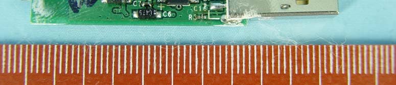
Click to zoom
Application Details
- Equipment Class
- DTS - Digital Transmission System
- Date of Grant
- Dec 18, 2004
- Application Purpose
- Original Equipment
- Date of Application
- Dec 18, 2004
- Equipment Note
- USB Dongle
- Frequency Range
- 2402.00000000 - 2479.00000000
- Company
- Lite-on Technology Corp.
- Country
- Taiwan
Documents & Files
Document Text
Text extracted from the exhibit documents filed with the FCC. Open a document above to read the original.
Users Manual
Silitek Coorperation Confidential SM-2065 第 1 頁,共9 頁 User’s Manual Model: R-RB5;C-UR37 Customer: Logitech Version : 0.1 Issue Date : SEP.06. 2004 Prepared By: Muchuan Lee Silitek Coorperation Confidential SM-2065 第 2 頁,共9 頁 Table of Contents 1 General.......................................................................................................................... 3 2 Product Outline ......................................................................................................... 3 3.Electrical Specification................................................................................................... 3 4.Functions and Features................................................................................................. 8 4.1 Wireless Connection and Radio feature .............................................................. 8 4.2 Functionality of Presentation ............................................................................... 9 4.2.1 HID Function .................................................................................................... 9 4.2.2 LCD Display ................................................................................................... 10 4.2.3 Laser Point ..................................................................................................... 11 Silitek Coorperation Confidential SM-2065 第 3 頁,共9 頁 1.General R-RB5;C-UR37 is a product of 2.4GHZ radio presenter,it’s a special designed for Logitech,which the whole package including a wireless presenter and an USB nano-Dongle which as bridage with PC system,it offers the function as a human input device especially it be used for making a presentation . WirelessUSB 2.4GHZ radio solution of Cyptess are employed, it has the best in the radio performance supporting two way and muti-channels communication in wireless interface via 2.4GHZ DSSS.It’s designed for portable use such as a palm size of wirelss presenter, a thrumble size of nanodongle ,presenter inside also reserve a space to storge the nano-dongle while not use .A low power consumption designed was also implemented to the presenter ,so it is only required two AAA batteries installed inside for use.(refer to user’s manual). Besides providing the major function in PowerPoint control,the product also offer many extra function in friendly use like displaying a timer of presentation, vibration alert ,laser point and low battery indication. The USB Nano-dongle of the product meets the USB version 1.1 specification . 2 Product Outline *Product Outline: 3 Electrical Specification 3.1 Power Consumption Silitek Coorperation Confidential SM-2065 第 4 頁,共9 頁 Operation Voltage: Voltage supplied to presenter : 3 VDC (AAA battery *2) Voltage supplied to Dongle : 5 VDC Operation Current: USB Dongle : Under 5 VDC power supplied ,typical current is 18mA. PC System Suspend current : 1mA Maximum current of Pairing : 80 mA Laser Point : 25~45 mA, Output power of beam : under 1mW Power consumption: Typical power consumption of Presenter will be less than 40mW. Typical power consumption of Dongle will be less than 100mW. 3.2 Circuitry Design 1. Presenter :Radio transceiver-- Cypress LS RADIO TRANSCEIVER CYWUSB6934,QFN-48 pin Functionality IC -- CY8C27443 PROGRAMMABLE ,28 pin SSOP . 2. USB Dongle: Radio transceiver-- Cypress LS RADIO TRANSCEIVER CYWUSB6934,QFN-48 pin Functionality IC -- Cypress USB controller , CY8C27643 QSOP. 3.3 USB connector of Dongle USB 1.1 connector consists of four conductors, one power conductor, one GND conductor and two signal conductors and an overall shield. USB 1.1 connector is the Low-speed connector which is a Series ‘A’ plug Silitek Coorperation Confidential SM-2065 第 5 頁,共9 頁 4. Functionality and Radio Feature *Functional Block diagram : : Main Feature. * Intelligent Auto- channel switching function to have a best radio connection always. * Two way radio communication . * Maximum 64k transmission baud rate . * Low power consumption design/Low battery indicated function. 4.1 Wireless Connection and Radio feature ---- Bind function (like Bluetooth paring ) and Connection *Bind mode function: The bind function is like the pairing function of bluetooth that allow many same radio products to be used at same time and same place also avoid the interference between same product each other. We shall complete the bind function before the wireless device to be first used. (End user needn’t do that due to It had done at manufacturer site ). *Procedure of performing Bind function (by following step by step) : Plugging the nano-dongle attached to PC then turn on PC system, or attached the device by hot Radio Link: two way communication Vibrator Functionality& Base-Band 2.4 GHZ Radio module LCD display Laser point 2.4 GHZ Radio module Base-Band & USB controller PC Host Presenter Emitter Dongle Receiver Silitek Coorperation Confidential SM-2065 第 6 頁,共9 頁 plugging. b. Run the bind AP on PC, it shall be under the WIN2000 or above, the screen will shown up the “bind window” as following shown .in which will appear the “initial value” of the numbers of wireless and sub channel. It means USB enumerated successfully and being ready for bind c. Activate the bind button on the “bind window” above. At same time, press the bind button on the back of presenter (Assume the batteries was installed). The numbers of “wireless” and “Sub Channel” will be a various for scaning that is in binding. d. It is completed the binding when the numbers scaning are fast to settle at some value. Suppose the numbers scaning return to be “initial value” or over 10 sec,maybe it fail to bind and we have to re-bind again. *Auto-Connection: The radio connection (wireless function on line) will be done automatically between presenter and nano-dongle when we turn ON the product both presenter and dongle also enable the HID function (Stoke any Key of presentation function). 4.2 Functionality of presentation 4.2.1 HID function There are overall 9 buttons o…
Text truncated - open the document above for the full version.
Cover Letter(s)
American Telecommunications Certification Body Inc. 6731 Whittier Ave, McLean, VA 22101 December 6, 2004 RE: FCC ID: H4IDG24RF002_ATCB001981 Attention: Ellis Wu I have a few comments on this Application. Please note that further comments may arise in response to answers provided to the questions below. 1. Please note that the 731 says the operating frequency of the device is 2412 to 2462MHz, yet the block diagram and other documentation states it is 2402 to 2479MHz. Please be consistent in your documentation and please correct all documents to show the same frequency range of the device. 2. What is this device? The operational description says it is a frequency hopping device, however the report presents this as more of a Digital Transmission System. Please provide the appropriate equipment code of the device on the 731 form. 3. Please provide a Block diagram that is in accordance with 2.1033(b)(5). Please have the block diagram explain what this device is. 4. FYI – as this is a computer peripheral you need to show the DoC label on the device as required by part 15.19(b)(1). 5. In conjunction with item 2 and 3, what is this device? Please note that while the operational description calls this a FHSS device, this is not a Bluetooth device and it appears to be more of a DTS device using 78 channels. Please provide an operational description of the device detailing how it operates. What makes it a FHSS system? If it is not an FHSS, then please provide evidence of just what kind of device it is to support your testing. 6. If this is a frequency hopping device as stated in the operational description, please provide the pseudo random frequency list and describe how the hopping is pseudo-random. 7. Please note if this is a FHSS device, please provide the required channel separation data plots and the dwell time plots. If this is not a FHSS device please fully explain what this device is and how it operates so a determination of the required tests can be made and evaluated. 8. Please note that the manual does not contain any of the required FCC statements. Please provide a manual that has all of the required FCC statements. This includes the statements of 15.19(a)(3) and 15.21. 9. It is not clear from the radiated emissions test setup photo if the EUT is plugged into the USB port of the Laptop or not. Please clearly identify the location of the EUT and please clearly show the EUT in the radiated emissions test setup photos. 10. Please provide evidence that the receiver meets the receiver requirements of 15.247(a)(1). 11. Please note that the operational description states the device has 79 operating frequencies but the report states it has 78 frequencies. Please be consistent in your documentation and please correct all documents to show the proper number of operating frequencies used in the device. 12. FYI – please note that the FCC has stated that if you are going to use a peak or QP reading to show compliance of a device to the average conducted limits then you MUST compare the peak or QP to the average limit. For example, this means that on page 13 of the report the 209kHz reading does not have 14.85dB margin but only 4.85dB margin; and 1.297MHz does not have 11.dB margin but on ly 1.36dB margin. If you are going to use peak or QP readings to show compliance, then please compare your reading to the proper limits as specified by the FCC. This error occurs on page 14 through 18 as well where some readings only show less than 1dB margin. 13. Please note that on page 20 of the report you state that the minimum 20dB bandwidth is 500kHz. Please also note that your operational description calls this device a Frequency Hopping device. While devices operating in the 902MHz range have a maximum 500kHz 20dB bandwidth limit and while devices operating in the 5GHz range have a maximum 1MHz 20dB bandwidth limit, 2.4GHz range FHSS devices do not have this minimum 20dB bandwidth specification. Please note that from the data and information provided, it is not possible to determine what this device is. It appears to be more of a DSSS than FHSS device. Please explain the operation of this device and apply proper limits. z Page 2 December 6, 2004 14. Dennis Ward mailto:[email protected] The items indicated above must be submitted before processing can continue on the above referenced application. Failure to provide the requested information may result in application termination. Correspondence should be considered part of the permanent submission and may be viewed from the Internet after a Grant of Equipment Authorization is issued. Please do not respond to this correspondence using the email reply button. In order for your response to be processed expeditiously, you must submit your documents through the AmericanTCB.com website. Also, please note that partial responses increase processing time and should not be submitted. Any questions about the content of this correspondence should be directed to the sender.
Cover Letter(s)
1 dward ATCB From: dward ATCB [[email protected]] Sent: Sunday, December 12, 2004 12:50 AM To: '[email protected]' Cc: '[email protected]'; 'William Graff' Subject: RE: Solve the comment for H4IDG24RF002_ATCB001981 HI Wendy Please note that you have not sufficiently addressed the following items in the comments. 1 Item 2 of the comments has not been properly addressed in the operational description. The operational description is to provide information as to what the device is. Your description only states it has 78 frequencies but has not provided any information on what the device is. Is it a FHSS system or is it a DTS system? Is the 'digital modulation' spoken of in the email a digitally generated pseudo random frequency or is does this mean the device is a Digital Transmission System? What is it? Please give an operational description that more suitably describes the device. If it is a DTS, please clearly state this in the 731 and operational description. lPease provide this equipment code. 2 You have not properly addressed item 3 of the comments - again, what is the device. The block diagram make is look like only a receiver. If the 'emitter' shown in the upper part is the rf transmitter, then you must provide a block diagram of that transmitter that is in accordance with 2.1033. Please review 2.1033 and provide a block diagram that meets its requirements. 3 You still have not provided a label that shows the DoC info. 4 Item 5 of the comments has not been addressed - see item 2 of the comments - what is the device? 5 You have not addressed item 9. I need to be able to see the EUT in the setup photos. Please provide a setup photos that clearly shows the EUT. I think that these are the only remaining questions, but I cannot proceed until they are properly answered. Again, a proper explanation of this device is needed. Please note that as this is not a WLAN type device, which can be handled under a very generic operational description, this device must have a reasonable operational description provided to determine exactly what it is. Thanks Dennis Ward ATCB Phone - Headquarters (703) 847-47002 Phone - Dt Associates (209) 966-2145 Phone -Alternate business (703) 880-4841 -----Original Message----- From: [email protected] [mailto:[email protected]] Sent: Thursday, December 09, 2004 10:44 PM To: [email protected] Cc: [email protected] Subject: 回信: Solve the comment for H4IDG24RF002_ATCB001981 Dear Dennis The 731 form, operational description, block and manual had been uploaded to ATCB website. The EUT uses the Digital modulation and plugs into the USB port. so we do not modify the test setup photo. Please check, and would you please send the grant today? Thanks for your assistance! 2 Best Regards Wendy Liao Wendy Liao (廖意紋)/ ADT Corp. TEL: 03-318-3232 EXT 1625 FAX: 03-318-5050 Email: [email protected] 地址:桃園縣龜山鄉文化村華亞二路19號 "dward ATCB" <[email protected]> 收件人 2004/12/06 下午 <[email protected]>, 05:58 <[email protected]>, <[email protected]> 副本抄送 請回信 給 <[email protected]> 主旨 H4IDG24RF002_ATCB001981 Please see comments Thanks Dennis Ward ATCB Phone - Headquarters (703) 847-4700 Phone - Dt Associates (209) 966-2145 Phone -Alternate business (703) 880-4841 (See attached file: 12-05-04 H4IDG24RF002_ATCB Comments.pdf)
External Photos
Page 1 CONSTRUCTION PHOTOS OF EUT
ID Label/Location Info
FCC ID: H4IPR24RF001 Model Name : MADE IN CHINA RATING:3V 150mA R-RB5 IC:4491A-CAPR2401 gepruflegeprufle SicherheltSicherhelt Rheinland gepruflegeprufle SicherheltSicherhelt RheinlandRheinland ATTENTION LASER RADIATION DO NOT STARE INTO BEAM LASER DIODE Wavelength 640-660 nm Maximum Output<1mW CLASS 2 LASER PRODUCT IEC 60825-1:2001 P/N : PID : Model Name : C-UR37Model Name : C-UR37 MADE IN CHINAMADE IN CHINA RATING:5V , 90mARATING:5V , 90mA FCC ID: H4IDG24RF002 R 1 28.5 9.5 gepruflegeprufle SicherheltSicherhelt RheinlandRheinland P/N : PID : Tested To ComplyTested To Comply With FCC StandardsWith FCC Standards FOR HOME OR OFFICE U SEFOR HOME OR OFFICE U SE 30.5 19.34 R1.75
Internal Photos
Page 2 Page 3
Operational Description
FCC ID: H4IDG24RF002 Report No.: RF931116A05A Operational Description This device is a Dongle which operates in the 2.4GHz frequency spectrum This device is a DTS device with 78 frequencies. The Cypress 2.4 GHZ WirelessUSB solution (Cypress’s proprietary protocol ) employed. There is SPI interface between radio module and base band Micom (USB). The device communicates with PC via USB 1.1 interface. The antenna type is printed antenna and there is no antenna connector used. The other instruction, please have a look at the users manual.
Test Report
FCC ID: H4IDG24RF002 Report No.: RF931116A05A1Issued: Nov. 26, 2004 FCC TEST REPORT REPORT NO. : RF931116A05A MODEL NO. : C-UR37 RECEIVED : Nov. 16, 2004 TESTED : Nov. 22 ~ Nov. 24, 2004 APPLICANT : Lite-On Technology Corporation ADDRESS : 5F, 16, Sec 4, Nanking E. Road, Taipei, Taiwan, R.O.C. ISSUED BY : Advance Data Technology Corporation LAB ADDRESS : No. 47, 14th Ling, Chia Pau Tsuen, Lin Kou Hsiang 244, Taipei Hsien, Taiwan, R.O.C. TEST LOCATION : No. 19, Hwa Ya 2nd Rd., Wen Hwa Tsuen, Kwei Shan Hsiang, Taoyuan Hsien 333, Taiwan, R.O.C. This test report consists of 52 pages in total. It may be duplicated completely for legal use with the approval of the applicant. It should not be reproduced except in full, without the written approval of our laboratory. The client should not use it to claim product endorsement by CNLA, A2LA or any government agencies. The test results in the report only apply to the tested sample. 0528 ILAC MR A No. 2177-01 FCC ID: H4IDG24RF002 Report No.: RF931116A05A2Issued: Nov. 26, 2004 Table of Contents 1CERTIFICATION ...................................................................................................4 2SUMMARY OF TEST RESULTS ...........................................................................5 2.1MEASUREMENT UNCERTAINTY.........................................................................5 3GENERAL INFORMATION....................................................................................6 3.1GENERAL DESCRIPTION OF EUT ......................................................................6 3.2DESCRIPTION OF TEST MODES ........................................................................7 3.3GENERAL DESCRIPTION OF APPLIED STANDARDS .......................................8 3.4DESCRIPTION OF SUPPORT UNITS ..................................................................9 3.5CONFIGURATION OF SYSTEM UNDER TEST...................................................9 4TEST TYPES AND RESULTS .............................................................................10 4.1CONDUCTED EMISSION MEASUREMENT ......................................................10 4.1.1LIMITS OF CONDUCTED EMISSION MEASUREMENT....................................10 4.1.2TEST INSTRUMENTS.........................................................................................10 4.1.3TEST PROCEDURES ......................................................................................... 11 4.1.4DEVIATION FROM TEST STANDARD ............................................................... 11 4.1.5TEST SETUP.......................................................................................................12 4.1.6EUT OPERATING CONDITIONS ........................................................................12 4.1.7TEST RESULTS ..................................................................................................13 4.2RADIATED EMISSION MEASUREMENT ...........................................................19 4.2.1LIMITS OF RADIATED EMISSION MEASUREMENT.........................................19 4.2.2TEST INSTRUMENTS.........................................................................................20 4.2.3TEST PROCEDURES .........................................................................................21 4.2.4DEVIATION FROM TEST STANDARD ...............................................................21 4.2.5TEST SETUP.......................................................................................................22 4.2.6EUT OPERATING CONDITIONS ........................................................................22 4.2.7TEST RESULTS ..................................................................................................23 4.36dB BANDWIDTH MEASUREMENT...................................................................28 4.3.1LIMITS OF 6dB BANDWIDTH MEASUREMENT ................................................28 4.3.2TEST INSTRUMENTS.........................................................................................28 4.3.3TEST PROCEDURE............................................................................................29 4.3.4DEVIATION FROM TEST STANDARD ...............................................................29 FCC ID: H4IDG24RF002 Report No.: RF931116A05A3Issued: Nov. 26, 2004 4.3.5TEST SETUP.......................................................................................................29 4.3.6EUT OPERATING CONDITIONS ........................................................................29 4.3.7TEST RESULTS ..................................................................................................30 4.4MAXIMUM PEAK OUTPUT POWER ..................................................................34 4.4.1LIMITS OF MAXIMUM PEAK OUTPUT POWER MEASUREMENT ...................34 4.4.2TEST INSTRUMENTS.........................................................................................34 4.4.3TEST PROCEDURES .........................................................................................34 4.4.4DEVIATION FROM TEST STANDARD ...............................................................35 4.4.5TEST SETUP.......................................................................................................35 4.4.6EUT OPERATING CONDITIONS ........................................................................35 4.4.7TEST RESULTS ..................................................................................................36 4.5POWER SPECTRAL DENSITY MEASUREMENT..............................................37 4.5.1LIMITS OF POWER SPECTRAL DENSITY MEASUREMENT ...........................37 4.5.2TEST INSTRUMENTS.........................................................................................37 4.5.3TEST PROCEDURE............................................................................................37 4.5.4DEVIATION FROM TEST STANDARD .........................................…
Text truncated - open the document above for the full version.
Test Setup Photos
CONDUCTED EMISSION TEST EUT RADIATED EMISSION TEST EUT
Contact Information
Applicant
Chris Chuang(Engineer)
Technical Contact
Advance Data Technology CorporationEllis Wu
[email protected]886-3-318-3232
13-1, Lane19, WenShan 3rd ., St., · Taoyuan · Taiwan
Test Firm
Bureau Veritas CPS (H.K.) Ltd. Taoyuan BranchRichard Chen
Technical Specifications
| # | Rule Parts | Frequency Range | Power Output |
|---|---|---|---|
| 1 | 15C | 2.40 GHz - 2.48 GHz | 1.00 mW |
Other Applications from Lite-on Technology Corp.
H4ISK2186
Dec 23, 2025Wireless Keyboard
Equipment Class
DXX - Part 15 Low Power Communication Device TransmitterH4ISM2186
Nov 19, 2025Wireless Mouse
Equipment Class
DXX - Part 15 Low Power Communication Device TransmitterH4IKB555
Mar 27, 2024Wireless Keyboard
Equipment Class
DTS - Digital Transmission System
H4IWM118
Aug 25, 2021Wireless Mouse
Equipment Class
DTS - Digital Transmission System
H4IUD2203
Aug 24, 2021Dongle
Equipment Class
DTS - Digital Transmission System