H4IKB24RF001WIRELESS USB KEYBOARD
Lite-on Technology Corp.Application Details
- Equipment Class
- DTS - Digital Transmission System
- Date of Grant
- Nov 21, 2004
- Application Purpose
- Original Equipment
- Date of Application
- Nov 21, 2004
- Equipment Note
- WIRELESS USB KEYBOARD
- Frequency Range
- 2402.00000000 - 2479.00000000
- Company
- Lite-on Technology Corp.
- Country
- Taiwan
Documents & Files
Document Text
Text extracted from the exhibit documents filed with the FCC. Open a document above to read the original.
Users Manual
The class B digital appartaus meets all requirement of Canadian Interference-Causing Equipment Regulation. What you will need: KeyboardDongle Palm Rest AA Batteries Insert batteries into Mouse and Keyboard. Do not press the yellow connect buttons. Mouse optical sensor will light if batteries are placed properly. Mouse Connect Dongle to any USB port on the computer. Optional: Attach Keyboard palm rest. Setting up your IBM Wireless USB Keyboard & Mouse AAA Batteries Turn on your computer to begin use. If you purchased your IBM Wireless Keyboard & Mouse with a IBM computer system, Setup is complete! If you purchased your Wireless Desktop separately, insert the software application CD in CD-ROM drive and double click the Setup.exe file to install. Installation is complete within 10 seconds. Hot Key ( Customized) Connect button: used for manual connect in step c below. LED is on when bind success within ten seconds. LED is on when data in & send to host. Check USB connection.Make sure batteries are inserted proprly Turn on computer. Establish connection manually. 1.First press and release the2.First press and release the yellow connect button on the yellow connect button on the mouse and then the dongle. keyboard and then the dongle. Keyboard and Mouse not Responding? Getting to know the Keyboard and Dongle. Federal Communication Commission Interference Statement This equipment has been tested and found to comply with the limits for a Class B digital device, pursuant to Part 15 of the FCC Rules. These limits are designed to provide reasonable protection against harmful interference in a residential installation. This equipment generates, uses and can radiate radio frequency energy and, if not installed and used in accordance with the instructions, may cause harmful interference to radio communications. However, there is no guarantee that interference will not occur in a particular installation. If this equipment does cause harmful interference to radio or television reception, which can be determined by turning the equipment off and on, the user is encouraged to try to correct the interference by one of the following measures: - Reorient or relocate the receiving antenna. - Increase the separation between the equipment and receiver. - Connect the equipment into an outlet on a circuit different from that to which the receiver is connected. - Consult the dealer or an experienced radio/TV technician for help. This device complies with Part 15 of the FCC Rules. Operation is subject to the following two conditions: (1) This device may not cause harmful interference, and (2) this device must accept any interference received, including interference that may cause undesired operation. FCC Caution: Any changes or modifications not expressly approved by the party responsible for compliance could void the user's authority to operate this equipment. IMPORTANT NOTE: FCC Radiation Exposure Statement: This equipment complies with FCC radiation exposure limits set forth for an uncontrolled environment. End users must follow the specific operating instructions for satisfying RF exposure compliance. This transmitter must not be co-located or operating in conjunction with any other antenna or transmitter.
External Photos
Page 1 CONSTRUCTION PHOTOS OF EUT
ID Label/Location Info
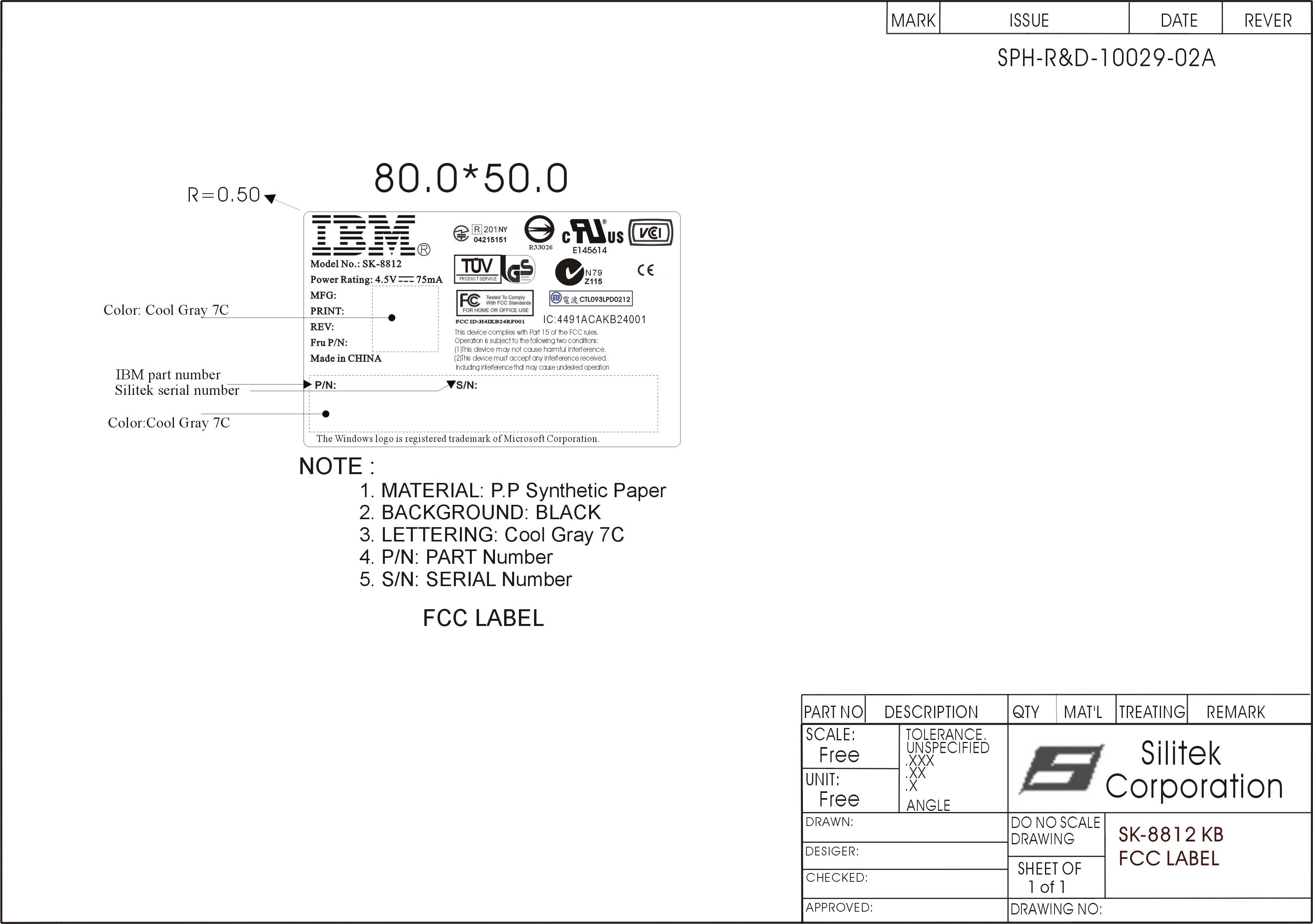
(Fig. 1) FCC ID: H4IKB24RF001 FCC LABEL LOCATION The label will be permanently affixed at a conspicuous location on the device. Label
Internal Photos
Page 1 CONSTRUCTION PHOTOS OF EUT Page 2 Page 3
Operational Description
FCC ID: H4IKB24RF001 Report No.: RF930921A11 Operational Description The transmitter of the EUT (Wireless USB Keyboard) is powered by 4.5V Batteries. The type of antenna is printed antenna. The output power of this device is very low. Under normal use condition, the transmitter and the receiver are quite close, so high EIRP power is neither necessary nor allowed because of interference.
Test Report
FCC ID: H4IKB24RF001 Report No.: RF930921A111Report Format Version 2.0.0 FCC TEST REPORT REPORT NO.: RF930921A11 MODEL NO.: SK-8812 RECEIVED: Sep. 22, 2004 TESTED: Sep. 23 ~ Oct. 28, 2004 ISSUED: Nov. 4, 2004 APPLICANT: Lite-On Technology Corporation ADDRESS: 90,Chien I Road, Chung Ho, Taipei Hsien, Taiwan, R.O.C. ISSUED BY: Advance Data Technology Corporation LAB ADDRESS: No. 47, 14th Ling, Chia Pau Tsuen, Lin Kou Hsiang 244, Taipei Hsien, Taiwan, R.O.C. TEST LOCATION: No. 47, 14th Ling, Chia Pau Tsuen, Lin Kou Hsiang 244, Taipei Hsien, Taiwan, R.O.C. This test report consists of 42 pages in total. It may be duplicated completely for legal use with the approval of the applicant. It should not be reproduced except in full, without the written approval of our laboratory. The client should not use it to claim product endorsement by CNLA, A2LA or any government agencies. The test results in the report only apply to the tested sample. 0528 ILAC MRA No. 2177-01 FCC ID: H4IKB24RF001 Report No.: RF930921A112Report Format Version 2.0.0 Table of Contents 1CERTIFICATION..............................................................................................4 2SUMMARY OF TEST RESULTS .....................................................................5 2.1MEASUREMENT UNCERTAINTY...................................................................5 3GENERAL INFORMATION ..............................................................................6 3.1GENERAL DESCRIPTION OF EUT ................................................................6 3.2DESCRIPTION OF TEST MODES ..................................................................7 3.3GENERAL DESCRIPTION OF APPLIED STANDARDS .................................8 3.4DESCRIPTION OF SUPPORT UNITS ............................................................9 3.5CONFIGURATION OF SYSTEM UNDER TEST.............................................9 4TEST TYPES AND RESULTS .......................................................................10 4.1CONDUCTED EMISSION MEASUREMENT.................................................10 4.2RADIATED EMISSION MEASUREMENT .....................................................10 4.2.1 LIMITS OF RADIATED EMISSION MEASUREMENT ...................................10 4.2.2 TEST INSTRUMENTS ................................................................................... 11 4.2.3 TEST PROCEDURES ...................................................................................12 4.2.4 DEVIATION FROM TEST STANDARD ..........................................................12 4.2.5 TEST SETUP.................................................................................................13 4.2.6 EUT OPERATING CONDITIONS ..................................................................13 4.2.7 TEST RESULTS ............................................................................................14 4.36dB BANDWIDTH MEASUREMENT .............................................................19 4.3.1 LIMITS OF 6DB BANDWIDTH MEASUREMENT ..........................................19 4.3.2 TEST INSTRUMENTS ...................................................................................19 4.3.3 TEST PROCEDURE ......................................................................................20 4.3.4 DEVIATION FROM TEST STANDARD ..........................................................20 4.3.5 TEST SETUP.................................................................................................20 4.3.6 EUT OPERATING CONDITIONS ..................................................................20 4.3.7 TEST RESULTS ............................................................................................21 4.4MAXIMUM PEAK OUTPUT POWER.............................................................25 4.4.1 LIMITS OF MAXIMUM PEAK OUTPUT POWER MEASUREMENT..............25 4.4.2 TEST INSTRUMENTS ...................................................................................25 4.4.3 TEST PROCEDURES ...................................................................................26 4.4.4 DEVIATION FROM TEST STANDARD ..........................................................26 4.4.5 TEST SETUP.................................................................................................26 FCC ID: H4IKB24RF001 Report No.: RF930921A113Report Format Version 2.0.0 4.4.6 EUT OPERATING CONDITIONS ..................................................................26 4.4.7 TEST RESULTS ............................................................................................27 4.5POWER SPECTRAL DENSITY MEASUREMENT ........................................28 4.5.1 LIMITS OF POWER SPECTRAL DENSITY MEASUREMENT ......................28 4.5.2 TEST INSTRUMENTS ...................................................................................28 4.5.3 TEST PROCEDURE ......................................................................................29 4.5.4 DEVIATION FROM TEST STANDARD ..........................................................29 4.5.5 TEST SETUP.................................................................................................29 4.5.6 EUT OPERATING CONDITIONS ..................................................................29 4.5.7 TEST RESULTS ............................................................................................30 4.6BAND EDGES MEASUREMENT...................................................................34 4.6.1 LIMITS OF BAND EDGES MEASUREMENT ................................................34 4.6.2 TEST INSTRUMENTS ...................................................................................34 4.6.3 TEST PROCEDURE ......................................................................................34 4.6.4 DEVIATION FROM TEST STANDARD ..........................................................34 4.6.5 EUT OPERATING CONDITION ...................................................…
Text truncated - open the document above for the full version.
Test Setup Photos
FCC ID: H4IKB24RF001 Report No.: RF930921A1141Report Format Version 2.0.0 5 PHOTOGRAPHS OF THE TEST CONFIGURATION RADIATED EMISSION TEST
Contact Information
Applicant
Chris Chuang(Engineer)
Test Firm
Advance Data Tech. Corp. Hsin Chu EMCStephen Chen
Technical Specifications
| # | Rule Parts | Frequency Range | Power Output |
|---|---|---|---|
| 1 | 15C | 2.40 GHz - 2.48 GHz | 2.00 mW |
Other Applications from Lite-on Technology Corp.
H4ISK2186
Dec 23, 2025Wireless Keyboard
Equipment Class
DXX - Part 15 Low Power Communication Device TransmitterH4ISM2186
Nov 19, 2025Wireless Mouse
Equipment Class
DXX - Part 15 Low Power Communication Device TransmitterH4IKB555
Mar 27, 2024Wireless Keyboard
Equipment Class
DTS - Digital Transmission System
H4IWM118
Aug 25, 2021Wireless Mouse
Equipment Class
DTS - Digital Transmission System
H4IUD2203
Aug 24, 2021Dongle
Equipment Class
DTS - Digital Transmission System