H4IKB27RF001RF K/B
Lite-on Technology Corp.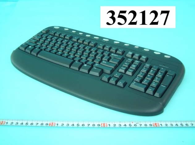
Click to zoom
Application Details
- Equipment Class
- DXX - Part 15 Low Power Communication Device Transmitter
- Date of Grant
- Sep 08, 2003
- Application Purpose
- Original Equipment
- Date of Application
- Sep 08, 2003
- Equipment Note
- RF K/B
- Frequency Range
- 27.14500000 - 27.14500000
- Company
- Lite-on Technology Corp.
- Country
- Taiwan
Documents & Files
Document Text
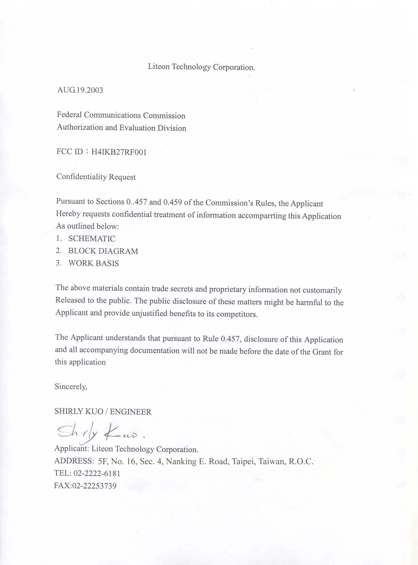
Text extracted from the exhibit documents filed with the FCC. Open a document above to read the original.
Users Manual
LITE-ON Technology Department: HIS R&D User’s Manual For Model : SK-7260 RF Wireless Keyboard Prepared :Muchuan Lee Version: 1.0 Department: HIS, R&D Date: May. 22th, 2003 LITE-ON Technology Department: HIS R&D Table of Contents 1. GENERAL MAIN FEATURE.............................................................................................................1 SOFTWARE REQUIREMENT.............................................................................................1 2. M ECHANICAL ID KEYBOARD/RECEIVER......................................................................................................2 3. E LECTRICAL FEATURE 3.1 K EYBOARD TRANSMITTER......................................................................................................3 3.1.1 Operating voltage ....................................................................................................................................................4 3.1.2 Current consumption................................................................................................................................................4 3.1.3 Power consumption..................................................................................................................................................4 3.1.4 Low Power Indicator................................................................................................................................................4 3.2 RECEIVER.................................................................................................................................5 3.2.1 Operating voltage ....................................................................................................................................................5 3.2.2 Current consumption................................................................................................................................................5 3.3 FUNCTION DESCRIPTION..........................................................................................................5 3.3.1 Interface specification with host PC ........................................................................................................................5 3.3.2. Channel and ID default setting................................................................................................................................6 4. NOTE SK-7260 RF WIRELESS KEYBOARD Page No: 1 of 6 1. General SK-7260 is a 27 MHZ RF keyboard set, the product is composed of a wireless desk top PC keyboard and a PS2 receiver. The keyboard includes Standard function keys and several (option) easy access keys. General the receiver supports both keyboard and mouse function. There are only described keyboard and receiver functionality in the product specification but excluded mouse specification. The product package includes wireless keyboard and receiver, mouse device is optional according to customer’s demend. 1.1 Main feature The product provides 2 channels /256 ID operation to prevent frequency interference. The receiver interface of supporting both keyboard and mouse to the system through PS2 ports. . z Single chip keyboard & Receiver controller. z Phantom key detection. z Low power consumption . z 4k bps baud rate in air. z Provides 2 RF channels . z 256 ID codes randomly generated to resist interference. z EEPROM interface for ID keeping z Low battery detector function for transmitter. 1.2 Software requirement The keyboard, receiver and drivers are compatible with operating systems that are WIN98, Windows Millennium and Windows 2000. The driver-application also must meet all current and future Microsoft WHQL requirements. SK-7260 RF WIRELESS KEYBOARD Page No: 2 of 6 2. Mechanical ID Keyboard: Receiver : SK-7260 RF WIRELESS KEYBOARD Page No: 3 of 6 3. Electrical Specification Functional Block diagram: Microprocessor MA6231 3.1 Keyboard Transmitter Operating voltage The operating voltage range for keyboard is 2 ~ 3.3 Vdc. There are 2 AA batteries providing 3.0V for operation f Current consumption Typical current consumption is 8 mA, .Maximum at 10 mA Suspend current is about 80 uA. Power consumption The power consumption is less than 0.024 W at operation mode and 240 uW at sleep mode. Low Power Indicator Low power indicator on the keyboard will be lit during hitting key when the battery voltage in the keyboard transmitter is less than about 2V. CPU Crystal : 32.768KHz RF Link PC Host PS2 Interface cable Low power indicator NumL ,CAP, Scrol LED Data indicator Keyboard (Base-Band) CPU Crystal : 32.768KHz TX-Freq : 27.145 MHz RX-Freq : Crystal : 26.690 /26.590 MHz Base-Band Microprocessor MA6135 SK-7260 RF WIRELESS KEYBOARD Page No: 4 of 6 3.1.1 Circuitry PCB Assembly Microprocessor MA6231 , MosArt ‘s Chip is applied. It’s placed on the PCB main board. There is also an antenna connected to this PCB for transmitting RF signal. 3.1.2 Battery Life The battery life under the operating condition of 10 keystrokes/sec continuous use is 80 hours for alkaline type and 30 hours for Zinc-Carbon type. 3.1.3 Effective Transmission Distance Effective transmission distance is 2 meters. 3.1.4 Features of keyboard This model contains easy access keys, including web. and multimedia keys . There is one LED on the keyboard for battery low power indication. .It has a standard keyboard function with the language layout of US English version. Two AA batteries are to be installed at the bottom of the keyboard for operation. There is a channel selection button at the bottom side of keyboard . Single chip solution , imbedded DC-to-DC converter to prevent malfunction of low battery power ,integrated RF components especially optimized for 27 MHz RF keyboard transmitter 32.768kHz main clock to reach a quite low power consumption. Easy Acess Key Code Table Win2000 compatible, they are include,refer to table below: PS/2 Hot key No . Usage Name / Key Name Set1 Make Set1 Break Set2 Make Set2 …
Text truncated - open the document above for the full version.
External Photos
FCC ID: H4IKB27RF001 Number1 FRONT SIDE OF EUT FCC ID: H4IKB27RF001 Number2 REAR SIDE OF EUT
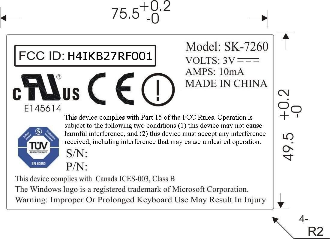
ID Label/Location Info
FCC ID: H4IKB27RF001 Label Location
Internal Photos
FCC ID: H4IKB27RF001 Number 1 MECHANICAL CONSTRUCTION FCC ID: H4IKB27RF001 Number 2 MECHANICAL CONSTRUCTION FCC ID: H4IKB27RF001 Number 3 MECHANICAL CONSTRUCTION FCC ID: H4IKB27RF001 Number 4 FRONT SIDE OF MAIN BOARD FCC ID: H4IKB27RF001 Number 5 REAR SIDE OF MAIN BOARD
Test Report
FCC TEST REPORT Report No. : F352127 SPORTON International Inc. TEL : 886-2-2696-2468 FAX : 886-2-2696-2255 FCC TEST REPORT for 47 CFR, Part 15, Subpart C Equipment : RF K/B Model No. : SK-7260 FCC ID : H4IKB27RF001 Filing Type : Certification Applicant : LITEON TECHNOLOGY CORPORATION 5F, No. 16, Sec. 4, Nanking E. Road Taipei, Taiwan, R.O.C. The test result refers exclusively to the test presented test model / sample. Without written approval of SPORTON International Inc., the test report shall not be reproduced except in full. Certificate or Test Report must not be used by the applicant to claim the product in this test report endorsement by NVLAP or any agency of U.S. government. SPORTON International Inc. 6F, No.106, Sec. 1, Hsin Tai Wu Rd., Hsi Chih, Taipei Hsien, Taiwan, R.O.C. FCC TEST REPORT Report No. : F352127 SPORTON International Inc. FCC ID : H4IKB27RF001 TEL : 886-2-2696-2468 Page No. : i FAX : 886-2-2696-2255 Issued Date : Jul. 10, 2003 Table of Contents History of this test report....................................................................................................................................ii CERTIFICATE OF COMPLIANCE........................................................................................................................1 1. General Description of Equipment under Test.............................................................................................2 1.1. Applicant..........................................................................................................................................................................................2 1.2. Manufacturer ...................................................................................................................................................................................2 1.3. Basic Description of Equipment under Test ....................................................................................................................................2 1.4. Feature of Equipment under Test ...................................................................................................................................................2 2. Test Configuration of Equipment under Test ...............................................................................................3 2.1. Test Manner ....................................................................................................................................................................................3 2.2. Description of Test System .............................................................................................................................................................3 2.3. Band edge compliance plot per 15.227(b). .....................................................................................................................................5 2.4. Connection Diagram of Test System ..............................................................................................................................................7 3. General Information of Test............................................................................................................................8 3.1. Test Facility .....................................................................................................................................................................................8 3.2. Test Voltage ....................................................................................................................................................................................8 3.3. Standard for Methods of Measurement...........................................................................................................................................8 3.4. Frequency Range Investigated .......................................................................................................................................................8 3.5. Frequency Range Investigated .......................................................................................................................................................8 3.6. Test Distance ..................................................................................................................................................................................8 4. Test of Conducted Powerline .........................................................................................................................9 5. Test of Radiated Emission............................................................................................................................10 5.1. Major Measuring Instruments........................................................................................................................................................10 5.2. Test Procedures ............................................................................................................................................................................11 5.3. Typical Test Setup Layout of Radiated Emission..........................................................................................................................12 5.4. Test Result of Radiated Emission .................................................................................................................................................13 6. EMI Suppression Component List ...............................................................................................................17 7. Antenna Factor & Cable Loss ......................................................................................................................18 8. List of Measuring Equipments Used ...........................................................................................................19 9. Uncertainty of Test Site ......................................................…
Text truncated - open the document above for the full version.
Test Setup Photos
FCC TEST REPORT Report No. : F352127 SPORTON International Inc. FCC ID : H4IKB27RF001 TEL : 886-2-2696-2468 Page No. : 1 of 1 FAX : 886-2-2696-2255 Issued Date : Jul. 10, 2003 1.1. Photographs of Radiated Emission Test Configuration The photographs show the configuration that generates the maximum emission. FRONT VIEW REAR VIEW
Contact Information
Applicant
Chris Chuang(Engineer)
Test Firm
SPORTON International IncKathy Lin
Technical Specifications
| # | Rule Parts | Frequency Range | Power Output |
|---|---|---|---|
| 1 | 15C | 27.145 MHz - 27.145 MHz | - |
Other Applications from Lite-on Technology Corp.
H4ISK2186
Dec 23, 2025Wireless Keyboard
Equipment Class
DXX - Part 15 Low Power Communication Device TransmitterH4ISM2186
Nov 19, 2025Wireless Mouse
Equipment Class
DXX - Part 15 Low Power Communication Device TransmitterH4IKB555
Mar 27, 2024Wireless Keyboard
Equipment Class
DTS - Digital Transmission System
H4IWM118
Aug 25, 2021Wireless Mouse
Equipment Class
DTS - Digital Transmission System
H4IUD2203
Aug 24, 2021Dongle
Equipment Class
DTS - Digital Transmission System