H4ILE500Monitor
Lite-on Technology Corp.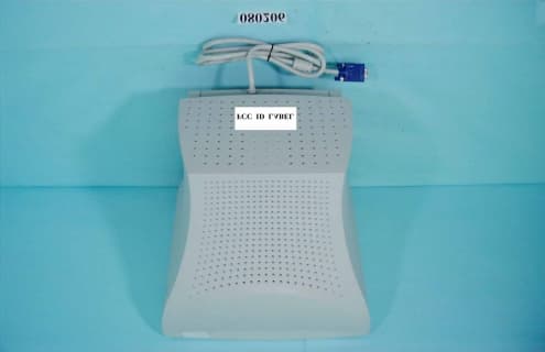
Click to zoom
Application Details
- Equipment Class
- JBP - Part 15 Class B Computing Device Peripheral
- Date of Grant
- Aug 24, 2000
- Application Purpose
- Original Equipment
- Date of Application
- Aug 23, 2000
- Equipment Note
- Monitor
- Company
- Lite-on Technology Corp.
- Country
- Taiwan
Documents & Files
Document Text
Text extracted from the exhibit documents filed with the FCC. Open a document above to read the original.
Users Manual
i Contents 1 Using Your LE500 Monitor . . . . . . . . . . . . . . . . . . . . . . . . . . . . . . . . . . . . . . . 1 Safety precautions . . . . . . . . . . . . . . . . . . . . . . . . . . . . . . . . . . . . . . . . . . . . . . . . . . . 2 Setting up the monitor . . . . . . . . . . . . . . . . . . . . . . . . . . . . . . . . . . . . . . . . . . . . . . . . 3 Removing the base . . . . . . . . . . . . . . . . . . . . . . . . . . . . . . . . . . . . . . . . . . . . . . . 5 Starting the monitor . . . . . . . . . . . . . . . . . . . . . . . . . . . . . . . . . . . . . . . . . . . . . . . . . . 6 Adjusting display settings . . . . . . . . . . . . . . . . . . . . . . . . . . . . . . . . . . . . . . . . . . . . . 7 OSD options . . . . . . . . . . . . . . . . . . . . . . . . . . . . . . . . . . . . . . . . . . . . . . . . . . . . 8 Video modes . . . . . . . . . . . . . . . . . . . . . . . . . . . . . . . . . . . . . . . . . . . . . . . . . . . 10 Power management . . . . . . . . . . . . . . . . . . . . . . . . . . . . . . . . . . . . . . . . . . . . . . . . 11 ENERGY STAR . . . . . . . . . . . . . . . . . . . . . . . . . . . . . . . . . . . . . . . . . . . . . . . . 11 Energy declaration . . . . . . . . . . . . . . . . . . . . . . . . . . . . . . . . . . . . . . . . . . . . . . 11 Maintenance . . . . . . . . . . . . . . . . . . . . . . . . . . . . . . . . . . . . . . . . . . . . . . . . . . . . . . 12 Troubleshooting . . . . . . . . . . . . . . . . . . . . . . . . . . . . . . . . . . . . . . . . . . . . . . . . . . . . 13 No picture . . . . . . . . . . . . . . . . . . . . . . . . . . . . . . . . . . . . . . . . . . . . . . . . . . . . . 13 Picture is scrambled . . . . . . . . . . . . . . . . . . . . . . . . . . . . . . . . . . . . . . . . . . . . . 14 Display colors are wrong . . . . . . . . . . . . . . . . . . . . . . . . . . . . . . . . . . . . . . . . . 14 Picture is fuzzy . . . . . . . . . . . . . . . . . . . . . . . . . . . . . . . . . . . . . . . . . . . . . . . . . 15 Picture bounces, jitters, or has waves . . . . . . . . . . . . . . . . . . . . . . . . . . . . . . . 15 Picture has shadows or “ghosts” . . . . . . . . . . . . . . . . . . . . . . . . . . . . . . . . . . . 15 Color is not uniform . . . . . . . . . . . . . . . . . . . . . . . . . . . . . . . . . . . . . . . . . . . . . 16 Image is not sized or centered properly . . . . . . . . . . . . . . . . . . . . . . . . . . . . . . 16 Image cannot be adjusted full screen . . . . . . . . . . . . . . . . . . . . . . . . . . . . . . . 16 Specifications . . . . . . . . . . . . . . . . . . . . . . . . . . . . . . . . . . . . . . . . . . . . . . . . . . . . . . 17 2 Safety, Regulatory, and Legal Information . . . . . . . . . . . . . . . . . . . . . . 19 ii 1 1 Using Your LE500 Monitor This monitor provides high resolution performance and operates in a variety of video modes. The flat square tube design makes images easier to see. The Microprocessor-based On-Screen Display (OSD) controls let you adjust a variety of image settings. 2 Using Your LE500 Monitor Safety precautions n Read all instructions before using the monitor, and save them for later use. n Follow all warnings and instructions marked on the product. n To avoid electrical shock, never open the monitor case. n Never use the monitor if the power cable has been damaged. Do not allow anything to rest on the power cable. n The openings in the monitor cabinet are for ventilation. Do not block or cover these openings. Do not insert anything into these openings. If you put the monitor in a bookcase or some other enclosed space, be sure to leave space for ventilation. n Do not expose the monitor to rain or use near water. Turning on a monitor that has been exposed to moisture will cause damage. If the monitor gets wet, unplug it, and contact technical support. n This monitor is equipped with a 3-wire grounding-type plug as a safety feature. This plug will only fit into a grounding-type outlet. If you are unable to insert the plug into an outlet, contact an electrician to install the appropriate outlet. Do not try to remove any of the prongs. n If any problems occur, unplug the monitor and contact technical support. Setting up the monitor 3 Setting up the monitor Setting up the monitor consists of two procedures: attaching the base and connecting the monitor cables. If you are setting up your system for the first time, refer to the setup poster for more information about connecting additional peripherals. To attach the base: 1 Carefully set the monitor on its side with the bottom of the monitor facing you. 2 Hold the base so that the narrow end is pointed toward the back of the monitor. 3 Align the four hooks on the bottom of the base with the corresponding slots on the bottom of the monitor. 4 Slide the base toward the front of the monitor so that all hooks are securely in place. A retaining latch built into the base clicks into place when the base is correctly attached. 5 Carefully set the monitor upright and place the monitor on a sturdy, level surface. 4 Using Your LE500 Monitor To connect the power and video cables: 1 Position the monitor and the computer so that you can easily get at the back panel of each. Make sure all power cables can reach a properly grounded electrical outlet. A AC power connector B Video cable (permanently connected) 2 Connect the video cable to the matching blue video connector on the back of your computer. 3 Tighten the screws on the video cable connectors to keep them from coming loose. Tightening the screws also prevents radio and TV interference. 4 Connect the power cord that came with the monitor to the AC power connector at the back of the monitor. To maintain FCC standards, only use the cord that came with the monitor. 5 Plug the other end of the power cord into a properly grounded electrical outlet. Removing the base To remove the base: 1 Turn off the system, then disconnect the monitor’s video and power cables. 2 Carefully set the monitor on its side w…
Text truncated - open the document above for the full version.
Block Diagram
FCC ID : H4ILE500
Cover Letter(s)
FEDERAL COMMUNICATIONS COMMISSIONFCC ID:H4ILE500 Authorization and Evaluation Division 7435 Oakland Mills Road Columbia, MD 21046 U.S.A. Re: About the modification of Monitor Gentlemen: I, hereby, declare that all modification on the E.U.T., FCC ID: H4IEV700, will be added or layout on the mass production products. Modifications are shown as below: 1. VGA Cable add a core (As the photo No.2) 2. G4 wire add a core. (As the photo No.12) 3. G2 wire add a core. (As the photo No.12) 4. Add two wires from shield can to CRT GND wire. (As the photo No.10) 5. AC inlet GND wire add a core. (As the photo No.11) 6. G2 signal trace add a 100p/2KV capacitor. (As the photo No.12) 7. Arcing wire add a core. (As the photo No.10) 8. Add two cores at SDA, SCL assembly wires. (As the photo No.11) 9. R.G.B. assembly wires add a core. (As the photo No.11) Sincerely yours Douglas Yang Supervisior
External Photos
FCC ID : H4ILE500 FRONT SIDE OF EUT 080206-01.jpg FCC ID : H4ILE500 Rear side of EUT(Reference Modification No.1) 080206-03F.jpg 1
ID Label/Location Info
FCC ID : H4ILE500
ID Label/Location Info
FCC ID LOCATION 9o2501-3f.JPG
Internal Photos
FCC ID : H4ILE500Mechanical Construction Number 3 080206-04DFK.jpg FCC ID : H4ILE500Mechanical Construction Number 4 080206-05DFK.jpg FCC ID : H4ILE500Mechanical Construction Number 5 080206-06DFK.jpg FCC ID : H4ILE500Mechanical Construction Number 6 080206-07DFK.jpg FCC ID : H4ILE500Mechanical Construction Number 7 080206-08DFK.jpg FCC ID : H4ILE500Front side of CRT Board Number 8 080206-09DFK.jpg FCC ID : H4ILE500Rear side of CRT board Number 9 080206-10DFK.jpg FCC ID : H4ILE500Mechanical Construction(Reference Modification No.5, No.8), Number 10 080206-11DFK.jpg 8 5 5 FCC ID : H4ILE500Front side of main board(Reference Modification No.6, No.9, No.10) Number 11 080206-12DFK.jpg 6 9 9 10 FCC ID : H4ILE500Front side of main board Number 12 080206-13DFK.jpg 7 3 4 FCC ID : H4ILE500Front side of main board Number 13 080206-14DFK.jpg FCC ID : H4ILE500Rear side of main board Number 14 080206-15DFK.jpg
Test Report
FCC TEST REPORT Report No. : F080206 SPORTON International Inc. FCC ID: H4ILE500 TEL : 886-2-2696-2468Page No.: 1 of 26 FAX : 886-2-2696-2255Issued Date : Aug. 9, 2000 FCC TEST REPORT for CISPR PUB. 22 Class B Equipment: 15”Monitor Model No.: LE500 FCC ID: H4ILE500 Filing Type: Original Grant Applicant: Lite-On Technology Corp. 5F, 16, Sec. 4, Nanking E. Rd., Taipei, Taiwan, R.O.C. ! The test result refers exclusively to the test presented test model / sample. ! Without the written authorization of the test lab., the Test Report may not be copied. ! Certificate or Test Report must not be used by the applicant to claim the product in this test report endorsement by NVLAP or any agency of U.S. government. SPORTON International Inc. 6F, No.106, Sec. 1, Hsin Tai Wu Rd., Hsi Chih, Taipei Hsien, Taiwan, R.O.C. FCC TEST REPORT Report No. : F080206 SPORTON International Inc. FCC ID: H4ILE500 TEL : 886-2-2696-2468Page No.: 2 of 26 FAX : 886-2-2696-2255Issued Date : Aug. 9, 2000 Table of Contents CERTIFICATE OF COMPLIANCE .............................................................................................................. 3 1. General Description of Equipment under Test..................................................................................... 4 1.1. Applicant .............................................................................................................................................................................................................. 4 1.2. Manufac turer ....................................................................................................................................................................................................... 4 1.3. Basic Description of Equipme nt under Test................................................................................................................................................... 4 1.4. Feature of Eq uipment under Tes t.................................................................................................................................................................... 4 2. Test Configuration of Equipment under Test....................................................................................... 6 2.1. Test Ma nner ........................................................................................................................................................................................................ 6 2.2. Description of Test S ystem............................................................................................................................................................................... 7 2.3. Connec tion Diagram o f Test Sys tem .............................................................................................................................................................. 9 3. Test Software ....................................................................................................................................... 9 4. General Information of Test ............................................................................................................... 11 4.1. Test Facility .......................................................................................................................................................................................................11 4.2. Standard for Methods o f Meas ure ment ........................................................................................................................................................11 4.3. Test in Comp liance with ..................................................................................................................................................................................11 4.4. Freque nc y Range Investigated ......................................................................................................................................................................11 4.5. Test Distance ....................................................................................................................................................................................................11 5. Test of Conducted Powerline............................................................................................................. 12 5.1. Major Measuring Instrume nts .........................................................................................................................................................................12 5.2. Test Procedures ...............................................................................................................................................................................................13 5.3. Typical Test Setup La yo ut o f Co nduc ted Powerline ...................................................................................................................................14 5.4. Test Res ult o f AC Powerline Cond ucted Emission.....................................................................................................................................15 5.5. Photograp hs o f Cond uc ted Powerline Tes t Configuration.........................................................................................................................17 6. Test of Radiated Emission.................................................................................................................. 17 6.1. Major Measuring Instrume nts .........................................................................................................................................................................19 6.2. Test Procedures ...............................................................................................................................................................................................20 6.3. Typical Test Setup La yo ut o f Radiated Emissio…
Text truncated - open the document above for the full version.
Test Setup Photos
1.1. Photographs of Conducted Powerline Test Configuration ! The photographs show the configuration that generates the maximum emission. FRONT VIEW REAR VIEW SIDE VIEW
Test Setup Photos
1.1. Photographs of Radiated Emission Test Configuration ! The photographs show the configuration that generates the maximum emission. FRONT VIEW REAR VIEW
Contact Information
Applicant
Chris Chuang(Engineer)
Test Firm
Sporton International Inc.W. Huang
Technical Specifications
| # | Rule Parts | Frequency Range | Power Output |
|---|---|---|---|
| 1 | 15B | - | - |
Other Applications from Lite-on Technology Corp.
H4ISK2186
Dec 23, 2025Wireless Keyboard
Equipment Class
DXX - Part 15 Low Power Communication Device TransmitterH4ISM2186
Nov 19, 2025Wireless Mouse
Equipment Class
DXX - Part 15 Low Power Communication Device TransmitterH4IKB555
Mar 27, 2024Wireless Keyboard
Equipment Class
DTS - Digital Transmission System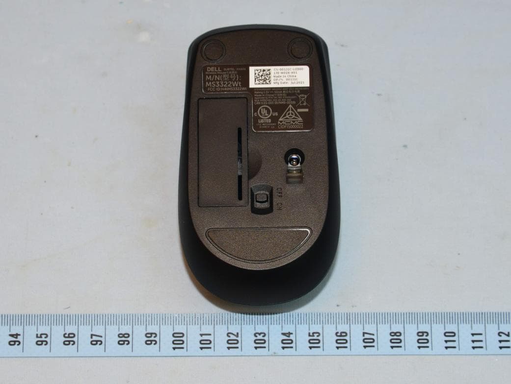
H4IWM118
Aug 25, 2021Wireless Mouse
Equipment Class
DTS - Digital Transmission System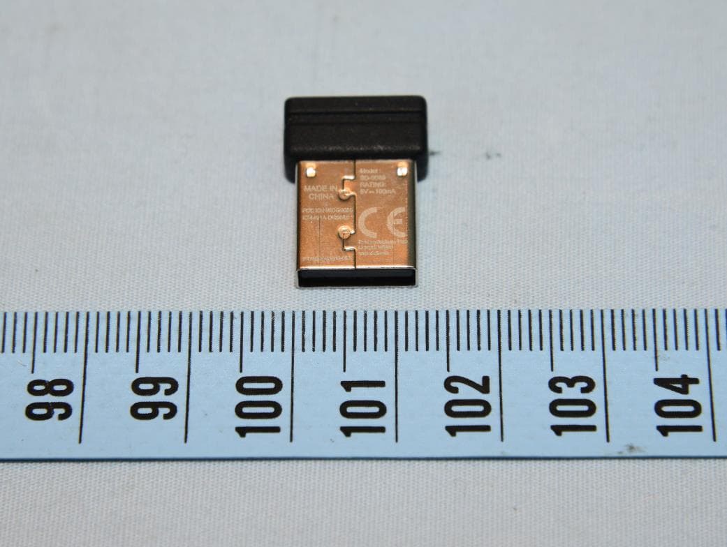
H4IUD2203
Aug 24, 2021Dongle
Equipment Class
DTS - Digital Transmission System