H4IPR24RF001Presenter
Lite-on Technology Corp.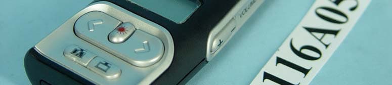
Click to zoom
Application Details
- Equipment Class
- DTS - Digital Transmission System
- Date of Grant
- Dec 20, 2004
- Application Purpose
- Original Equipment
- Date of Application
- Dec 20, 2004
- Equipment Note
- Presenter
- Frequency Range
- 2402.00000000 - 2479.00000000
- Company
- Lite-on Technology Corp.
- Country
- Taiwan
Documents & Files
Document Text
Text extracted from the exhibit documents filed with the FCC. Open a document above to read the original.
Users Manual
Lite-On technology corp. Confidential SM-2065 第 1 頁,共 5 頁 User’s Manual Model: R-RB5;C-UR37 Version : 0.3 Issue Date : DEC.21. 2004 Prepared By: Muchuan Lee Lite-On technology corp. Confidential SM-2065 第 2 頁,共 5 頁 1.Feature R-RB5;C-UR37 is a wireless product, It is very useful tool for presentation.R-RB5 is a receiver. Basically R-RB5 is a remote controller and we called it “Presenter”. This product operate at 2.4 GHz frequency. End- user use this product can easy to control Microsoft PowerPoint software. Receiver (C-UR37) is use USB(Universal Serial BUS) interface to connect with computer . R-RB5 is a remote controller to control Microsoft PowerPoint software. It has 6 buttons to control Microsoft PowerPoint software. These buttons are : 1. Start/Stop : Play and Stop 2. Black Screen: Disable the screen 3. Backward: Previous page 4. Forward: Next page 5. Volume UP: .To increase speaker volume. 6. Volume Down: To reduce speaker volume. Below 6 buttons must operate at Microsoft Power point software. z Laser Button: When we press this button , the presenter will launch laser light , this light will help audience to understand presentation materials. z Stop/Watch Button: When we press this button , the presenter will set up LCD display ‘s timer, The timer will count sown automatically, if timer remain 5 & 3 &1 & 0 minutes , presenter’s vibrator will vibrate to remind user. z Reset Button: The user need press this button to pair receiver(R-RB5), because presenter and Receiver must to pair successfully then they can work at the same frequency. z LCD display: It will show the timer (number and indicate bar) and battery status icon. 2.Setup: 1. The user must put 2-AAA batteries into presenter. 2. Turn on On/Off switch. Lite-On technology corp. Confidential SM-2065 第 3 頁,共 5 頁 3. Plug in Receiver into computer USB port. 4. Execute pairing software, it will attaché in product package. 5. Press Presenter’s reset button then software will show succeed message. 6. Execute Microsoft PowerPoint software. Pairing software’s windows 3.Product Outline *Product Outline: Binding timer(time out: 15 ) Exit bind AP Trigger button of bi d Lite-On technology corp. Confidential SM-2065 第 4 頁,共 5 頁 4 Electrical Specification 4.1 Presenter Power Consumption TX Operation Voltage: Voltage supplied to presenter : 3 VDC (AAA battery *2) TX Operation Current: Presenter : Under 3 VDC power supplied ,typical current is 18mA. Maximum current of Pairing : 150mA Typical power consumption of Presenter will be less than 40mW. Laser Point current : 25~45 mA, Laser output power : under 1mW (Class II) 4.2 Dongle Operating voltage Voltage supplied to Receiver: 5±0.25 VDC Current consumption :Under nominal 5 VDC power supplied, typical current Operating is 70 mA, 90 mA Maximum . 5 Dongle Cabel The Dongle don’t need use shielding cable that just directly insert to PC host. Lite-On technology corp. Confidential SM-2065 第 5 頁,共 5 頁 Federal Communication Commission Interference Statement This equipment has been tested and found to comply with the limits for a Class B digital device, pursuant to Part 15 of the FCC Rules. These limits are designed to provide reasonable protection against harmful interference in a residential installation. This equipment generates, uses and can radiate radio frequency energy and, if not installed and used in accordance with the instructions, may cause harmful interference to radio communications. However, there is no guarantee that interference will not occur in a particular installation. If this equipment does cause harmful interference to radio or television reception, which can be determined by turning the equipment off and on, the user is encouraged to try to correct the interference by one of the following measures: - Reorient or relocate the receiving antenna. - Increase the separation between the equipment and receiver. - Connect the equipment into an outlet on a circuit different from that to which the receiver is connected. - Consult the dealer or an experienced radio/TV technician for help. This device complies with Part 15 of the FCC Rules. Operation is subject to the following two conditions: (1) This device may not cause harmful interference, and (2) this device must accept any interference received, including interference that may cause undesired operation. FCC Caution: Any changes or modifications not expressly approved by the party responsible for compliance could void the user's authority to operate this equipment. IMPORTANT NOTE: FCC Radiation Exposure Statement: This equipment complies with FCC radiation exposure limits set forth for an uncontrolled environment. End users must follow the specific operating instructions for satisfying RF exposure compliance. This transmitter must not be co-located or operating in conjunction with any other antenna or transmitter. ------End of User’s Manual-------
External Photos
Page 1 CONSTRUCTION PHOTOS OF EUT
Internal Photos
Page 2 Page 3 Page 4 Page 5 Page 6 Page 7 Page 8 Page 9 Page 10
Operational Description
FCC ID: H4IPR24RF001 Report No.: RF931116A05 Operational Description This device is a Presenter which operates in the 2.4GHz frequency spectrum This device is a Frequency Hopping device with 79 hopping frequencies. The antenna type is printed antenna and there is no antenna connector used. The other instruction, please have a look at the users manual.
RF Exposure Info
FCC ID: H4IPR24RF001 Report No: SA931116A05 1 RF EXPOSURE REPORT REPORT NO.: SA931116A05 MODEL NO.: R-RB5 ACCORDING: FCC Guidelines for Human Exposure IEEE C95.1 APPLICANT: Lite-On Technology Corporation ADDRESS: 5F, 16, Sec 4, Nanking E. Road, Taipei, Taiwan, R.O.C. ISSUED BY: Advance Data Technology Corporation TEST LOCATION: No. 19, Hwa Ya 2nd Rd., Wen Hwa Tsuen, Kwei Shan Hsiang, Taoyuan Hsien 333, Taiwan, R.O.C. FCC ID: H4IPR24RF001 Report No: SA931116A05 2 RF Exposure Measurement (Portable Device) 1. Introduction In this document, we try to prove the safety of radiation harmfulness to the human body for our product. The limit for Maximum Permissible Exposure (MPE) specified in FCC 1.1310 is followed. The Gain of the antenna used in this product is measured in a Fully Anechoic Chamber (FAC) calibrated for antenna measurement in ADT, and also the maximum total power input to the antenna is measured. Through the Friis transmission formula and the maximum gain of the antenna, we can calculate the distance, away from the product, where the limit of MPE is reached. Although the Friis transmission formula is a far field assumption, the calculated result of that is an over-prediction for near field power density. We will take that as the worst case to specify the safety range. 2. RF Exposure Limit According to FCC 1.1310: The criteria listed in the following table shall be used to evaluate the environmental impact of human exposure to radio-frequency (RF) radiation as specified in 1.1307(b) LIMITS FOR MAXIMUM PERMISSIBLE EXPOSURE (MPE) Frequency Range (MHz) Electric Field Strength (V/m) Magnetic Field Strength (A/m) Power Density (mW/cm 2 ) Average Time (minutes) (A)Limits For Occupational / Control Exposures 300-1500......F/3006 1500-100,000......56 (B)Limits For General Population / Uncontrolled Exposure 300-1500......F/15006 1500-100,000......1.030 F = Frequency in MHz FCC ID: H4IPR24RF001 Report No: SA931116A05 3 3. Friis Formula Friis transmission formula: Pd = (Pout*G) / (4*pi*r 2 ) where Pd = power density in mW/cm 2 Pout = output power to antenna in mW G = gain of antenna in linear scale Pi = 3.1416 R = distance between observation point and center of the radiator in cm If we know the maximum Gain of the antenna and the total power input to the antenna, through the calculation, we will know the MPE value at distance 20cm. Ref.: David K. Cheng, Field and Wave Electromagnetics, Second Edition, Page 640, Eq. (11-133). 4 EUT Operating condition The software provided by Manufacturer enabled the EUT to transmit and receive data at lowest, middle and highest channel individually. 5. Classification This device is not fixed inside the host equipment that is classified as Portable Device. FCC ID: H4IPR24RF001 Report No: SA931116A05 4 6 Conclusion No Evaluation Required if power is below this threshold: F(GHz)mW Low2.402 High2.479 24.585 Maximum measured transmitter power: Pout (dBm)Pout (mW) Conducted Power-1.980.634 EIRP Power-7.400.182 *Note: The antenna is Chip antenna with –5.42dBi gain Threshold for no SAR evaluation is 24.585mW Transmitter power is 0.634mW Conclusion: No SAR evaluation required since Transmitter Pout is below FCC threshold
Test Report
FCC ID: H4IPR24RF001 Report No.: RF931116A051Issued: Nov. 26, 2004 FCC TEST REPORT REPORT NO. : RF931116A05 MODEL NO. : R-RB5 RECEIVED : Nov. 16, 2004 TESTED : Nov. 23 ~ Nov. 26, 2004 APPLICANT : Lite-On Technology Corporation ADDRESS : 5F, 16, Sec 4, Nanking E. Road, Taipei, Taiwan, R.O.C. ISSUED BY : Advance Data Technology Corporation LAB ADDRESS : No. 47, 14th Ling, Chia Pau Tsuen, Lin Kou Hsiang 244, Taipei Hsien, Taiwan, R.O.C. TEST LOCATION : No. 19, Hwa Ya 2nd Rd., Wen Hwa Tsuen, Kwei Shan Hsiang, Taoyuan Hsien 333, Taiwan, R.O.C. This test report consists of 55 pages in total. It may be duplicated completely for legal use with the approval of the applicant. It should not be reproduced except in full, without the written approval of our laboratory. The client should not use it to claim product endorsement by CNLA, A2LA or any government agencies. The test results in the report only apply to the tested sample. 0528 ILAC MR A No. 2177-01 FCC ID: H4IPR24RF001 Report No.: RF931116A052Issued: Nov. 26, 2004 Table of Contents 1CERTIFICATION ...................................................................................................4 2SUMMARY OF TEST RESULTS ...........................................................................5 2.1MEASUREMENT UNCERTAINTY.........................................................................5 3GENERAL INFORMATION....................................................................................6 3.1GENERAL DESCRIPTION OF EUT ......................................................................6 3.2DESCRIPTION OF TEST MODES ........................................................................7 3.3GENERAL DESCRIPTION OF APPLIED STANDARDS .......................................8 3.4DESCRIPTION OF SUPPORT UNITS ..................................................................9 3.5CONFIGURATION OF SYSTEM UNDER TEST...................................................9 4TEST TYPES AND RESULTS .............................................................................10 4.1RADIATED EMISSION MEASUREMENT ...........................................................10 4.1.1LIMITS OF RADIATED EMISSION MEASUREMENT.........................................10 4.1.2TEST INSTRUMENTS......................................................................................... 11 4.1.3TEST PROCEDURES .........................................................................................12 4.1.4DEVIATION FROM TEST STANDARD ...............................................................12 4.1.5TEST SETUP.......................................................................................................13 4.1.6EUT OPERATING CONDITIONS ........................................................................13 4.1.7TEST RESULTS (A) ............................................................................................14 4.1.8TEST RESULTS (B) ............................................................................................19 4.1.9TEST RESULTS (C) ............................................................................................24 4.26dB BANDWIDTH MEASUREMENT...................................................................29 4.2.1LIMITS OF 6dB BANDWIDTH MEASUREMENT ................................................29 4.2.2TEST INSTRUMENTS.........................................................................................29 4.2.3TEST PROCEDURE............................................................................................30 4.2.4DEVIATION FROM TEST STANDARD ...............................................................30 4.2.5TEST SETUP.......................................................................................................30 4.2.6EUT OPERATING CONDITIONS ........................................................................30 4.2.7TEST RESULTS ..................................................................................................31 4.3MAXIMUM PEAK OUTPUT POWER ..................................................................35 4.3.1LIMITS OF MAXIMUM PEAK OUTPUT POWER MEASUREMENT ...................35 4.3.2TEST INSTRUMENTS.........................................................................................35 FCC ID: H4IPR24RF001 Report No.: RF931116A053Issued: Nov. 26, 2004 4.3.3TEST PROCEDURES .........................................................................................35 4.3.4DEVIATION FROM TEST STANDARD ...............................................................36 4.3.5TEST SETUP.......................................................................................................36 4.3.6EUT OPERATING CONDITIONS ........................................................................36 4.3.7TEST RESULTS ..................................................................................................37 4.4POWER SPECTRAL DENSITY MEASUREMENT..............................................38 4.4.1LIMITS OF POWER SPECTRAL DENSITY MEASUREMENT ...........................38 4.4.2TEST INSTRUMENTS.........................................................................................38 4.4.3TEST PROCEDURE............................................................................................38 4.4.4DEVIATION FROM TEST STANDARD ...............................................................38 4.4.5TEST SETUP.......................................................................................................39 4.4.6EUT OPERATING CONDITIONS ........................................................................39 4.4.7TEST RESULTS ..................................................................................................40 4.5BAND EDGES MEASUREMENT ........................................................................44 4.5.1LIMITS OF BAND EDGES MEASUREMENT......................................................44 4.5.2TEST INSTRUMENTS..................................…
Text truncated - open the document above for the full version.
Test Setup Photos
FCC ID: H4IPR24RF001 Report No.: RF931116A0552Issued: Nov. 26, 2004 5 PHOTOGRAPHS OF THE TEST CONFIGURATION RADIATED EMISSION TEST (X axis) FCC ID: H4IPR24RF001 Report No.: RF931116A0553Issued: Nov. 26, 2004 RADIATED EMISSION TEST (Y axis) FCC ID: H4IPR24RF001 Report No.: RF931116A0554Issued: Nov. 26, 2004 RADIATED EMISSION TEST (Z axis)
Contact Information
Applicant
Chris Chuang(Engineer)
Technical Contact
Advance Data Technology Corp.Ellis Wu
[email protected]+886-3-318-3232
No.19, Hwa Ya 2nd Rd. · Taoyuan · Taiwan
Test Firm
Advance Data Technology CorporationStephen Chen
Technical Specifications
| # | Rule Parts | Frequency Range | Power Output |
|---|---|---|---|
| 1 | 15C | 2.40 GHz - 2.48 GHz | 600.00 µW |
Other Applications from Lite-on Technology Corp.
H4ISK2186
Dec 23, 2025Wireless Keyboard
Equipment Class
DXX - Part 15 Low Power Communication Device TransmitterH4ISM2186
Nov 19, 2025Wireless Mouse
Equipment Class
DXX - Part 15 Low Power Communication Device TransmitterH4IKB555
Mar 27, 2024Wireless Keyboard
Equipment Class
DTS - Digital Transmission System
H4IWM118
Aug 25, 2021Wireless Mouse
Equipment Class
DTS - Digital Transmission System
H4IUD2203
Aug 24, 2021Dongle
Equipment Class
DTS - Digital Transmission System