H79D85YYYYYYDLP Projector
Delta Electronics Incorporated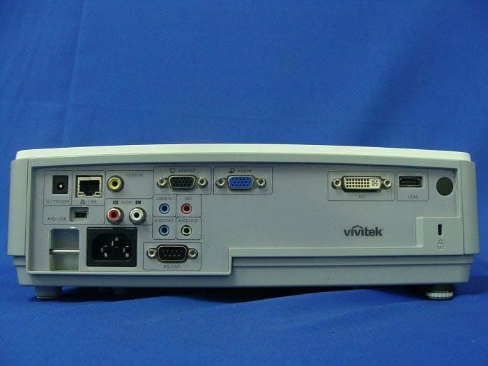
Click to zoom
Application Details
- Equipment Class
- DTS - Digital Transmission System
- Date of Grant
- Jun 14, 2012
- Application Purpose
- Original Equipment
- Date of Application
- Jun 13, 2012
- Equipment Note
- DLP Projector
- Frequency Range
- 2401.00000000 - 2481.00000000
- Country
- Taiwan
Documents & Files
Document Text
Text extracted from the exhibit documents filed with the FCC. Open a document above to read the original.
Users Manual
Copyright This publication, including all photographs, illustrations and software, is protected under international copy- right laws, with all rights reserved. Neither this manual, nor any of the material contained herein, may be reproduced without written consent of the author. © Copyright 2012 Disclaimer The information in this document is subject to change without notice. The manufacturer makes no repre- sentations or warranties with respect to the contents hereof and specifically disclaims any implied warranties of merchantability or fitness for any particular purpose. The manufacturer reserves the right to revise this publication and to make changes from time to time in the content hereof without obligation of the manufacturer to notify any person of such revision or changes. Trademark Recognition Kensington is a U.S. registered trademark of ACCO Brand Corporation with issued registrations and pend- ing applications in other countries throughout the world. HDMI, the HDMI Logo, and High-Definition Multimedia Interface are trademarks or registered trademarks of HDMI Licensing LLC in the United States and other countries. All other product names used in this manual are the properties of their respective owners and are ac- knowledged. — i — DLP Projector—User’s Manual — ii — Important Safety Information Important: It is strongly recommended that you read this section carefully before using the projector. These safety and usage instructions will ensure that you enjoy many years of safe use of the projector. Keep this manual for future reference. Symbols Used Warning symbols are used on the unit and in this manual to alert you of hazardous situations. The following styles are used in this manual to alert you to important information. Note: Provides additional information on the topic at hand. Important: Provides additional information that should not be overlooked. Caution: Alerts you to situations that may damage the unit. Warning: Alerts you to situations that may damage the unit, create a hazardous environment, or cause per- sonal injury. Throughout this manual, component parts and items in the OSD menus are denoted in bold font as in this example: “Push the Menu button on the remote control to open the Main menu.” General Safety Information ¾ Do not open the unit case. Aside from the projection lamp, there are no user-serviceable parts in the unit. For servicing, contact qualified service personnel. ¾ Follow all warnings and cautions in this manual and on the unit case. ¾ The projection lamp is extremely bright by design. To avoid damage to eyes, do not look into the lens when the lamp is on. ¾ Do not place the unit on an unstable surface, cart, or stand. ¾ Avoid using the system near water, in direct sunlight, or near a heating device. ¾ Do not place heavy objects such as books or bags on the unit. Preface Projector Installation Notice ¾ Place the projector in a horizontal position The tilt angle of the projector should not exceed 15 degrees, nor should the projector be in- stalled in any way other than the desktop and ceiling mount, otherwise lamp life could decrease dramatically, and may lead to other unpredictable damages. ¾ Allow at least 50 cm clearance around the exhaust vent. ¾ Ensure that the intake vents do not recycle hot air from the exhaust vent. ¾ When operating the projector in an enclosed space, ensure that the surrounding air temperature within the enclosure does not exceed operation temperaturewhile the projector is running, and the air intake and exhaust vents are unobstructed. ¾ All enclosures should pass a certified thermal evaluation to ensure that the projector does not recycle exhaust air, as this may cause the device to shutdown even if the enclosure temperature is with the acceptable operation temperature range. – iii – DLP Projector—User’s Manual — iv — Verify Installation Location ¾ Verify if the voltage is stable, grounded properly and there is no electricity leakage. ¾ Measure total power consumption which should not higher the safety capacity and avoid safety is- sue and short circuit. ¾ Turn on Altitude Mode when located in high altitude areas ¾ The projector can only be installed upright or inverted. ¾ When installation the bracket, make sure the weight limit is not exceed and firmly secured. ¾ Avoid installing near air conditioner duct or subwoofer. ¾ Avoid installing at high temperature, insufficient cooling and heavy dust locations. ¾ Keep your product away from fluorescent lamps to avoid malfunction caused by IR interference ¾ Install the projector above 200cm to avoid damage. Cooling notes Air outlet ¾ Make sure the air outlet is 50cm clear of any obstruction to ensure proper cooling. ¾ Air outlet location should not be in front of the lens of other projector to avoid causing illusions. ¾ Keep the outlet at least 100cm away from the inlets of other projectors Air inlet ¾ Make sure there is no object blocking air input within 30 cm. ¾ Keep the inlet away from other heat sources ¾ Avoided heavy dust area Choosing a Projector Edge blending application Not only brightness, bright balances, lens but stability is important too when choosing a projector. ¾ A projector need 30 to 60 minutes warm up to adjust properly. ¾ After lens shift, there should not be any optical distortion such as trapezoidal and barrel shape dis- tortions. ¾ Quick dis-assemble lens need to be firmly secured, the electric motor cannot be mistakenly shift. The screen should not be offset for long time use or during booting up and shutting down the pro- jector. ¾ Projector six-axis colors (R,G,B,Y,C,W). Projector adjust functions require: Hue, Saturation, Gain ¾ Vertical or 360 degree projection application. Needs to VERIFY engineering design of lamp aging to avoid conflict with client. HDMI Cable Edge blending signal needs to use digital transfer, the 4 pairs of TMDS transfer impedance require 100 Ω diameter as following to maintain signal quality: ¾ 5 M : AWG 26 ¾ 10 M : AWG 24 ¾ 1…
Text truncated - open the document above for the full version.
Cover Letter(s)
DELTA ELECTRONICS, INC. FCC ID.: H79D85YYYYYY 3 Tungyuan Road Chungli Industrial Zone Taoyuan County 32063, Taiwan. Tel : 886 3 4526107 DELTA ELECTRONICS, INC. 3 Tungyuan Road Chungli Industrial Zone Taoyuan County 32063, Taiwan. Tel : 886 3 4526107 Fax: 886 3 4528707 Federal Communications Commission June. 11., 2012 Authorization and Evaluation Division Confidentiality Request Pursuant to Sections 0.457 and 0.459 of the Commission’s Rules, the Applicant Hereby requests confidential treatment of information accompanying this Application As outlined below: Schematics: (D85yyyyyy) Schem Block Diagram: (D85yyyyyy) BlkDia Operational Description: (D85yyyyyy) OPDes The above materials contain trade secrets and proprietary information not customarily Released to the public. The public disclosure of these matters might be harmful to the Applicant and provide unjustified benefits to its competitors. The Applicant understands that pursuant to Rule 0.457, disclosure of this Application and all accompanying documentation will not be made before the date of the Grant for this application. Sincerely, ---------------------------------------------------- Ray Chen / Manager DELTA ELECTRONICS, INC.
External Photos
Report No.: 124463R-RFUSP42V01 Page : 1 of 8 Attachment 2 : EUT Detailed Photographs (1) EUT Photo (2) EUT Photo Report No.: 124463R-RFUSP42V01 Page : 2 of 8 (3) EUT Photo (4) EUT Photo
ID Label/Location Info
DELTA ELECTRONICS, INC. FCC ID.: H79D85YYYYYY 3 Tungyuan Road Chungli Industrial Zone Taoyuan County 32063, Taiwan Tel : 886 3 4526107 The FCC ID and will be placed on the equipment as shown in the photograph below.
ID Label/Location Info
DELTA ELECTRONICS, INC. FCC ID.: H79D85YYYYYY 3 Tungyuan Road Chungli Industrial Zone Taoyuan County 32063, Taiwan Tel : 886 3 4526107 FCC ID Label
Internal Photos
Report No.: 124463R-RFUSP42V01 Page : 3 of 8 (5) EUT Photo (6) EUT Photo Report No.: 124463R-RFUSP42V01 Page : 4 of 8 (7) EUT Photo (8) EUT Photo Report No.: 124463R-RFUSP42V01 Page : 5 of 8 (9) EUT Photo (10) EUT Photo Report No.: 124463R-RFUSP42V01 Page : 6 of 8 (11) EUT Photo (12) EUT Photo Report No.: 124463R-RFUSP42V01 Page : 7 of 8 (13) EUT Photo (14) EUT Photo Report No.: 124463R-RFUSP42V01 Page : 8 of 8 (15) EUT Photo (16) EUT Photo
RF Exposure Info
Report No. 124463R-RFUSP42V01 Page: 1 of 3 RF Exposure Evaluation declaration Product Name DLP Projector Model No. D85yyyyyy ( y can be any character or blank) FCC ID H79D85YYYYYY Applicant DELTA ELECTRONICS, INC. Address 3 Tungyuan Road Chungli Industrial Zone Taoyuan County 32063, Taiwan. Date of Receipt Apr. 23, 2012 Date of DeclarationMay. 23, 2012 Report No. 124463R-RFUSP42V01 The declaration results relate only to the samples calculated. The declaration shall not be reproduced except in full without the written approval of QuieTek Corporation. This report must not be used to claim product endorsement by NVLAP any agency of the U.S. Government Report No. 124463R-RFUSP42V01 Page: 2 of 3 1. RF Exposure Evaluation 1.1. Limits According to FCC 1.1310: The criteria listed in the following table shall be used to evaluate the environment impact of human exposure to radio frequency (RF) radiation as specified in 1.1307(b) LIMITS FOR MAXIMUM PERMISSIBLE EXPOSURE (MPE) Frequency Range (MHz) Electric Field Strength (V/m) Magnetic Field Strength (A/m) Power Density (mW/cm 2 ) Average Time (Minutes) (A) Limits for Occupational/ Control Exposures 300-1500 -- -- F/300 6 1500-100,000 -- -- 5 6 (B) Limits for General Population/ Uncontrolled Exposures 300-1500 -- -- F/1500 6 1500-100,000 -- -- 1 30 F= Frequency in MHz Friis Formula Friis transmission formula: Pd = (Pout*G)/(4*pi*r 2 ) Where Pd = power density in mW/cm 2 Pout = output power to antenna in mW G = gain of antenna in linear scale Pi = 3.1416 R = distance between observation point and center of the radiator in cm Pd id the limit of MPE, 1 mW/cm 2 . If we know the maximum gain of the antenna and the total power input to the antenna, through the calculation, we will know the distance r where the MPE limit is reached. 1.2. Test Procedure Software provided by client enabled the EUT to transmit and receive data at lowest, middle and highest channel individually. The temperature and related humidity: 18°Cand 78% RH. Report No. 124463R-RFUSP42V01 Page: 3 of 3 1.3. Test Result of RF Exposure Evaluation Product : DLP Projector Test Item : RF Exposure Evaluation Test Site : No.3 OATS Antenna Gain Antenna Gain: The maximum Gain measured in fully anechoic chamber is 2.85 dBi in logarithm scale. Output Power Into Antenna & RF Exposure Evaluation Distance (2.85 dBi): Channel Frequency (MHz) Output Power to Antenna (mW) Power Density at R = 20 cm (mW/cm2) 01 2401.00 0.3148 0.000121 16 2448.00 0.3319 0.000127 29 2481.00 0.3954 0.000152 Power density in column 4 is much lower than the limit (1 mW/cm 2 ).
Test Report
Report No. 124463R-RFUSP42V01 Page : 1 of 58 Test Report Product Name DLP Projector Model No D85yyyyyy ( y can be any character or blank) FCC ID. H79D85YYYYYY Applicant DELTA ELECTRONICS, INC. Address 3 Tungyuan Road Chungli Industrial Zone Taoyuan County 32063, Taiwan. Date of Receipt Apr. 23, 2012 Issue Date May. 23, 2012 Report No. 124463R-RFUSP42V01 Report Version V1.0 The test results relate only to the samples tested. The test report shall not be reproduced except in full without the written approval of QuieTek Corporation. This report must not be used to claim product endorsement by NVLAP any agency of the U.S. Government Report No. 124463R-RFUSP42V01 Page : 2 of 58 Test Report Certification Issue Date: May. 23, 2012 Report No.: 124463R-RFUSP42V01 Product Name DLP Projector Applicant DELTA ELECTRONICS, INC. Address 3 Tungyuan Road Chungli Industrial Zone Taoyuan County 32063, Taiwan. Manufacturer DELTA ELECTRONICS, INC. Model No. D85yyyyyy ( y can be any character or blank) EUT Rated Voltage AC 100-240V,50-60Hz EUT Test Voltage AC 120V/ 60Hz Trade Name Vivitek Applicable Standard FCC CFR Title 47 Part 15 Subpart C: 2010 ANSI C63.4: 2003 Test Result Complied The test results relate only to the samples tested. The test report shall not be reproduced except in full without the written approval of QuieTek Corporation. This report must not be used to claim product endorsement by NVLAP any agency of the U.S. Government Documented By : (Senior Adm. Specialist / Leven Huang ) Tested By : (Assistant Engineer / Alan Chen ) Approved By : ( Manager / Vincent Lin) Accredited by NIST (NVLAP) NVLAP Lab Code: 200533-0 Report No. 124463R-RFUSP42V01 Page : 3 of 58 TABLE OF CONTENTS Description Page 1. GENERAL INFORMATION ............................................................................................ 5 1.1. EUT Description ............................................................................................................. 5 1.2. Operational Description .................................................................................................. 7 1.3. Tested System Details .................................................................................................... 8 1.4. Configuration of Tested System...................................................................................... 9 1.5. EUT Exercise Software .................................................................................................. 9 1.6. Test Facility...................................................................................................................10 2. Conducted Emission.................................................................................................. 11 2.1. Test Equipment............................................................................................................. 11 2.2. Test Setup .................................................................................................................... 11 2.3. Limits ............................................................................................................................ 12 2.4. Test Procedure ............................................................................................................. 12 2.5. Uncertainty ................................................................................................................... 12 2.6. Test Result of Conducted Emission.............................................................................. 13 3. Peak Power Output .................................................................................................... 15 3.1. Test Equipment............................................................................................................. 15 3.2. Test Setup .................................................................................................................... 15 3.3. Limit .............................................................................................................................. 15 3.4. Test Procedure ............................................................................................................. 15 3.5. Uncertainty ................................................................................................................... 15 3.6. Test Result of Peak Power Output ............................................................................... 16 4. Radiated Emission ..................................................................................................... 17 4.1. Test Equipment............................................................................................................. 17 4.2. Test Setup .................................................................................................................... 18 4.3. Limits ............................................................................................................................ 19 4.4. Test Procedure ............................................................................................................. 19 4.5. Uncertainty ................................................................................................................... 19 4.6. Test Result of Radiated Emission................................................................................. 20 5. RF antenna conducted test ....................................................................................... 27 5.1. Test Equipment............................................................................................................. 27 5.2. Test Setup .................................................................................................................... 27 5.3. Limits ............................................................................................................................ 27 5.4. Test Procedure ...................................................................…
Text truncated - open the document above for the full version.
Test Setup Photos
Report No.: 124463R-RFUSP42V01 Page : 1 of 3 Attachment 1: EUT Test Setup Photographs Front View of Conducted Test Back View of Conducted Test Report No.: 124463R-RFUSP42V01 Page : 2 of 3 Front View of Radiated Test Back View of Radiated Test Report No.: 124463R-RFUSP42V01 Page : 3 of 3 Front View of Radiated Test (Horn) Back View of Radiated Test (Horn)
Contact Information
Applicant
Ray Chen(Manager)
Technical Contact
QuieTek CorporationVincent Lin
[email protected]886-2-8601-3788
No.5-22, Ruishukeng, Linkou Dist., · Taiwan
Non-Technical Contact
QuieTek CorporationSabina Chen
Test Firm
DEKRA TESTING AND CERTIFICATION CO., LTD.Warren Lin
Technical Specifications
| # | Rule Parts | Frequency Range | Power Output |
|---|---|---|---|
| 1 | 15C | 2.40 GHz - 2.48 GHz | 400.00 µW |
Other Applications from Delta Electronics Incorporated

H79-023DS3
Jul 26, 2023NovoDS Digital Signage Solution
Equipment Class
DTS - Digital Transmission System
H79-023DS2
Jul 25, 2023NovoDS Digital Signage Solution
Equipment Class
DTS - Digital Transmission System
H79VFRU-25-46BT
Sep 27, 2022SIG Bluetooth speaker
Equipment Class
DSS - Part 15 Spread Spectrum Transmitter
H79-UNOC07X011
Nov 25, 2020UNOnext Indoor Air Quality Monitor
Equipment Class
DTS - Digital Transmission System
H79-019NC9
Jul 12, 2020NovoConnect Wireless Collaboration System
Equipment Class
NII - Unlicensed National Information Infrastructure TX