H79DFZM-TS220ZigBee module
Delta Electronics Incorporated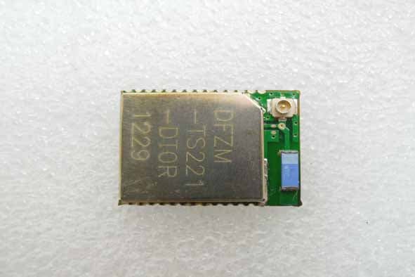
Click to zoom
Application Details
- Equipment Class
- DXX - Part 15 Low Power Communication Device Transmitter
- Date of Grant
- Sep 24, 2012
- Application Purpose
- Original Equipment
- Date of Application
- Sep 19, 2012
- Equipment Note
- ZigBee module
- Frequency Range
- 2405.00000000 - 2480.00000000
- Country
- Taiwan
Documents & Files
Document Text
Text extracted from the exhibit documents filed with the FCC. Open a document above to read the original.
Users Manual
D F Z M- T S 2 2 0 User Manual Sheet of 24 Sep. 5, 2012 Proprietary Information and Specifications are Subject to Change 1 User Manual DELTA DFZM-TS220 2.4GHz IEEE 802.15.4 Module D F Z M- T S 2 2 0 User Manual Sheet of 24 Sep. 5, 2012 Proprietary Information and Specifications are Subject to Change 2 1. DFZM-TS220/TS221 EVB This section describes the various interfaces and jumper settings for the DFZM-TS22x evaluation board. Description: 1 - 10 PIN F/W write connector (J3) 2 - DFZM-TS221 ZigBee module 3 – Power positive (Vcc) 4 - Power negative (Gnd) J3 connector pin out D F Z M- T S 2 2 0 User Manual Sheet of 24 Sep. 5, 2012 Proprietary Information and Specifications are Subject to Change 3 2. Updating the Firmware by the SmartRF EVB 1. Daughter Board 10 PIN Connector (J3) 2. SmartRF EVB 10 PIN Connector (P3 ExtSoC Debug) 3. TS221 module 4. TI 10 PIN cable (i.e. Daughter EVB need 3/3.3V) D F Z M- T S 2 2 0 User Manual Sheet of 24 Sep. 5, 2012 Proprietary Information and Specifications are Subject to Change 4 3. Updating the Firmware by the CC Debugger 1. CC Debugger 10PIN Connector 2. CC Debugger LED (If a module is detected, the LED will be GREEN. If no modules are detected, the LED will be RED) (i.e. Daughter Board don’t need 3/3.3V) Daughter EVB LEDs: D1: Power LED D2: Status LED (The LED is blinking while the firmware is being updated!) D F Z M- T S 2 2 0 User Manual Sheet of 24 Sep. 5, 2012 Proprietary Information and Specifications are Subject to Change 5 4. Installing USB driver To get the required USB driver for the CC Debugger, it is necessary to install one of the tools listed below: • • • • SmartRF Studio www.ti.com/tool/smartrftm-studio • • • • SmartRF Flash Programmer www.ti.com/tool/flash-programmer • • • • PurePath Wireless Configurator http://www.ti.com/tool/purepath-wl-cfg Alternatively, you can download “Cebal – CCxxxx Development Tools USB Driver for Windows x86 and x64” [3] which is a standalone installer including only the device driver. After having installed the driver, connect the CC Debugger to the PC. The USB driver will be installed automatically. You can quickly check that the debugger has been associated correctly with the USB device driver by opening the Windows Device Manager. The debugger should appear as a “Cabal controlled device”. Verify driver installation D F Z M- T S 2 2 0 User Manual Sheet of 24 Sep. 5, 2012 Proprietary Information and Specifications are Subject to Change 6 5. Start SmartRF Studio List of Connected devices The list of connected devices at the bottom of the startup panel shows the following information about each connected device: Evaluation board type, USB Device Identifier, Firmware revision and device type. The Device Control panel can also be started by clicking on one of the entries in the list of connected devices. The list of connected devices will normally be updated automatically when a USB device is connected. It is also possible to force update of the list by clicking on the "Refresh" button on the top right corner of the list. D F Z M- T S 2 2 0 User Manual Sheet of 24 Sep. 5, 2012 Proprietary Information and Specifications are Subject to Change 7 The SmartRF Studio Device Control Panel allows the operator to • execute test functions o packet RX o packet TX o continuous RX o continuous TX • select predefined (typical) settings • to view and adjust RF parameters • access individual registers via the Register View • select either a simple user interface (Easy Mode) or an advanced (Expert Mode) D F Z M- T S 2 2 0 User Manual Sheet of 24 Sep. 5, 2012 Proprietary Information and Specifications are Subject to Change 8 Easy Mode Easy Mode provides a simple user interface for packet transmission and reception. The user can select between two test modes; Packet TX and Packet RX in the bottom panel. Quick Start A packet TX/RX test between two devices can be started simply by selecting 'Packet TX' on one of the devices and 'Packet RX' on the other. Press start on the 'Packet RX' device first, then press start on the 'Packet TX' device to start the packet transmission. Select Configuration Select a configuration with the predefined protocol and packet format, data rate and frequency. Each configuration programs the connected device with a list of register values according to the configuration parameters. Make sure that the same configuration is used on both the transmitting and receiving device. Details of the selected packet format can be seen in either the 'Packet TX' or 'Packet RX' panels at the bottom of the screen. Expert Mode Expert Mode provides a more advanced user interface than Easy Mode. From the Expert Mode the user can change advanced RF parameters for the connected device. The expert mode includes a typical settings panel, an RF parameter panel and the following test function panels: Continuous TX, Continuous RX, Packet TX, Packet RX and RF Device Commands. The various panels visible from Expert Mode are described in the following sections. D F Z M- T S 2 2 0 User Manual Sheet of 24 Sep. 5, 2012 Proprietary Information and Specifications are Subject to Change 9 Typical settings The list of typical settings includes recommended register settings for some typically used parameter values. By selecting one of the typical settings the recommended register values for this combination of parameters will be programmed to the device. RF Parameters The RF parameters panel shows the current value of various RF parameters. The specific RF parameters shown in this panel is dependent to the connected device type. When a parameter value is changed by the user, new register values will be calculated D F Z M- T S 2 2 0 User Manual Sheet of 24 Sep. 5, 2012 Proprietary Information and Specifications are Subject to Change 10 and the register view is updated accordingly. If not operating in offline mode, the register values will also be written to the connected device. Likewise if a register value is changed, either from register view or …
Text truncated - open the document above for the full version.
Users Manual
D F Z M - T S 2 2 1 User Manual Sheet of 25 Sep. 5, 2012 Proprietary Information and Specifications are Subject to Change 1 User Manual DELTA DFZM-TS221 2.4GHz IEEE 802.15.4 Module D F Z M - T S 2 2 1 User Manual Sheet of 25 Sep. 5, 2012 Proprietary Information and Specifications are Subject to Change 2 1. DFZM-TS220/TS221 EVB This section describes the various interfaces and jumper settings for the DFZM-TS22x evaluation board. Description: 1 - 10 PIN F/W write connector (J3) 2 - DFZM-TS221 ZigBee module 3 – Power positive (Vcc) 4 - Power negative (Gnd) J3 connector pin out D F Z M - T S 2 2 1 User Manual Sheet of 25 Sep. 5, 2012 Proprietary Information and Specifications are Subject to Change 3 2. Updating the Firmware by the SmartRF EVB 1. Daughter Board 10 PIN Connector (J3) 2. SmartRF EVB 10 PIN Connector (P3 ExtSoC Debug) 3. TS221 module 4. TI 10 PIN cable (i.e. Daughter EVB need 3/3.3V) D F Z M - T S 2 2 1 User Manual Sheet of 25 Sep. 5, 2012 Proprietary Information and Specifications are Subject to Change 4 3. Updating the Firmware by the CC Debugger 1. CC Debugger 10PIN Connector 2. CC Debugger LED (If a module is detected, the LED will be GREEN. If no modules are detected, the LED will be RED) (i.e. Daughter Board don’t need 3/3.3V) Daughter EVB LEDs: D1: Power LED D2: Status LED (The LED is blinking while the firmware is being updated!) D F Z M - T S 2 2 1 User Manual Sheet of 25 Sep. 5, 2012 Proprietary Information and Specifications are Subject to Change 5 4. Installing USB driver To get the required USB driver for the CC Debugger, it is necessary to install one of the tools listed below: • • • • SmartRF Studio www.ti.com/tool/smartrftm-studio • • • • SmartRF Flash Programmer www.ti.com/tool/flash-programmer • • • • PurePath Wireless Configurator http://www.ti.com/tool/purepath-wl-cfg Alternatively, you can download “Cebal – CCxxxx Development Tools USB Driver for Windows x86 and x64” [3] which is a standalone installer including only the device driver. After having installed the driver, connect the CC Debugger to the PC. The USB driver will be installed automatically. You can quickly check that the debugger has been associated correctly with the USB device driver by opening the Windows Device Manager. The debugger should appear as a “Cabal controlled device”. Verify driver installation D F Z M - T S 2 2 1 User Manual Sheet of 25 Sep. 5, 2012 Proprietary Information and Specifications are Subject to Change 6 5. Start SmartRF Studio List of Connected devices The list of connected devices at the bottom of the startup panel shows the following information about each connected device: Evaluation board type, USB Device Identifier, Firmware revision and device type. The Device Control panel can also be started by clicking on one of the entries in the list of connected devices. The list of connected devices will normally be updated automatically when a USB device is connected. It is also possible to force update of the list by clicking on the "Refresh" button on the top right corner of the list. D F Z M - T S 2 2 1 User Manual Sheet of 25 Sep. 5, 2012 Proprietary Information and Specifications are Subject to Change 7 The SmartRF Studio Device Control Panel allows the operator to • execute test functions o packet RX o packet TX o continuous RX o continuous TX • select predefined (typical) settings • to view and adjust RF parameters • access individual registers via the Register View • select either a simple user interface (Easy Mode) or an advanced (Expert Mode) D F Z M - T S 2 2 1 User Manual Sheet of 25 Sep. 5, 2012 Proprietary Information and Specifications are Subject to Change 8 Easy Mode Easy Mode provides a simple user interface for packet transmission and reception. The user can select between two test modes; Packet TX and Packet RX in the bottom panel. Quick Start A packet TX/RX test between two devices can be started simply by selecting 'Packet TX' on one of the devices and 'Packet RX' on the other. Press start on the 'Packet RX' device first, then press start on the 'Packet TX' device to start the packet transmission. Select Configuration Select a configuration with the predefined protocol and packet format, data rate and frequency. Each configuration programs the connected device with a list of register values according to the configuration parameters. Make sure that the same configuration is used on both the transmitting and receiving device. Details of the selected packet format can be seen in either the 'Packet TX' or 'Packet RX' panels at the bottom of the screen. Expert Mode Expert Mode provides a more advanced user interface than Easy Mode. From the Expert Mode the user can change advanced RF parameters for the connected device. The expert mode includes a typical settings panel, an RF parameter panel and the following test function panels: Continuous TX, Continuous RX, Packet TX, Packet RX and RF Device Commands. The various panels visible from Expert Mode are described in the following sections. D F Z M - T S 2 2 1 User Manual Sheet of 25 Sep. 5, 2012 Proprietary Information and Specifications are Subject to Change 9 Typical settings The list of typical settings includes recommended register settings for some typically used parameter values. By selecting one of the typical settings the recommended register values for this combination of parameters will be programmed to the device. RF Parameters The RF parameters panel shows the current value of various RF parameters. The specific RF parameters shown in this panel is dependent to the connected device type. When a parameter value is changed by the user, new register values will be calculated D F Z M - T S 2 2 1 User Manual Sheet of 25 Sep. 5, 2012 Proprietary Information and Specifications are Subject to Change 10 and the register view is updated accordingly. If not operating in offline mode, the register values will also be written to the connected device. Likewise if a register value is changed, either from registe…
Text truncated - open the document above for the full version.
External Photos
Unless otherwise stated the results shown in this test report refer only to the sample(s) tested and such sample(s) are retained for 90 days only. 說留不 This document is issued by the Company subject to its General Conditions of Service printed overleaf, available on request or accessible at www.sgs.com/terms_and_conditions.htm and, for electronic format documents, subject to Terms and Conditions for Electronic Documents at www.sgs.com/terms_e-document.htm. Attention is drawn to the limitation of liability, indemnification and jurisdiction issues defined therein. Any holder of this document is advised that information contained hereon reflects the Company’s findings at the time of its intervention only and within the limits of Client’s instructions, if any. The Company’s sole responsibility is to its Client and this document does not exonerate parties to a transaction from exercising all their rights and obligations under the transaction documents. This document cannot be reproduced except in full, without prior written approval of the Company. Any unauthorized alteration, forgery or falsification of the content or appearance of this document is unlawful and offenders may be prosecuted to the fullest extent of the law. SGS Taiwan Ltd. No.134,WuKungRoad,NewTaipeiIndustrialPark,WukuDistrict,NewTaipeiCity,Taiwan24803/北北路134 t (8862) 22993279 f (8862) 22980488 www.tw.sgs.com Member of SGS Group FCC ID: H79DFZM-TS220 All of EUT (DFZM-TS220) All of EUT (DFZM-TS221)
Internal Photos
Unless otherwise stated the results shown in this test report refer only to the sample(s) tested and such sample(s) are retained for 90 days only. 說留不 This document is issued by the Company subject to its General Conditions of Service printed overleaf, available on request or accessible at www.sgs.com/terms_and_conditions.htm and, for electronic format documents, subject to Terms and Conditions for Electronic Documents at www.sgs.com/terms_e-document.htm. Attention is drawn to the limitation of liability, indemnification and jurisdiction issues defined therein. Any holder of this document is advised that information contained hereon reflects the Company’s findings at the time of its intervention only and within the limits of Client’s instructions, if any. The Company’s sole responsibility is to its Client and this document does not exonerate parties to a transaction from exercising all their rights and obligations under the transaction documents. This document cannot be reproduced except in full, without prior written approval of the Company. Any unauthorized alteration, forgery or falsification of the content or appearance of this document is unlawful and offenders may be prosecuted to the fullest extent of the law. SGS Taiwan Ltd. No.134,WuKungRoad,NewTaipeiIndustrialPark,WukuDistrict,NewTaipeiCity,Taiwan24803/北北路134 t (8862) 22993279 f (8862) 22980488 www.tw.sgs.com Member of SGS Group FCC ID: H79DFZM-TS220 Front View of EUT (DFZM-TS220) Front View of EUT (DFZM-TS221) Unless otherwise stated the results shown in this test report refer only to the sample(s) tested and such sample(s) are retained for 90 days only. 說留不 This document is issued by the Company subject to its General Conditions of Service printed overleaf, available on request or accessible at www.sgs.com/terms_and_conditions.htm and, for electronic format documents, subject to Terms and Conditions for Electronic Documents at www.sgs.com/terms_e-document.htm. Attention is drawn to the limitation of liability, indemnification and jurisdiction issues defined therein. Any holder of this document is advised that information contained hereon reflects the Company’s findings at the time of its intervention only and within the limits of Client’s instructions, if any. The Company’s sole responsibility is to its Client and this document does not exonerate parties to a transaction from exercising all their rights and obligations under the transaction documents. This document cannot be reproduced except in full, without prior written approval of the Company. Any unauthorized alteration, forgery or falsification of the content or appearance of this document is unlawful and offenders may be prosecuted to the fullest extent of the law. SGS Taiwan Ltd. No.134,WuKungRoad,NewTaipeiIndustrialPark,WukuDistrict,NewTaipeiCity,Taiwan24803/北北路134 t (8862) 22993279 f (8862) 22980488 www.tw.sgs.com Member of SGS Group FCC ID: H79DFZM-TS220 Back View of EUT(DFZM-TS220 & 221) Dipole Antenna for (DFZM-TS220) Unless otherwise stated the results shown in this test report refer only to the sample(s) tested and such sample(s) are retained for 90 days only. 說留不 This document is issued by the Company subject to its General Conditions of Service printed overleaf, available on request or accessible at www.sgs.com/terms_and_conditions.htm and, for electronic format documents, subject to Terms and Conditions for Electronic Documents at www.sgs.com/terms_e-document.htm. Attention is drawn to the limitation of liability, indemnification and jurisdiction issues defined therein. Any holder of this document is advised that information contained hereon reflects the Company’s findings at the time of its intervention only and within the limits of Client’s instructions, if any. The Company’s sole responsibility is to its Client and this document does not exonerate parties to a transaction from exercising all their rights and obligations under the transaction documents. This document cannot be reproduced except in full, without prior written approval of the Company. Any unauthorized alteration, forgery or falsification of the content or appearance of this document is unlawful and offenders may be prosecuted to the fullest extent of the law. SGS Taiwan Ltd. No.134,WuKungRoad,NewTaipeiIndustrialPark,WukuDistrict,NewTaipeiCity,Taiwan24803/北北路134 t (8862) 22993279 f (8862) 22980488 www.tw.sgs.com Member of SGS Group FCC ID: H79DFZM-TS220 Chip Antenna for (DFZM-TS221) ~ End of Report ~
Test Report
Rev. 3.0 AR007 WLAN Antenna Specification 1 / 3 Wellshow ® For more information, contact [email protected] TEL: +886 2-2427-0488 FAX: +886 2-2426-0387 9F., No.181, Nanrong Rd., Ren-ai Dist., Keelung City 200, Taiwan (R.O.C.) www.Wellshow.com www.wellshow.com www.rfcoaxcable.com For more information, contact [email protected] TEL: +886 2-2423-9376 FAX: +886 2-2426-0387 9F., No.181, Nanrong Rd., Ren-ai Dist., Keelung City 200, Taiwan (R.O.C.) 2.4GHz WLAN Antenna Swivel type with extended 1.13mm Cable and I-PEX Plug Product No. AR007WSW01A03 Structure Figure DescriptionSpecification Frequency Range2.4GHz Impedance50 Ω VSWR2.0 Max Return Loss- 10 dB Max Certain directionOmin Gain2 dBi DescriptionSpecification Antenna CoverTPEE (Black) Antenna HolderPC (Black) Antenna Base PBT (Black) Captive latchABS (Black) Operating Temperature-20°C~+65°C Storage Temperature -30°C~+75°C ConnectorI-PEX MHF Plug 20278-112R-13 (U.FL) Cable Type 1.13mm RF coaxial cable (Gray) L=100mm Electrical SpecificationMechanical Specification AR007 Antenna Captive latch for AR007 Antenna P/N W0V0054R007-01 Option CoverHolderBase Rev. 3.0 AR007 WLAN Antenna Specification 2 / 3 Wellshow ® For more information, contact [email protected] TEL: +886 2-2427-0488 FAX: +886 2-2426-0387 9F., No.181, Nanrong Rd., Ren-ai Dist., Keelung City 200, Taiwan (R.O.C.) www.Wellshow.com www.wellshow.com www.rfcoaxcable.com For more information, contact [email protected] TEL: +886 2-2423-9376 FAX: +886 2-2426-0387 9F., No.181, Nanrong Rd., Ren-ai Dist., Keelung City 200, Taiwan (R.O.C.) Test results Reture Loss VSWR Radiation Pattern of H Plane 2.4~2.5GHzRadiation Pattern of V Plane 2.4~2.5GHz
Test Report
NOTES : *1 Checked SUPPLIER : REV. SHEET A TO 1 File Name : FR1R00.XLS Approved WALSIN TECHNOLOGY CORPORATION 02/08/2006 Checked 00 台達電子工業股份有限公司 DELTA ELECTRONICS, INC. DESCRIPTION : ANTENNA DRAWING NO. : 0990165304 02/08/2006 REV. Description 00 ISSUE SPEC 02/08/2006 02/08/2006 Designed Drawn ITEM NOTES DELTA P/N SUPPLIER P/N Date 1 0990165304 RFANT5220110A0T *1 ANTENNA 2.4-2.5GHz 2dBi 2 H1.15 5.2 2008 02/08/2006 THESE DRAWINGS AND SPECIFICATIONS ARE THE PROPERTY OF DELTA ELECTRONICS ,INC. AND SHALL NOT BE REPRODUCED OR USED AS THE BASIS FOR THE MANUFACTUREOR SELL OF APPARATUSES OR DEVICES WITHOUT PERMISSION. Walsin Technology Corporation MULTILAYER CERAMIC ANTENNA RFANT Series 2.4 GHz ISM Band Working Frequency P/N: RFANT5220110A0T Page 1 of 16 AS_RFANT5220110A0T_0 Feb. 2003 Walsin Technology Corporation Page 2 of 16 AS_RFANT5220110A0T_03 Feb-2003 FEATURES Surface Mounted Devices with a small dimension of 5.2 x 2.0 x 1.1 mm 3 meet future miniaturization trend. Embedded and LTCC (Low Temperature Co-fired Ceramic) technology is able to future integrate with system design as well as beautifying the housing of final product. High Stability in Temperature / Humidity Change APPLICATIONS Bluetooth Wireless LAN HormRF ISM band 2.4GHz wireless applications DESCRIPTION Walsin Technology Corporation develops a new ceramic embedded antenna specified for 2.4 GHz ISM Band application, as shown in below “CONSTRUCTION”. Both of Wireless LAN IEEE 802.11b and Bluetooth TM typically located on this unlicensed frequency band which range covers from 2.4GHz to 2.4835GHz. To fulfil the friendly usage for antenna, this antenna has been designed to a typical 150MHz bandwidth through Walsin’s advanced LTCC (Low Temperature Co-fired Ceramic) technology and superior product design via 3D EM Simulation Skill. This antenna has a rectangular ceramic body with a tiny dimension of 5.2x 2.0 x 1.1 mm 3 meet the future SMT automation and miniaturization requirements on modern portable devices. CONSTRUCTION Fig 1. Outline of 2.4GHz Antenna – RFANT5220110A0T Fig 2. Dimension W TC W TC Soldering terminal Identification mark Feeding W TC W TC Soldering terminal Identification mark Feeding 2.0 ±0.2 mm 1.15 ±0.10 mm 5.2 ± 0.2 mm 0.30 ± 0.15 mm 0.30 ± 0.15 mm WTC 2.0 ±0.2 mm 1.15 ±0.10 mm 5.2 ± 0.2 mm 0.30 ± 0.15 mm 0.30 ± 0.15 mm WTC Walsin Technology Corporation Page 3 of 16 AS_RFANT5220110A0T_03 Feb-2003 SOLDER LAND PATTERN DESIGN Figure ELECTRICAL CHARACTERISTICS Item Specification Working Frequency Range 2.4 GHz 2.5GHz Gain 2 dBi (Typical) VSWR 2 max. Polarization Linear Azimuth Beamwidth Omni-directional Impedance 50Ω Rated Power (max.) 3 Watts Maximum Input Power 5 Watts for 5 minutes Remark: The specification is defined based on the test board dimension as in below To 50Ω RF I/O GROUND 6.4 1.0 1.0 4.4 2.0 Ground Soldering Pad 50 ΩTransmission Line Unit : mm 1.0 To 50Ω RF I/O GROUND 6.46.4 1.0 1.0 4.4 2.0 Ground Soldering Pad 50 ΩTransmission Line Unit : mm 1.0 Walsin Technology Corporation Page 4 of 16 AS_RFANT5220110A0T_03 Feb-2003 Antenna on Test Board ( FR4 Thickness 0.8mm) Antenna S11 on Test Board Bandwidth >150MHzBandwidth >150MHz Empty Area Empty Area 18x9 mm 50ΩFeed line GROUND 30x18 mm 1mm 3.3mm 1.5mm WTC 2.5mm 18mm Empty Area Empty Area 18x9 mm 50ΩFeed line GROUND 30x18 mm 1mm 3.3mm 1.5mm WTCWTC 2.5mm 18mm Walsin Technology Corporation Page 5 of 16 AS_RFANT5220110A0T_03 Feb-2003 z Y RADIATION PATTERN Radiation Pattern and Gain were dependent on measurement board design. The specification of RFANT5220110A0T antenna was measured based on the PCB size and installation position as shown in the below figure Test Board Vertical Horizontal Y - Z Plane Average Gain= -3.22 dBi Peak Gain = 1.69 dBi Average Gain = -0.82 dBi Peak Gain= -5.42 dBi Average Gain=-8.98 dBi X - Z Plane Average Gain= -3.24 dBi Peak Gain= -5.97 dBi Average Gain= -8.61dBi Peak Gain= 2.66 dBi Average Gain= -0.91 dBi Empty Area GROUND 30x18 mm WTC X Y Z Empty Area GROUND 30x18 mm WTCWTC X Y Z X Y Z Y Z WTC X Y Z WTC X Y Z WTC X Y Z WTC X Y Z WTC X Y Z WTC X z Y z X z X Walsin Technology Corporation Page 6 of 16 AS_RFANT5220110A0T_03 Feb-2003 X Y X - Y Plane Average Gain= -3.12 dBi Peak Gain= -5.97 dBi Average Gain= -9.24dBi Peak Gain= 2.59 dBi Average Gain= -0.68 dBi X Y Walsin Technology Corporation Page 7 of 16 AS_RFANT5220110A0T_03 Feb-2003 APPLICATION INFORMATION (1). RFANT5220110A0T on Card-Bus Layout Proposal: (110mm x 45mm, unit in mm) Antenna 1 X Y Z Antenna 2 Housing Add via holes to Connect ground and land pad L, C Matching Network (A). Antenna Installation -Upside 45 mm 110 mm (B). Ground Design - Backside Add via holes to Connect ground and land pad L, C Matching Network (A). Antenna Installation -Upside 45 mm 110 mm (B). Ground Design - Backside 45 mm 110 mm (B). Ground Design - Backside Walsin Technology Corporation Page 8 of 16 AS_RFANT5220110A0T_03 Feb-2003 S11 for Antenna - 1 S11 for Antenna - 2 2.0GHz 3.0GHz -12.216dB @ 2.40GHz -19.236dB @ 2.45GHz -16.490dB @ 2.50GHz 2.0GHz 3.0GHz -12.216dB @ 2.40GHz -19.236dB @ 2.45GHz -16.490dB @ 2.50GHz 2.0GHz 3.0GHz -13.829dB @ 2.40GHz -22.511dB @ 2.45GHz -15.749dB @ 2.50GHz 2.0GHz 3.0GHz -13.829dB @ 2.40GHz -22.511dB @ 2.45GHz -15.749dB @ 2.50GHz Walsin Technology Corporation Page 9 of 16 AS_RFANT5220110A0T_03 Feb-2003 Radiation Pattern at 2.45GHz: Antenna – 1: E Plane H Plane Peak Gain = +3.58 dBi @ 155° Average Gain = -1.36 dBi Peak Gain= -0.17 dBi @ 165° Average Gain= -2.69dBi Antenna – 2: E Plane H Plane Peak Gain = +4.26 dBi @ 195° Average Gain = -1.30 dBi Peak Gain = +0.50 dBi @ 210° Average Gain = -2.77 dBi i 270 ° 10.00 90 ° 180 ° 0.00 -10.00 -20.00 -30.00 -40.00 Unit in dBi 270 ° 10.00 90 ° 180 ° 0.00 -10.00 -20.00 -30.00 -40.00 Unit in dBi 270 ° 10.00 90 ° 180 ° 0.00 -10.00 -20.00 -30.00 -40.00 Unit in dBi 270 ° 10.00 90 ° 180 ° 0.00 -10.00 -20.00 -30.00 -40.00 Unit in dBi 270 ° 10.00 90 ° 180 ° 0.00 -10.00 -20.00 -30.00 -40.00 Unit in dBi 270 ° 10.00 90 ° 180 ° 0.00 -1…
Text truncated - open the document above for the full version.
Test Report
Unless otherwise stated the results shown in this test report refer only to the sample(s) tested and such sample(s) are retained for 90 days only. 說留不 This document is issued by the Company subject to its General Conditions of Service printed overleaf, available on request or accessible at www.sgs.com/terms_and_conditions.htm and, for electronic format documents, subject to Terms and Conditions for Electronic Documents at www.sgs.com/terms_e-document.htm. Attention is drawn to the limitation of liability, indemnification and jurisdiction issues defined therein. Any holder of this document is advised that information contained hereon reflects the Company’s findings at the time of its intervention only and within the limits of Client’s instructions, if any. The Company’s sole responsibility is to its Client and this document does not exonerate parties to a transaction from exercising all their rights and obligations under the transaction documents. This document cannot be reproduced except in full, without prior written approval of the Company. Any unauthorized alteration, forgery or falsification of the content or appearance of this document is unlawful and offenders may be prosecuted to the fullest extent of the law. SGS Taiwan Ltd. No.134,WuKungRoad,NewTaipeiIndustrialPark,WukuDistrict,NewTaipeiCity,Taiwan24803/北北路134 t (8862) 22993279 f (8862) 22980488 www.tw.sgs.com Member of SGS Group Report No.: ER/2012/80027 FCC ID: H79DFZM-TS220 Issue Date: Sep. 14, 2012 Page 1 of 53 ELECTROMAGNETIC EMISSIONS COMPLIANCE REPORT INTENTIONAL RADIATOR CERTIFICATION TO FCC PART 15 SUBPART C OF Product Name: ZigBee module Brand Name: N/A Model No.: DFZM-TS220, DFZM-TS221 Model Difference: Build-in Antenna & External Antenna FCC ID: H79DFZM-TS220 Report No.: ER/2012/80027 Issue Date: Sep. 14, 2012 FCC Rule Part: 15.249 Prepared for: Delta Electronics, Inc. No 3, Tung Yuan Road, Chungli Industrial Zone, Taoyuan Hsien 32063, Taiwan, R.O.C. Prepared by: SGS Taiwan Ltd. Electronics & Communication Laboratory No.134, Wu Kung Road, New Taipei Industrial Park, Wuku District, New Taipei City, Taiwan 24803 Note: This report shall not be reproduced except in full, without the written approval of SGS Taiwan Ltd. This document may be altered or revised by SGS Taiwan Ltd. personnel only, and shall be noted in the revision section of the document. Unless otherwise stated the results shown in this test report refer only to the sample(s) tested and such sample(s) are retained for 90 days only. 說留不 This document is issued by the Company subject to its General Conditions of Service printed overleaf, available on request or accessible at www.sgs.com/terms_and_conditions.htm and, for electronic format documents, subject to Terms and Conditions for Electronic Documents at www.sgs.com/terms_e-document.htm. Attention is drawn to the limitation of liability, indemnification and jurisdiction issues defined therein. Any holder of this document is advised that information contained hereon reflects the Company’s findings at the time of its intervention only and within the limits of Client’s instructions, if any. The Company’s sole responsibility is to its Client and this document does not exonerate parties to a transaction from exercising all their rights and obligations under the transaction documents. This document cannot be reproduced except in full, without prior written approval of the Company. Any unauthorized alteration, forgery or falsification of the content or appearance of this document is unlawful and offenders may be prosecuted to the fullest extent of the law. SGS Taiwan Ltd. No.134,WuKungRoad,NewTaipeiIndustrialPark,WukuDistrict,NewTaipeiCity,Taiwan24803/北北路134 t (8862) 22993279 f (8862) 22980488 www.tw.sgs.com Member of SGS Group Report No.: ER/2012/80027 FCC ID: H79DFZM-TS220 Issue Date: Sep. 14, 2012 Page 2 of 53 VERIFICATION OF COMPLIANCE Applicant: Delta Electronics, Inc. No 3, Tung Yuan Road, Chungli Industrial Zone, Taoyuan Hsien 32063, Taiwan, R.O.C. Product Description: ZigBee module FCC ID: H79DFZM-TS220 Brand Name: N/A Model No.: DFZM-TS220, DFZM-TS221 Model Difference: Build-in Antenna & External Antenna File Number: ER/2012/80027 Date of test: Aug. 27, 2012 ~ Sep. 14, 2012 Date of EUT Received: Aug. 27, 2012 We hereby certify that: The above equipment was tested by SGS Taiwan Ltd., Electronics &…
Text truncated - open the document above for the full version.
Contact Information
Applicant
Ray Chen(Manager)
Technical Contact
SGS Taiwan Ltd.Willis Chen
[email protected]+886222993279
134, Wu Kung Rd., Wuku Industrial Zone · Taipei · Taiwan
Non-Technical Contact
SGS Taiwan Ltd.Willis Chen
[email protected]+886222993279
Test Firm
SGS TAIWAN LTD.NELSON BAI
Technical Specifications
| # | Rule Parts | Frequency Range | Power Output |
|---|---|---|---|
| 1 | 15C | 2.40 GHz - 2.48 GHz | - |
Other Applications from Delta Electronics Incorporated

H79-023DS3
Jul 26, 2023NovoDS Digital Signage Solution
Equipment Class
DTS - Digital Transmission System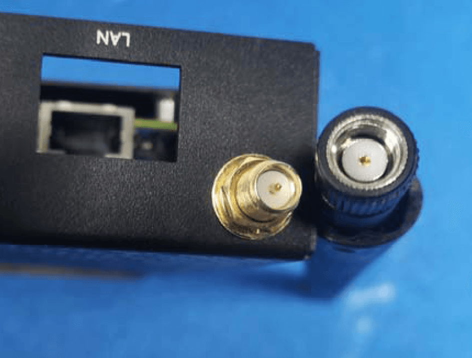
H79-023DS2
Jul 25, 2023NovoDS Digital Signage Solution
Equipment Class
DTS - Digital Transmission System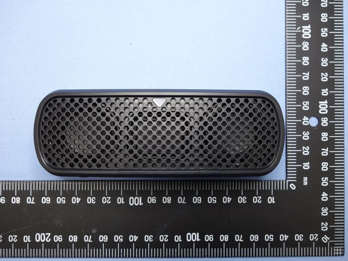
H79VFRU-25-46BT
Sep 27, 2022SIG Bluetooth speaker
Equipment Class
DSS - Part 15 Spread Spectrum Transmitter
H79-UNOC07X011
Nov 25, 2020UNOnext Indoor Air Quality Monitor
Equipment Class
DTS - Digital Transmission System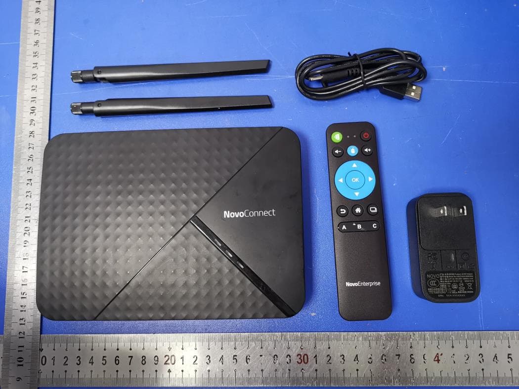
H79-019NC9
Jul 12, 2020NovoConnect Wireless Collaboration System
Equipment Class
NII - Unlicensed National Information Infrastructure TX