H8NBTM010Bluetooth Modem
Askey Computer Corp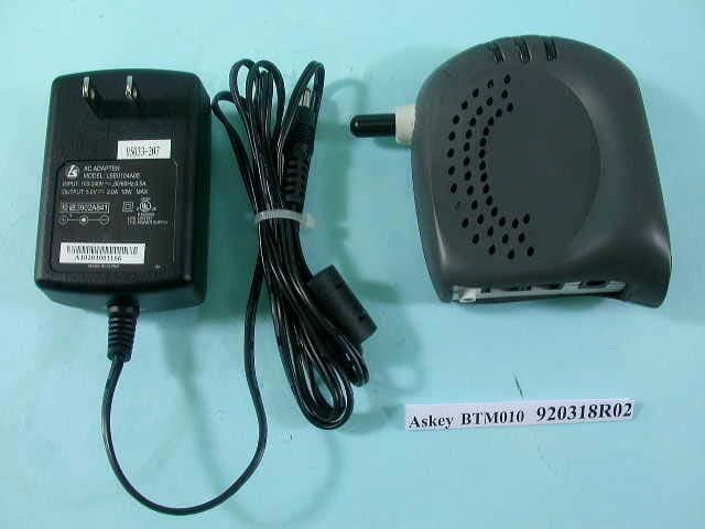
Click to zoom
Application Details
- Equipment Class
- DTS - Digital Transmission System
- Date of Grant
- Jun 02, 2003
- Application Purpose
- Original Equipment
- Date of Application
- Jun 02, 2003
- Equipment Note
- Bluetooth Modem
- Frequency Range
- 2402.00000000 - 2480.00000000
- Company
- Askey Computer Corp
- Country
- Taiwan
Documents & Files
Document Text
Text extracted from the exhibit documents filed with the FCC. Open a document above to read the original.
Users Manual
Bluetooth Modem User Manual 2003 All rights reserved. No part of this document may be reproduced or transmitted in any form or by any means, electronic or mechanical, for any purpose, without the express written permission of the seller. Disclaimer Information in this document is subject to change without notice. The material contained herein is supplied without representation or warranty of any kind. The seller therefore assumes no responsibility and shall have no liability of any kind arising from the supply or use of this document or the material contained herein. Trademarks All trademarks mentioned in this document are the property of their respective owners. March 19, 2003 Rev01 III Federal Communication Commission Interference Statement This equipment has been tested and found to comply with the limits for a Class B digital device, pursuant to Part 15 of the FCC Rules. These limits are designed to provide reasonable protection against harmful interference in a residential installation. This equipment generates, uses and can radiate radio frequency energy and, if not installed and used in accordance with the instructions, may cause harmful interference to radio communications. However, there is no guarantee that interference will not occur in a particular installation. If this equipment does cause harmful interference to radio or television reception, which can be determined by turning the equipment off and on, the user is encouraged to try to correct the interference by one of the following measures: - Reorient or relocate the receiving antenna. - Increase the separation between the equipment and receiver. - Connect the equipment into an outlet on a circuit different from that to which the receiver is connected. - Consult the dealer or an experienced radio/TV technician for help. This device complies with Part 15 of the FCC Rules. Operation is subject to the following two conditions: (1) This device may not cause harmful interference, and (2) this device must accept any interference received, including interference that may cause undesired operation. FCC Caution: Any changes or modifications not expressly approved by the party responsible for compliance could void the user's authority to operate this equipment . IMPORTANT NOTE: FCC Radiation Exposure Statement: This equipment complies with FCC radiation exposure limits set forth for an uncontrolled environment. This equipment should be installed and operated with minimum distance 20cm between the radiator & your body. This transmitter must not be co-located or operating in conjunction with any other antenna or transmitter. v Contents 1 Introduction ..................................................7 1.1 Overview........................................................................7 1.2 Features ........................................................................7 1.3 Package Contents .........................................................7 1.4 Minimum System Requirements ....................................8 2 Bluetooth Modem Installation.......................9 2.2 Rear Panel.....................................................................9 2.1 LED Indicators .............................................................10 3 Bluetooth USB Dongle Installation ............. 11 3.1 Software Installation .................................................... 11 4 Making Internet Connection .......................17 4.1 Connecting to the Internet...........................................17 4.2 Sharing Internet Connection ........................................18 Server Side ...............................................................18 Client Side.................................................................19 5 Removing Bluetooth Software....................21 6 Specification...............................................23 6.1 Bluetooth USB Dongle BT 210D..................................23 6.2 Bluetooth Modem 010 IC + V.90 ................................24 7 1 Introduction 1.1 Overview Thank you for choosing Bluetooth Modem. The Bluetooth Modem allows you to connect your personal computer to the Internet without cable. This is possible because it utilizes Bluetooth technology. Bluetooth is an open specification for short-range wireless networking standard and it is a low-cost wire-replacement technology that enables connectivity among a wide variety of electronic device such as computers, mobile phones, printers, laptops, PDAs and digital cameras. 1.2 Features • Plug-and-Play installation • Wireless connection with all Bluetooth Devices • Compliant with Bluetooth 1.1 • Supports File Transfer, Data Synchronization, Object Exchange, Network Access, Dial-up Networking, Serial Port Application • Supports up to 8 Bluetooth enable Devices 1.3 Package Contents Check the contents of the package against the pack contents checklist below. If any of the items is missing, contact the dealer from whom the equipment was purchased. • Bluetooth Modem • Bluetooth USB Dongle • Installation CD • Quick Installation Guide • Power Adapter and Cord Bluetooth Modem User Guide 8 1.4 Minimum System Requirements Before installation, please check that your computer complies with the following requirements: • CPU 166 MHz or higher • Minimum 16Mb RAM • Operating System: Windows 98, Me, 2000, XP • CD-ROM • USB port 9 2 Bluetooth Modem Installation Bluetooth Modem is extremely practical; it does not require installation software or driver. Just plug the AC Power cord in the Bluetooth Modem and it is ready for use. For safety, make sure the telephone line is UNPLUGGED from your modem. 2.2 Rear Panel 1. Plug one end of the RJ-11 phone cord into the LINE jack on the Bluetooth Modem, and plug the other end into your phone jack on the wall. 2. If you want to use a telephone on the Bluetooth Modem’s phone line while the modem is not used, plug the telephone’s cord into the modem’s PHONE jack. 3. Plug the AC adapter into the modem’s AC IN jack, and pl…
Text truncated - open the document above for the full version.
Cover Letter(s)
[email protected] www.adt.com.tw ADVANCE DATA TECHNOLOGY CORPORATION FEDERAL COMMUNICATIONS COMMISSION DECLARATION OF CONFORMITY (DoC) FOR THE FOLLOWING EQUIPMENT: PRODUCT NAME: BLUETOOTH MODEM (Receiver Part) MODEL NO.: BTM010 TRADE NAME: Askey IS HEREWITH CONFIRMED AND FOUND TO COMPLY WITH THE REQUIREMENTS OF CFR 47 PART 15 REGULATION. THE RESULTS OF ELECTROMAGNETIC EMISSION EVALUATION ARE SHOWN IN THE REPORT NO.: D920318R02 THIS DEVICE COMPLIES WITH PART 15 OF THE FCC RULES. OPERATION IS SUBJECT TO THE FOLLOWING TWO CONDITIONS: (1) THIS DEVICE MAY NOT CAUSE HARMFUL INTERFERENCE AND, (2) THIS DEVICE MUST ACCEPT ANY INTERFERENCE RECEIVED, INCLUDING INTERFERENCE THAT MAY CAUSE UNDESIRED OPERATION. THE FOLLOWING LOCAL MANUFACTURER/IMPORTER IS RESPONSIBLE FOR THIS DECLARATION: ManufacturerUSA Local Representative Company name: ASKEY COMPUTER CORP. To Be Determined. Address: 10F,NO.119, CHIENKANG RD., CHUNG- HO, TAIPEI TAIWAN R.O.C. Contact Person: John Chiou Title: Manager Tel/Fax: Tel: +886-2-2228-7588 Fax: +886-2-3234-9340
External Photos
Page 1 ANNEX PHOTOGRAPHS OF EUT Page 2
Internal Photos
Page 3 Page 4 Page 5 Page 6
Operational Description
FCC ID: H8NBTM010 ADT No.920318R02 Operational Description The transmitter of the EUT is powered by host equipment. The antenna is Dipole antenna with SMA antenna connector. Under normal use condition, the user has to keep at least 20cm separation distance between radiator and the body of the user. The other instruction, please have a look at the users manual. This device is a Frequency Hopping device with 79 hopping frequencies. The declared output power is only +10dBm.
RF Exposure Info
ADT No: 920318R02 1 FCC TEST REPORT REPORT NO.: RF920318R02 MODEL NO.: BTM010 ACCORDING: FCC Guidelines for Human Exposure IEEE C95.1 APPLICANT: ASKEY COMPUTER CORP. ADDRESS: 10F, 119, CHIENKANG RD., CHUNG-HO, TAIPEI, TAIWAN, 235, R.O.C. ISSUED BY: Advance Data Technology Corporation LAB LOCATION: 47 14th Lin, Chiapau Tsun, Linko, Taipei, Taiwan, R.O.C. 0528 ILAC MRA Lab Code: 200102-0 ADT No: 920318R02 2 RF Exposure Measurement 1. Introduction 2.4 GHz frequency band is regarded specially as a dangerous band for its heating harmfulness to the human body. That’s why microwave oven is operating in this frequency band. The manufacturer whose product is working in this frequency band is obligatory to prove the harmfulness of his product. In this document, we try to prove the safety of radiation harmfulness to the human body for our product. The limit for Maximum Permissible Exposure (MPE) specified in FCC 1.1310 is followed. The Gain of the antenna used in this product is measured in a Fully Anechoic Chamber (FAC) calibrated for antenna measurement in ADT, and also the maximum total power input to the antenna is measured. Through the Friis transmission formula and the maximum gain of the antenna, we can calculate the distance, away from the product, where the limit of MPE is reached. Although the Friis transmission formula is a far field assumption, the calculated result of that is an over-prediction for near field power density. We will take that as the worst case to specify the safety range. 2. RF Exposure Limit According to FCC 1.1310: The criteria listed in the following table shall be used to evaluate the environmental impact of human exposure to radio-frequency (RF) radiation as specified in 1.1307(b) LIMITS FOR MAXIMUM PERMISSIBLE EXPOSURE (MPE) Frequency Range (MHz) Electric Field Strength (V/m) Magnetic Field Strength (A/m) Power Density (mW/cm 2 ) Average Time (minutes) (A)Limits For Occupational / Control Exposures 300-1500......F/3006 1500-100,000......56 (B)Limits For General Population / Uncontrolled Exposure 300-1500......F/15006 1500-100,000......1.030 F = Frequency in MHz ADT No: 920318R02 3 3. Friis Formula Friis transmission formula : Pd = (Pout*G) / (4*pi*r 2 ) where Pd = power density in mW/cm 2 Pout = output power to antenna in mW G = gain of antenna in linear scale Pi = 3.1416 R = distance between observation point and center of the radiator in cm Pd is the limit of MPE, 1 mW/cm 2 . If we know the maximum Gain of the antenna and the total power input to the antenna, through the calculation, we will know the distance r where the MPE limit is reached. Ref. : David K. Cheng, Field and Wave Electromagnetics, Second Edition, Page 640, Eq. (11-133). 4 EUT Operating condition The software provided by Manufacturer enabled the EUT to transmit and receive data at lowest, middle and highest channel individually. 5 Climate Condition The temperature and related humidity: 20 deg. C and 50 % RH 6. Classification This device is not fixed inside the host equipment, it is connected with host through wire. So it is easy to be re-located in the place where at least 20 cm far away from the body of the user. Warning statement to the user for keeping at least 20cm or more separation distance with the antenna should be included in users manual. So, this device is classified as Mobile Device. ADT No: 920318R02 4 7 Test Results 7.1 Antenna Gain The maximum Gain measured in Fully Anechoic Chamber is 1dBi or 1.258 (numeric). 7.2 Output Power Into Antenna & RF Exposure Distance : CHANNEL CHANNEL FREQUENCY (MHz) OUTPUT POWER TO ANTENNA (mW) MINIMUM ALLOWABLE DISTANCE ( r ) FROM SKIN (Centi-Meter) 024022.560.51 3924412.050.45 7824801.580.40 The minimum allowable distance is very close to the enclosure of the antenna. So, the user has no need to worry about the harmfulness of radiation. But it is recommended to always keep, at least, 20cm separation distance with the antenna.
Test Report
FCC ID: H8NBTM010 Report No.: RF920318R02 1 Issued: April 19, 2003 FCC TEST REPORT REPORT NO.: RF920318R02 MODEL NO.: BTM010 RECEIVED: Mar. 18, 2003 TESTED: Mar. 21 ~ Mar. 27, 2003 APPLICANT: ASKEY COMPUTER CORP. ADDRESS: 10F, 119, CHIENKANG RD., CHUNG-HO, TAIPEI, TAIWAN, 235, R.O.C. ISSUED BY: Advance Data Technology Corporation LAB LOCATION: 47 14th Lin, Chiapau Tsun, Linko, Taipei, Taiwan, R.O.C. This test report consists of 66 pages in total. It may be duplicated completely for legal use with the approval of the applicant. It should not be reproduced except in full, without the written approval of our laboratory. The client should not use it to claim product endorsement by CNLA, NVLAP or any government agencies. The test results in the report only apply to the tested sample. 0528 ILAC MRA Lab Code: 200102-0 FCC ID: H8NBTM010 Report No.: RF920318R02 2 Issued: April 19, 2003 TABLE OF CONTENTS 1CERTIFICATION .........................................................................................................................4 2SUMMARY OF TEST RESULTS.................................................................................................5 3GENERAL INFORMATION .........................................................................................................6 3.1GENERAL DESCRIPTION OF EUT............................................................................. 6 3.2DESCRIPTION OF TEST MODES............................................................................... 7 3.3GENERAL DESCRIPTION OF APPLIED STANDARDS.............................................. 7 3.4DESCRIPTION OF SUPPORT UNITS ......................................................................... 8 4TEST PROCEDURES AND RESULTS .......................................................................................9 4.1CONDUCTED EMISSION MEASUREMENT ............................................................... 9 4.1.1LIMITS OF CONDUCTED EMISSION MEASUREMENT ...........................................................9 4.1.2TEST INSTRUMENTS ................................................................................................................9 4.1.3TEST PROCEDURES ...............................................................................................................10 4.1.4DEVIATION FROM TEST STANDARD.....................................................................................10 4.1.5TEST SETUP ............................................................................................................................11 4.1.6EUT OPERATING CONDITIONS..............................................................................................11 4.1.7TEST RESULTS ........................................................................................................................12 4.2NUMBER OF HOPPING FREQUENCY USED .......................................................... 18 4.2.1LIMIT OF HOPPING FREQUENCY USED ...............................................................................18 4.2.2TEST INSTRUMENTS ..............................................................................................................18 4.2.3TEST PROCEDURES ...............................................................................................................19 4.2.4DEVIATION FROM TEST STANDARD.....................................................................................19 4.2.5TEST SETUP ............................................................................................................................20 4.2.6TEST RESULTS ........................................................................................................................20 4.3DWELL TIME ON EACH CHANNEL .......................................................................... 23 4.3.1LIMIT OF DWELL TIME USED .................................................................................................23 4.3.2TEST INSTRUMENTS ..............................................................................................................23 4.3.3TEST PROCEDURES ...............................................................................................................24 4.3.4DEVIATION FROM TEST STANDARD.....................................................................................24 4.3.5TEST SETUP ............................................................................................................................24 4.3.6TEST RESULTS ........................................................................................................................25 4.4CHANNEL BANDWIDTH............................................................................................ 32 4.4.1LIMITS OF CHANNEL BANDWIDTH........................................................................................32 4.4.2TEST INSTRUMENTS ..............................................................................................................32 4.4.3TEST PROCEDURE .................................................................................................................33 4.4.4DEVIATION FROM TEST STANDARD.....................................................................................33 4.4.5TEST SETUP ............................................................................................................................33 4.4.6EUT OPERATING CONDITION ................................................................................................33 4.4.7TEST RESULTS ........................................................................................................................34 4.5HOPPING CHANNEL SEPARATION ......................................................................... 38 4.5.1LIMIT OF HOPPING CHANNEL SEPARATION........................................................................38 FCC ID: H8NBTM010 Report No.: RF920318R02 3 Issued: April 19, 2003 4.5.2TEST INSTRUMENT…
Text truncated - open the document above for the full version.
Test Report
FCC ID: H8NBTM010 Report No.: RF920318R02 44 Issued: April 19, 2003 4.6 MAXIMUM PEAK OUTPUT POWER –USING SPECTRUM ANALYZER 4.6.1 LIMITS OF MAXIMUM PEAK OUTPUT POWER MEASUREMENT The Limit of Maximum Peak Output Power Measurement is 30dBm. 4.6.2 INSTRUMENTS Description & ManufacturerModel No.Serial No.Calibrated Until SPECTRUM ANALYZER FSEK30100049July 24, 2003 NOTE: The calibration interval of the above test instruments is 12 months and the calibrations are traceable to NML/ROC and NIST/USA. FCC ID: H8NBTM010 Report No.: RF920318R02 45 Issued: April 19, 2003 4.6.3 TEST PROCEDURES 1. Check the calibration of the measuring instrument using either an internal calibrator or a known signal from an external generator. 2. Turn on the EUT and connect it to measurement instrument. Then set it to any one convenient frequency within its operating range. Set a reference level on the measuring instrument equal to the highest peak value. 3. The center frequency of the spectrum analyzer is set to the fundamental frequency and using 3 MHz RBW and 3 MHz VBW. 4. Measure the frequency difference of two frequencies that were attenuated 20dB from the reference level. Record the frequency difference as the emission bandwidth. 5. Repeat above procedures until all frequencies measured were complete. 4.6.4 DEVIATION FROM TEST STANDARD No deviation FCC ID: H8NBTM010 Report No.: RF920318R02 46 Issued: April 19, 2003 4.6.5 TEST SETUP For the actual test configuration, please refer to the related Item – Photographs of the Test Configuration. 4.6.6 EUT OPERATING CONDITION The software provided by client enabled the EUT to transmit and receive data at lowest, middle and highest channel frequencies individually. EUT SPECTRUM ANALYZER FCC ID: H8NBTM010 Report No.: RF920318R02 47 Issued: April 19, 2003 4.6.7 TEST RESULTS Output Power to Antenna: CHANNEL CHANNEL FREQUENCY (MHz) PEAK POWER OUTPUT (dBm) PEAK POWER LIMIT (dBm) PASS/FAIL 024024.0830PASS 3924413.1130PASS 7824801.9830PASS FCC ID: H8NBTM010 Report No.: RF920318R02 48 Issued: April 19, 2003 Channel 0 FCC ID: H8NBTM010 Report No.: RF920318R02 49 Issued: April 19, 2003 Channel 39 FCC ID: H8NBTM010 Report No.: RF920318R02 50 Issued: April 19, 2003 Channel 78 FCC ID: H8NBTM010 Report No.: RF920318R02 51 Issued: April 19, 2003 4.7 RADIATED EMISSION MEASUREMENT 4.7.1 LIMITS OF RADIATED EMISSION MEASUREMENT Emissions radiated outside of the specified bands, shall be according to the general radiated limits in 15.209 as following: Frequencies (MHz) Field strength (microvolts/meter) Measurement distance (meters) 0.009-0.4902400/F(kHz)300 0.490-1.70524000/F(kHz)30 1.705-30.03030 30-881003 88-2161503 216-9602003 Above 9605003 As shown in 15.35(b), for frequencies above 1000MHz, the field strength limits are based on average detector, however, the peak field strength of any emission shall not exceed the maximum permitted average limits, specified above by more than 20dB under any condition of modulation. FCC ID: H8NBTM010 Report No.: RF920318R02 52 Issued: April 19, 2003 4.7.2 TEST INSTRUMENTS DESCRIPTION & MANUFACTURERMODEL NO.SERIAL NO.CALIBRATED UNTIL * HP Spectrum Analyzer8590L3544A01176May 13, 2003 * HP Preamplifier8447D2944A08485Apr. 29, 2003 * HP Preamplifier8449B3008A01201Dec. 01, 2003 * HP Preamplifier8449B3008A01292Aug. 07, 2003 *Spectrum Analyzer8593E3926A04191Mar. 24, 2004 *Test ReceiverESI7838496/016Feb. 23, 2004 SCHAFFNER Tunable Dipole Antenna SCHWARZBECK Tunable Dipole Antenna VHBA 9123 UHA 9105 459 977 Nov. 22, 2003 * CHASE BILOG AntennaCBL6112A2221Aug. 02, 2003 * SCHWARZBECK Horn Antenna BBHA9120-D1D130July 03, 2003 * EMCO Horn Antenna31159312-4192Apr. 09, 2003 * EMCO Turn Table10601115NA * SHOSHIN TowerAP-4701A6Y005NA * Software ADT_Radiated _V5.09 NANA * ANRITSU RF SwitchesMP59BM35046Jul. 11. 2003 * TIMES RF cableLMR-600CABLE-ST5-01Jul. 11. 2003 NOTE:1. The calibration interval of the above test instruments is 12 months. And the calibrations are traceable to NML/ROC and NIST/USA. 2. “*” = These equipment are used for the final measurement. 3. The horn antenna and HP preamplifier (model: 8449B) are used only for the measurement of emission frequency above 1GHz if tested. 4. The test was performed in ADT Open Site No. 5. 5. The VCCI Site Registration No. is R-1039. FCC ID: H8NBTM010 Report No.: RF920318R02 53 Issued: April 19, 2003 4.7.3 TEST PROCEDURES a. The EUT was placed on the top of a rotating table 0.8 meters above the ground at a 10 meter open area test site. The table was rotated 360 degrees to determine the position of the highest radiation. b. The EUT was set 3 meters away from the interference-receiving antenna, which was mounted on the top of a variable-height antenna tower. c. The antenna is a broadband antenna, and its height is varied from one meter to four meters above the ground to determine the maximum value of the field strength. Both horizontal and vertical polarizations of the antenna are set to make the measurement. d. For each suspected emission, the EUT was arranged to its worst case and then the antenna was tuned to heights from 1 meter to 4 meters and the rotatable table was turned from 0 degrees to 360 degrees to find the maximum reading. e. The test-receiver system was set to Peak Detect Function and Specified Bandwidth with Maximum Hold Mode. f. If the emission level of the EUT in peak mode was 10 dB lower than the limit specified, then testing could be stopped and the peak values of the EUT would be reported. Otherwise the emissions that did not have 10 dB margin would be re- tested one by one using peak, quasi-peak or average method as specified and then reported in a data sheet. NOTE: 1. The resolution bandwidth and video bandwidth of test receiver/spectrum analyzer is 120kHz for Peak detection (PK) and Quasi-peak detection (QP) at frequency below 1GHz. 2. The resolution bandwidth and video bandwidth of test receiver/spectrum analyzer is 1 MHz for Peak detection at frequency above 1GHz. 3. The resolution bandwidth of test rec…
Text truncated - open the document above for the full version.
Test Setup Photos
FCC ID: H8NBTM010 Report No.: RF920318R02 64 Issued: April 19, 2003 5 PHOTOGRAPHS OF THE TEST CONFIGURATION CONDUCTED EMISSION TEST FCC ID: H8NBTM010 Report No.: RF920318R02 65 Issued: April 19, 2003 RADIATED EMISSION TEST
Contact Information
Applicant
Jack Po(Manager)
Technical Contact
Advance Data Technology CorporationEllis Wu
[email protected]+886 3 327 0910
13-1, Lane 19, WenShan 3rd St · Taoyuan · Taiwan
Test Firm
Bureau Veritas CPS (H.K.) Ltd. Taoyuan BranchRichard Chen
Technical Specifications
| # | Rule Parts | Frequency Range | Power Output |
|---|---|---|---|
| 1 | 15C | 2.40 GHz - 2.48 GHz | 3.00 mW |
Other Applications from Askey Computer Corp
H8N-NUQ2006
Sep 11, 2026enterprise-grade 5G NR outdoor unit
Equipment Class
CBD - Citizens Band Category A and B DevicesH8NSCU5000
Jun 18, 20265G Small cell
Equipment Class
CBD - Citizens Band Category A and B DevicesH8N-EAI2620P
Jan 29, 2026Indoor Wi-Fi 7 Enterprise Access Point
Equipment Class
DTS - Digital Transmission SystemH8N-CTX0800
Oct 07, 2024OBU
Equipment Class
NII - Unlicensed National Information Infrastructure TX
H8NEAO2522P-2
Jul 04, 2024Outdoor WiFi6 AP
Equipment Class
DTS - Digital Transmission System