H8NHNH010D75Home Lan Modem
Askey Computer Corp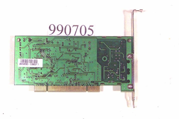
Click to zoom
Application Details
- Equipment Class
- JBP - Part 15 Class B Computing Device Peripheral
- Date of Grant
- Dec 15, 1999
- Application Purpose
- Original Equipment
- Date of Application
- Sep 18, 1999
- Equipment Note
- Home Lan Modem
- Company
- Askey Computer Corp
- Country
- Taiwan
Documents & Files
Document Text
Text extracted from the exhibit documents filed with the FCC. Open a document above to read the original.
Users Manual
1 Home-LAN Manual TABLE 1 INTRODUCTION ................................................................................................................................ 1 1.1 Package Includes ......................................................................................................................... 2 1.2 Minimum System Requirements ................................................................................................... 2 2 HARDWARE INSTALLATION.........................................................................................................3 2.1 Home-LAN Installation................................................................................................................ 3 2.2 Connection Diagram ................................................................................................................... 3 3 DRIVER INSTALLATION ................................................................................................................. 5 3.1 Driver Installation for Windows 95 ............................................................................................. 5 3.2 Driver Installation for Windows 98 ............................................................................................. 9 4 WINGATE™ INSTALLATION ....................................................................................................... 15 4.1 WinGate™ Installation for “Gateway/ Server” ........................................................................ 15 4.2 WinGate™ Installation for “Client” .........................................................................................17 1 INTRODUCTION Home-LAN allows users not only to share local disks and printers over the network, but also to share a single Internet account simultaneous. The computer (configured as Gateway/Server) can share Internet account with the other networked computers. With Home-LAN, Networking is no longer expensive and complex. Ease and convenience Home-LAN networking use existing telephone wiring as medium for networking PCs. There are no complicated network wiring and administration. With easy networking configuration and ordinary phone wiring, you can network your PC from most any where at home. The provided software handles the complex communications that make traditional networks so hard. Cost savings Home-LAN provides total package of home networking. Give everyone access the networked PCs’ sources, such as printers, Internet access simultaneous, files and more. 2 1.1 Package Includes • A Home-LAN PCI Card • A Phone Cord • An Quick Installation • A CD-Based Software, including drivers for Windows 95 ® /98 ® ,WinGate™ Software, Installation Guide 1.2 Minimum System Requirements • PC with at least a 586 microprocessor (Pentium ® recommended) • At least 16MB RAM • At least 8 MB available hard drive space • Microsoft ® Windows ® 95/98 Operating System • Available PCI slot • CD-ROM drive • For Internet sharing, at least one PC (configured as the Server/Gateway) must have a modem and a valid Internet account. • You may need Windows 95/98 CD handy (containing the version of Windows currently running on your PC ) because Windows 95/98 may ask for Windows 95/98 CD to copy network components during software installation process. • You may need phone cords for connecting depending on your network configuration. 3 2 HARDWARE INSTALLATION SAFETY PRECAUTION: Turn off your electronic devices, including your personal computer, before you begin to connect and disconnect cables. 2.1 Home-LAN Installation Follow the steps below to install Home-LAN card(s) into your PC(s). Step 1: With the power to your PC disconnected, remove the PC's casing. Step 2: Press the Home-LAN card firmly into the PCI slot, and secure it with screws to your PC. Step 3: Reinstall the casing on your PC. 2.2 Connection Diagram After installing the Home-LAN cards into your PC, you need to connect your network and related devices. For connecting, you just need: • Attach the phone cord to the port marked “network” on your Home-LAN card and a nearby phone jack. • For adding another PC to your Home-LAN network, connect two Home-LANs with phone cord. The typical Home Network Connection with Home-LAN network solution is illustrated in Diagram 2-1. We suppose the Server/Gateway PC and Client 1& 2 PCs are located in different rooms in the home. The three PCs are networked together to share each other over the existing phoneline and Home-LANs. Diagram 2-1 4 The left side of the diagram above describes a Home Computer used as a Server/Gateway. A Server/Gateway is defined as a system that has an ISP account setup and has a communication device like a modem installed on it for connection to Internet. The Server/Gateway system is connected to a nearby phone jack. The right side of the diagram describes two clients daisy chained together (multiple connection) with the Home-LAN card. A Client is defined as a computer that gets Internet access through the Server/Gateway. Client 1 is connected to a nearby phone jack. It is recommended to install and configure the Home-LAN card on Server/Gateway first. There must be only one PC configured as Server/Gateway on your Home-LAN network. 5 3 DRIVER INSTALLATION After install Home-LAN into your PC, you need to install the driver first; then install WinGate software. This chapter describes the driver installation for your Home-LAN. 3.1 Driver Installation for Windows 95 1. After installing Home-LAN into your PC, power on your PC. 2. Start Windows 95 with provided CD in your CD-ROM drive. The “Update Hardware Wizard” appears announcing the detecting of “PCI Ethernet Controller”. Click “Next”. 3. Windows 95 will find and install the appropriate drivers. Click “ Finish “. Then Windows will copy necessary files into your hard disk. Note: If Windows can not locate the drivers for your new hardware, please click “Other locations...” to locate your CD-ROM drive. 6 4. When prompted with the mess…
Text truncated - open the document above for the full version.
Users Manual
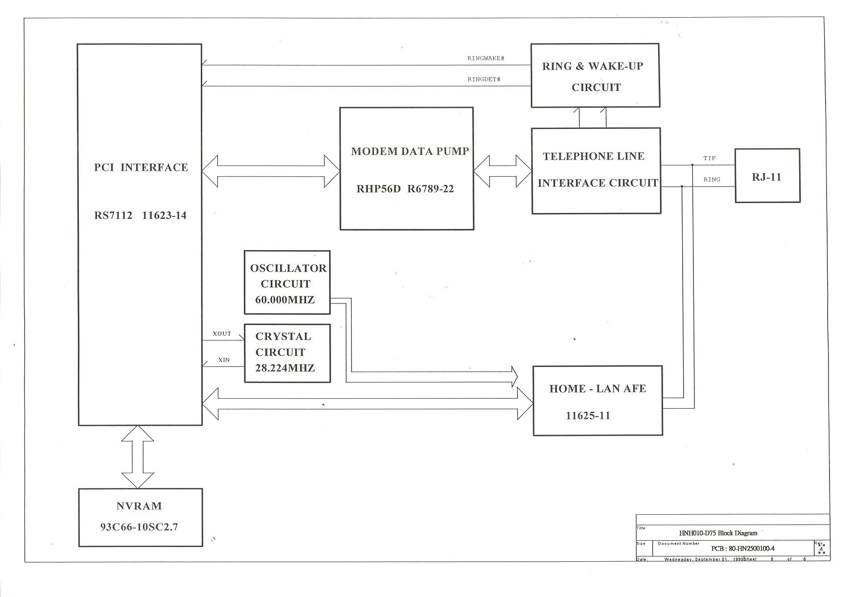
ASKEY COMPUTER CORP. SUBJECT : Product Specification MODEL : HNH010-D75 REV : 02 RL DATE : AUG-11-1999 PAGES: 6 CONTENTS : Prepared By : Reviewed By : Approval By : TABLE OF CONTENTS Introduction Product Specification Function Requirement - Home LAN Communication - Data Communication - Fax communication - Diagnostics Capabilities - Modem Operational Characteristics - Operating System - Compatibility Requirement - Customer Requirements Interface Specification - DTE Interface - Telephone Network Interface - Power Management Interface Product Reliability Operating Environment Mechanical Characteristics - Dimensions - Flammability Regulatory Standard Compliance Introduction The specification defines the product requirement for the HNH010-D75 modem module. The modem is a Home LAN + Controller-less design using Conexant RS7112/RHP56LD chipset for PCI interface that provides HomePNA, Data and Fax communication features described as following: Product Specification Function Requirement - Home LAN Communication * Protocols : HomePNA 1.0 Specification * Data Speed : 1Mbps data rate * AFE type: Integrated AFE - Data Communication * Protocols : V.90, V.34, V.32bis, V.32, V.23, V.22bis, V.22, V.21, Bell212A and Bell103 * Error Correction : V.42, MNP2-4 * Data Compression : V.42bis, MNP5 * Command set : Enhanced TIA/EIA-602 command set * DTE Speed : 300 to 115200 bps * Data Format : 10 bits, including start bit, stop bit and parity - Fax Communication * Protocols : V.17, V.29, V.27ter, V.21 ch 2 * Fax type : Group 3 compatible * Command set : TIA/EIA-578 class 1 Fax command set - Diagnostics Capabilities * Analog loopback and analog loopback selftest * Remote digital loopback and remote digital loopback selftest - Modem operational Characteristics Under FCC Spec. * Transmit Level : less than -11 dbm +/- 2 dBm W/O AGC * Receive sensitivity : -35 dBm +/- 2 dBm Under V.34 mode * Guard Tone : 550 or 1800 Hz +/- 20 Hz * Answer Tone : CCITT 2100 Hz +/- 15 Hz * Bell 2225 Hz +/- 10 Hz * Dialing Method Under FCC: 1) Tone dialing (A) Symbols : 1 2 3 4 5 6 7 8 9 0 # * A B C D (B) Frequency : within +/- 1.5% (C) High Group Level : -6 dBm +/- 2 dBm (D) Low Group Level : -8 dBm +/- 2 dBm 2) Pulse dialing (A) Duration : 10 pps +/- 2 pps (B) M/B ration : 39 +/- 10% or 33 +/- 10% * Call Progress Tone Detection : 340Hz ~ 640 Hz @ 0 dBm ~ -38 dBm * Ring detection : 15Hz~68Hz, 30Vrms~150 Vrms, 1~3 sec ON/3~5 sec OFF * Modem bit error rates : error less than 10E-5 at nominal SNR * Power consumption : 1) Sleep mode : 50mW @ +5VDC +/- 5% 2) Idle mode : 500mW @ +5VDC +/- 5 % 3) Connection mode : 800mW @ +5VDC +/- 10 % - Operating Systems * Windows 2K * Windows 95 & OSR2 * Windows 98 * Windows NT 4.0 * Windows NT 5.0 - Compatibility Requirements The modem must reliably connect to popular data modems and fax machines. - Customer requirements * Auto dial and auto answer * ACPI power management * User selectable country setting through driver Interface Specification - DTE interface The modem provides PCI bus as following definition. *PCI SIG Specification 2.2 *PCI SIG Specification 2.1 *Meets PC99 Requirements *5V and VAUX power Auto switch - Telephone Network Interface The RJ-11C type telephone jack. - Power Management Interface *ACPI power management meets PC99 *PCI SIG Power Management Specification 1.1A *D3 cold function supports *Supports PME signal to wake up the system when Receives ring signal. Product Reliability The calculated MTBF shall be greater than 50000 hours. The calculation shall be made under following assumptions : Ambient Temperature : 40 degree C, inlet air temperature Operating Environment * Operating temperature : 0 to 50 degree C * Shipping and storage temperature : -40 to 65 degree C * Operating Humidity : 8% to 80% none-condensing * Altitude : 0 to 10000 feet Mechanical Characteristics - Dimensions The modem assembly consists of one 2 layer PCB assembly. The modem is approximately 68.5mm x 145mm. - Assembly The polymeric materials used in the modem assembly meet of exceed the requirement of UL 94. Regulatory standards compliance The product must compliance with all the following regulatory standards : * UL1950 3rd Edition * CSA * DOC * FCC part 15 and FCC part 68 * JATE
External Photos
FCC ID : H8NHNH010D75Front of Side EUT Number 1 990705-1.JPG FCC ID : H8NHNH010D75Rear of Side EUT Number 2 990705-2.JPG FCC ID : H8NHNH010D75Rear of Side EUT Number 3 990705-4.jpg FCC ID : H8NHNH010D75Front of Side EUT Number 4 990705-3f1.JPG
ID Label/Location Info
EXHIBIT A. FCC ID LABEL FCC ID:H8NHNH010D75 The next page shows the location of FCC ID on EUT. The following statement will be placed in the User’s Manual. This device complies with Part 15 of the FCC Rules. Operation is subject to the following two conditions :(1) this device may not cause harmful interference, and (2) this device must accept any interference received, including interference that may cause undesired operation.
Contact Information
Applicant
Jack Po(Manager)
Technical Contact
SPORTON International Inc.Kathy Lin
[email protected]886-2-26962468
6F, No. 106, Sec. 1, Hsin Tai Wu Rd., Hsi Chin, · Taipei Hsien · Taiwan
Non-Technical Contact
SPORTON International Inc.Kathy Lin
[email protected]718-468-4260
Test Firm
Sporton International Inc.W. Huang
Technical Specifications
| # | Rule Parts | Frequency Range | Power Output |
|---|---|---|---|
| 1 | 15B | - | - |
Other Applications from Askey Computer Corp
H8N-NUQ2006
Sep 11, 2026enterprise-grade 5G NR outdoor unit
Equipment Class
CBD - Citizens Band Category A and B DevicesH8NSCU5000
Jun 18, 20265G Small cell
Equipment Class
CBD - Citizens Band Category A and B DevicesH8N-EAI2620P
Jan 29, 2026Indoor Wi-Fi 7 Enterprise Access Point
Equipment Class
DTS - Digital Transmission SystemH8N-CTX0800
Oct 07, 2024OBU
Equipment Class
NII - Unlicensed National Information Infrastructure TX
H8NEAO2522P-2
Jul 04, 2024Outdoor WiFi6 AP
Equipment Class
DTS - Digital Transmission System