H8NPCICARD54PCI Wireless LAN Card
Askey Computer Corp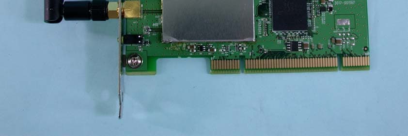
Click to zoom
Application Details
- Equipment Class
- DTS - Digital Transmission System
- Date of Grant
- Mar 04, 2004
- Application Purpose
- Original Equipment
- Date of Application
- Mar 04, 2004
- Equipment Note
- PCI Wireless LAN Card
- Frequency Range
- 2412.00000000 - 2462.00000000
- Company
- Askey Computer Corp
- Country
- Taiwan
Documents & Files
Document Text
Text extracted from the exhibit documents filed with the FCC. Open a document above to read the original.
Users Manual
Be inspired s Issued by Information and Communication mobile Haidenauplatz 1 D-81667 Munich © Siemens AG 2003 All rights reserved. Subject to availability. Rights of modification reserved. 06/2003 Siemens Aktiengesellschaft http://www.my-siemens.com No.: A31008-E505-B102-1-PED1 Gigaset PCI Card Wireless LAN Kurzbedienungsanleitung Quick Installation Guide Guide d’installation rapide Guida rapida Beknopte gebruikershandleiding Guía de manejo rápida Snabbguide Kort brugsanvisning Pikaohje Hurtigguide Guia para uma instalação rápida 54 BA PCI card 54 +.qxd 26.06.2003 11:25 Uhr Seite 1 1 Table of Contents Gigaset PCI Card 54 / -- / A31008-E505-B102-1-PED1 / PCIcard_qigIVZ.fm / 03.07.2003 deutsch english français italiano nederlands español suomi dansk svenska norsk portugués Table of Contents Kurzbedienungsanleitung 3 Quick Installation Guide 11 Guide d'installation rapide19 Guida rapida 27 Beknopte gebruikershandleiding 35 Guía de manejo rápida43 Snabbguide51 Kort brugsanvisning59 Pikaohje 67 Hurtigguide 75 Guia para uma instalação rápida 83 2 Table of Contents Gigaset PCI Card 54 / -- / A31008-E505-B102-1-PED1 / PCIcard_qigIVZ.fm / 03.07.2003 3 Kurzbedienungsanleitung Gigaset PCI Card 54 / -- / A31008-E505-B102-1-PED1 / shortref_pci_de.fm / 03.07.2003 deutsch english français italiano nederlands español suomi dansk svenska norsk portugués Kurzbedienungsanleitung Diese Kurzbedienungsanleitung zeigt Ihnen, wie Sie die Gigaset PCI Card 54 an Ihren PC anschließen und eine Verbindung zu einem Access Point herstellen. Detaillierte Infor- mationen finden Sie in der Bedienungsanleitung in elektronischer Form auf der mitge- lieferten CD und im Internet unter www.my-siemens.com/pcicard54 . Warenzeichen Microsoft, Windows 98, Windows 98 SE, Windows ME, Windows 2000 und Windows XP und Internet Explorer sind registrierte Warenzeichen der Microsoft Corporation. Netscape, Netscape Navigator und Netscape Communicator sind registrierte Warenzei- chen der Netscape Communications Corporation. Sicherheitshinweise ◆Schützen Sie das Gerät vor Feuchtigkeit. ◆Die Gigaset PCI Card 54 kann den Betrieb von medizinischen Geräten beeinflussen. Beachten Sie daher die technischen Bedingungen der entsprechenden Umgebung. ◆Händigen Sie die Bedienungsanleitung mit aus, wenn Sie Ihre Gigaset PCI Card 54 an eine andere Person weitergeben. ◆Entsorgen Sie die Gigaset PCI Card 54 umweltgerecht. Hinweise zum sicheren Betrieb Sobald Sie alle Arbeitsschritte dieser Kurzbedienungsanleitung durchgeführt und eine Verbindung zum Access Point hergestellt haben, sollten Sie Sicherheitseinstellungen am kabellosen Netzwerk vornehmen: ◆die SSID für alle kabellosen Geräte Ihres Netzwerks ändern ◆einen Verschlüsselungsmechanismus (WEP-Verschlüsselung) verwenden Packungsinhalt Die Verpackung enthält die folgenden Bestandteile: ◆die Gigaset PCI Card 54 ◆eine Antenne ◆eine Installations-CD einschließlich Bedienungsanleitung und dem Dokument „Prak- tische Anwendungsfälle und Konfigurationsbeispiele“ ◆diese Kurzbedienungsanleitung Systemanforderungen Zum Betrieb benötigen Sie: ◆einen PC mit einem der folgenden Betriebssysteme: Windows 98, Windows 98 SE, Windows ME, Windows 2000 oder Windows XP ◆64 MB RAM, mehr Speicher ist empfehlenswert ◆mindestens 30 MB Festplattenkapazität ◆einen freien PCI-Steckplatz 4 Kurzbedienungsanleitung Gigaset PCI Card 54 / -- / A31008-E505-B102-1-PED1 / shortref_pci_de.fm / 03.07.2003 Überblick über die Installationsschritte eines Netzwerks Um ein kabelloses Netzwerk (Ad-hoc-Netzwerk) aufzubauen, benötigen Sie für jeden PC, der an das Netz angeschlossen werden soll, einen kabellosen Netzwerkadapter, zum Beispiel die Gigaset PCI Card 54 oder die Gigaset PC Card 54. Um ein Netzwerk mit kabellosen und kabelgebundenen Komponenten (Infrastruktur- Netzwerk) und mit Internet-Zugang aufzubauen, benötigen Sie zusätzlich einen Access Point, zum Beispiel den kabellosen Router Siemens Gigaset SE 505 dsl/cable. Um das Netzwerk im Infrastruktur-Modus aufzubauen, gehen Sie wie folgt vor: 1. Bauen Sie zunächst die Gigaset PCI Card 54 in einen PC ein. Dies ist auf S. 5 beschrie- ben. 2. Installieren Sie die Software. Der Installationsvorgang ist im Folgenden für die Be- triebssysteme Windows 98, 98 SE, ME und 2000 auf S. 6 und für Windows XP auf S. 7 beschrieben. 3. Installieren Sie dann den Access Point. Dies ist in der Bedienungsanleitung des ent- sprechenden Gerätes beschrieben. 4. Stellen Sie dann die Verbindung von der Gigaset PCI Card 54 zum Access Point her. Dies ist auf S. 8 beschrieben. 5. Optional können Sie weitere PCs kabellos anschließen. i Beachten Sie bitte bei der Installation der Gigaset PCI Card 54, dass die SSID (Service Set ID) aller kabellosen Netzwerkkomponenten identisch sein muss. Die voreingestellte SSID aller Gigaset-Produkte für kabellose Netzwerke ist ConnectionPoint. 5 Kurzbedienungsanleitung Gigaset PCI Card 54 / -- / A31008-E505-B102-1-PED1 / shortref_pci_de.fm / 03.07.2003 deutsch english français italiano nederlands español suomi dansk svenska norsk portugués Einbau der Gigaset PCI Card 54 Beachten Sie beim Einbau der Gigaset PCI Card 54 in Ihren PC unbedingt die folgenden Sicherheitshinweise: Gehen Sie wie folgt vor: 1. Schalten Sie Ihren PC aus und ziehen Sie den Netzstecker. 2. Öffnen sie das Gehäuse Ihres PCs, setzen Sie die Gigaset PCI Card 54 ein und schlie- ßen Sie das Gehäuse wieder. 3. Befestigen Sie die mitgelieferte Antenne an der Gigaset PCI Card 54. 4. Starten Sie Ihren PC, damit Sie mit der Installation der Software beginnen können. 5. Beim Hochfahren meldet sich der Hardware-Assistent. Klicken Sie auf Abbrechen und beginnen Sie mit der Installation (siehe nächster Abschnitt). ! – Ziehen Sie nach dem Ausschalten des PCs auch den Netzstecker. – Beachten Sie, dass einige Bauteile Ihres PCs auch bei gezogenem Netzstecker noch Spannung führen könnten. – Vermeiden Sie die Berührung elektrischer und elektronischer Bauteile, und halten Sie die Gigaset PCI Card 54 nur am Blechwinkel oder am äußer…
Text truncated - open the document above for the full version.
External Photos
Page 1 CONSTRUCTION PHOTOS OF EUT Page 2
ID Label/Location Info
Label Location
ID Label/Location Info
~3071497.jpg (2467 x 3499 x 24)
Internal Photos
Page 3
Operational Description
FCC ID: H8NPCICARD54 Report No.920828R01B Operational Description This device is a PCI Wireless LAN Card which operates in 2.4GHz band, the maximum data rate could be up to 54Mbps which OFDM technique will be applied. If the signal to noise radio is too poor which could not support 54Mbps, the 11Mbps data rate with CCK technique will be applied. The transmitter of the EUT is powered by host equipment via a PCI interface. The antenna is Dipole antenna with Reversed SMA antenna connector. The other instruction, please have a look at the users manual.
RF Exposure Info
FCC ID: H8NPCICARD54 Report No: RF920828R01B 1 RF EXPOSURE REPORT REPORT NO.: RF920828R01B MODEL NO.: Gigaset PCI Card 54 ACCORDING: FCC Guidelines for Human Exposure IEEE C95.1 APPLICANT: ASKEY COMPUTER CORP. ADDRESS: 10F, NO.119, CHIENKANG RD., CHUNG-HO, TAIPEI, TAIWAN, R.O.C. ISSUED BY: Advance Data Technology Corporation LAB LOCATION: 47 14th Lin, Chiapau Tsun, Linko, Taipei, Taiwan, R.O.C. FCC ID: H8NPCICARD54 Report No: RF920828R01B 2 RF Exposure Measurement (Mobile Device) 1. Introduction In this document, we try to prove the safety of radiation harmfulness to the human body for our product. The limit for Maximum Permissible Exposure (MPE) specified in FCC 1.1310 is followed. The Gain of the antenna used in this product is measured in a Fully Anechoic Chamber (FAC) calibrated for antenna measurement in ADT, and also the maximum total power input to the antenna is measured. Through the Friis transmission formula and the maximum gain of the antenna, we can calculate the distance, away from the product, where the limit of MPE is reached. Although the Friis transmission formula is a far field assumption, the calculated result of that is an over-prediction for near field power density. We will take that as the worst case to specify the safety range. 2. RF Exposure Limit According to FCC 1.1310: The criteria listed in the following table shall be used to evaluate the environmental impact of human exposure to radio-frequency (RF) radiation as specified in 1.1307(b) LIMITS FOR MAXIMUM PERMISSIBLE EXPOSURE (MPE) Frequency Range (MHz) Electric Field Strength (V/m) Magnetic Field Strength (A/m) Power Density (mW/cm 2 ) Average Time (minutes) (A)Limits For Occupational / Control Exposures 300-1500......F/3006 1500-100,000......56 (B)Limits For General Population / Uncontrolled Exposure 300-1500......F/15006 1500-100,000......1.030 F = Frequency in MHz FCC ID: H8NPCICARD54 Report No: RF920828R01B 3 3. Friis Formula Friis transmission formula : Pd = (Pout*G) / (4*pi*r 2 ) where Pd = power density in mW/cm 2 Pout = output power to antenna in mW G = gain of antenna in linear scale Pi = 3.1416 R = distance between observation point and center of the radiator in cm If we know the maximum Gain of the antenna and the total power input to the antenna, through the calculation, we will know the MPE value at distance 20cm. Ref. : David K. Cheng, Field and Wave Electromagnetics, Second Edition, Page 640, Eq. (11-133). 4. EUT Operating condition The software provided by Manufacturer enabled the EUT to transmit and receive data at lowest, middle and highest channel individually. 5. Classification The antenna of this product, under normal use condition, is at least 20cm away from the body of the user. Warning statement to the user for keeping at least 20cm or more separation distance with the antenna should be included in users manual. So, this device is classified as Mobile Device. FCC ID: H8NPCICARD54 Report No: RF920828R01B 4 6. Test Results 6.1 Antenna Gain The maximum Gain measured in Fully Anechoic Chamber is 1.8dBi or 1.51 (numeric). 6.2 Output Power Into Antenna & RF Exposure value at distance 20cm: For 802.11b: Channel Channel Frequency (MHz) Output Power to Antenna (mW) Power Density (mW/cm 2 ) Limit of Power Density (mW/cm 2 ) 1241231.620.0091.0 6243730.900.0091.0 11246231.620.0091.0 For 802.11g: Channel Channel Frequency (MHz) Output Power to Antenna (mW) Power Density (mW/cm 2 ) Limit of Power Density (mW/cm 2 ) 1241230.900.0091.0 6243730.200.0091.0 11246231.620.0091.0
Test Report
FCC ID: H8NPCICARD54 Report No.: RF920828R01B1Issued: February 2, 2004 Reference No.: RF920828R01 FCC TEST REPORT REPORT NO.: RF920828R01B MODEL NO.: Gigaset PCI Card 54 RECEIVED: NA TESTED: Sept. 6 ~ Sept. 25, 2003 APPLICANT: ASKEY COMPUTER CORP. ADDRESS: 10F, NO.119, CHIENKANG RD., CHUNG-HO, TAIPEI, TAIWAN, R.O.C. ISSUED BY: Advance Data Technology Corporation LAB LOCATION: 47 14th Lin, Chiapau Tsun, Linko, Taipei, Taiwan, R.O.C. This test report consists of 69 pages in total. It may be duplicated completely for legal use with the approval of the applicant. It should not be reproduced except in full, without the written approval of our laboratory. The client should not use it to claim product endorsement by CNLA or any government agencies. The test results in the report only apply to the tested sample. 0528 ILAC MRA FCC ID: H8NPCICARD54 Report No.: RF920828R01B2Issued: February 2, 2004 Reference No.: RF920828R01 Table of Contents 1CERTIFICATION ..................................................................................................................... 4 2SUMMARY OF TEST RESULTS ............................................................................................ 5 3GENERAL INFORMATION ..................................................................................................... 6 3.1GENERAL DESCRIPTION OF EUT ....................................................................................... 6 3.2DESCRIPTION OF TEST MODES ......................................................................................... 7 3.3GENERAL DESCRIPTION OF APPLIED STANDARDS ........................................................ 7 3.4DESCRIPTION OF SUPPORT UNITS ................................................................................... 8 3.5CONFIGURATION OF SYSTEM UNDER TEST .................................................................... 9 4TEST TYPES AND RESULTS............................................................................................... 10 4.1CONDUCTED EMISSION MEASUREMENT ....................................................................... 10 4.1.1LIMITS OF CONDUCTED EMISSION MEASUREMENT..................................................... 10 4.1.2TEST INSTRUMENTS ..........................................................................................................10 4.1.3TEST PROCEDURES............................................................................................................11 4.1.4DEVIATION FROM TEST STANDARD..................................................................................11 4.1.5TEST SETUP ........................................................................................................................ 12 4.1.6EUT OPERATING CONDITIONS ......................................................................................... 12 4.1.7TEST RESULTS .................................................................................................................... 13 4.2RADIATED EMISSION MEASUREMENT............................................................................. 19 4.2.1LIMITS OF RADIATED EMISSION MEASUREMENT .......................................................... 19 4.2.2TEST INSTRUMENTS ..........................................................................................................20 4.2.3TEST PROCEDURES...........................................................................................................21 4.2.4DEVIATION FROM TEST STANDARD................................................................................. 21 4.2.5TEST SETUP ........................................................................................................................ 22 4.2.6EUT OPERATING CONDITIONS ......................................................................................... 22 4.2.7TEST RESULTS .................................................................................................................... 23 4.2.8TEST RESULTS (A) .............................................................................................................. 25 4.2.9TEST RESULTS (B) .............................................................................................................. 28 4.36dB BANDWIDTH MEASUREMENT .................................................................................... 31 4.3.1LIMITS OF 6dB BANDWIDTH MEASUREMENT ................................................................. 31 4.3.2TEST INSTRUMENTS ..........................................................................................................31 4.3.3TEST PROCEDURE .............................................................................................................31 4.3.4DEVIATION FROM TEST STANDARD................................................................................. 32 4.3.5TEST SETUP ........................................................................................................................ 32 4.3.6EUT OPERATING CONDITIONS ......................................................................................... 32 4.3.7TEST RESULTS (A) .............................................................................................................. 33 4.3.8TEST RESULTS (B) .............................................................................................................. 37 4.4MAXIMUM PEAK OUTPUT POWER.................................................................................... 41 4.4.1LIMITS OF MAXIMUM PEAK OUTPUT POWER MEASUREMENT .................................... 41 4.4.2TEST INSTRUMENTS ..........................................................................................................41 4.4.3TEST PROCEDURES...........................................................................................................42 4.4.4DEVIATION FROM TEST STANDARD.......................................................................…
Text truncated - open the document above for the full version.
Test Setup Photos
CONDUCTED EMISSION TEST RADIATED EMISSION TEST
Contact Information
Applicant
Jack Po(Manager)
Technical Contact
Advance Data Technology CorporationEllis Wu
[email protected]+886 3 327 0910
13-1, Lane 19, WenShan 3rd St. · Taoyuan · Taiwan
Test Firm
Bureau Veritas CPS (H.K.) Ltd. Taoyuan BranchTommy Wu
Technical Specifications
| # | Rule Parts | Frequency Range | Power Output |
|---|---|---|---|
| 1 | 15C | 2.41 GHz - 2.46 GHz | 32.00 mW |
Other Applications from Askey Computer Corp
H8N-NUQ2006
Sep 11, 2026enterprise-grade 5G NR outdoor unit
Equipment Class
CBD - Citizens Band Category A and B DevicesH8NSCU5000
Jun 18, 20265G Small cell
Equipment Class
CBD - Citizens Band Category A and B DevicesH8N-EAI2620P
Jan 29, 2026Indoor Wi-Fi 7 Enterprise Access Point
Equipment Class
DTS - Digital Transmission SystemH8N-CTX0800
Oct 07, 2024OBU
Equipment Class
NII - Unlicensed National Information Infrastructure TX
H8NEAO2522P-2
Jul 04, 2024Outdoor WiFi6 AP
Equipment Class
DTS - Digital Transmission System