H8NPKE525VBPCS Base Station
Askey Computer Corp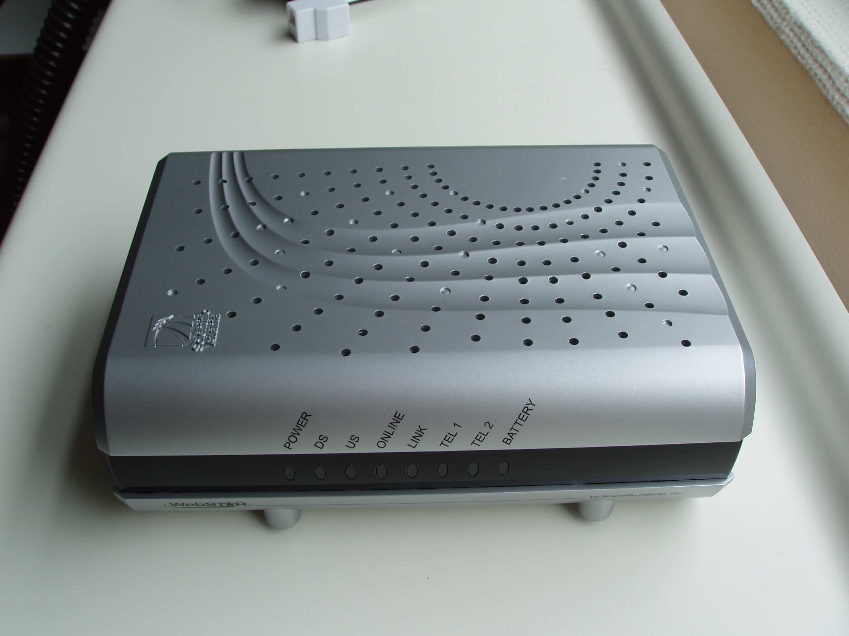
Click to zoom
Application Details
- Equipment Class
- PUB - Part 15 Unlicensed PCS Base Station
- Date of Grant
- Aug 09, 2006
- Application Purpose
- Original Equipment
- Date of Application
- Aug 09, 2006
- Equipment Note
- PCS Base Station
- Frequency Range
- 1921.53600000 - 1928.44800000
- Company
- Askey Computer Corp
- Country
- Taiwan
Documents & Files
Document Text
Text extracted from the exhibit documents filed with the FCC. Open a document above to read the original.
Users Manual
Preliminary Draft 02 – 1/26/06 1 WebSTAR™ DPC2223™ and EPC2223™ VoIP Cable Modem with DECT Base Station User’s Guide Introduction Welcome to the exciting world of high-speed Internet and high-quality digital telephone service. Your new WebSTAR™ DPC2223™ or EPC2223™ Voice-over-Internet Protocol (VoIP) Cable Modem with Digitally Enhanced Cordless Telephone (DECT) Base Station is a modem that meets industry standards for high-speed data connectivity along with reliable digital telephone service. With a DPC2223 or EPC2223, your Internet enjoyment, home and business communications, and personal productivity will surely soar. This guide provides procedures and recommendations for placing, installing, configuring, operating, and troubleshooting your DPC2223 or EPC2223 cable modem for high-speed Internet or digital telephone service for your home or office. Refer to the appropriate section in this guide for the specific information you need for your situation. Contact your service provider for more information about subscribing to these services. Benefits and Features Your new DPC2223 or EPC2223 offers the following outstanding benefits and features: • Features an embedded media terminal adapter (EMTA) supporting two-line voice services along with a DECT base station. The DECT base station gives the user the option to support up to four DECT cordless handsets • Provides a high-speed broadband Internet connection that energizes your online experience, such as providing hassle-free downloading and sharing files and photos with your family and friends • Includes 10/100BaseT Ethernet and USB ports to provide connectivity for high-speed data services or to other Internet devices • Assures a broad range of interoperability with most service providers by complying with Data Over Cable System Interface Specifications (DOCSIS ® ) 1.0, 1.1, and 2.0 standards along with PacketCable™ 1.5 specifications to deliver high-end performance and reliability • Includes two RJ-11 telephony ports for connecting conventional telephones or fax machines • Allows you to attach multiple devices in your home or office to the cable modem for high-speed networking and sharing of files and folders without first copying them onto a CD or diskette • Features Plug and Play operation for easy set up and installation • Provides parental control and advanced firewall technology • Utilizes an attractive compact design that allows for vertical, horizontal, or wall-mount placement • Allows automatic software upgrades by your service provider • Optional model includes an internal Lithium-Ion cartridge-style battery for convenient and long-lasting backup power WebSTAR DPC2223 and EPC2223 VoIP Cable Modem User’s Guide Preliminary Draft 02 – 1/26/06 2 Notice for CATV Installers CATV Installers Notice If you are a CATV installer, read the information in the box below. In This Guide 3 In This Guide IMPORTANT SAFETY INSTRUCTIONS ...................................................................................................................4 What’s In the Carton? .................................................................................................................................................8 Front Panel Description ..............................................................................................................................................9 Back Panel Description ............................................................................................................................................10 Where Is the Best Location for My Cable Modem?..................................................................................................11 What Are the System Requirements for Internet Service?.......................................................................................11 How Do I Set Up My High-Speed Internet Access Account? ...................................................................................12 How Do I Connect My Devices to Use the Internet? ................................................................................................13 How Do I Configure TCP/IP Protocol? .....................................................................................................................15 How Do I Install USB Drivers?..................................................................................................................................18 What Are the Requirements for Ethernet Network Devices? ...................................................................................20 How Do I Select and Place Ethernet Network Devices? ..........................................................................................21 How Do I Connect Ethernet Network Devices?........................................................................................................22 What Are the Requirements for USB Network Devices? .........................................................................................24 How Do I Select and Place USB Network Devices? ................................................................................................25 How Do I Connect USB Network Devices? ..............................................................................................................26 Troubleshooting My Internet Service Installation? ...................................................................................................28 How Do I Use My Modem for Telephone Service? ..................................................................................................30 Where Do I Place My Modem for Telephone Service? ............................................................................................31 What Are the Requirements for Telephone Service?...............................................................................................32 How Do I Install the Modem for Telephone Service? .........................................…
Text truncated - open the document above for the full version.
External Photos
FCC ID: H8NPKE525VB Project no.: 58344 Page 1 of 2 Nemko Comlab, Kjeller, Norway EXTERNAL PHOTOS - DPC2223 DECT BASE STATION FCC ID: H8NPKE525VB Project no.: 58344 Page 2 of 2 Nemko Comlab, Kjeller, Norway Power Adaptor
Internal Photos
FCC ID: H8NPKE525VB Project no.: 58344 Page 1 of 3 Nemko Comlab, Kjeller, Norway INTERNAL PHOTOS - DPC2223 DECT BASE STATION DPC2223 – Radiated Sample FCC ID: H8NPKE525VB Project no.: 58344 Page 2 of 3 Nemko Comlab, Kjeller, Norway DPC2223 – Radiated Sample Without Shielding FCC ID: H8NPKE525VB Project no.: 58344 Page 3 of 3 Nemko Comlab, Kjeller, Norway DPC2223 – Conducted Sample
RF Exposure Info
Prediction of MPE limit at a given distance Equation from page 18 of OET Bulletin 65, Edition 9 7-01 where: S = power density P = power input to the antennaG = power gain of the antenna in the direction of i nterest relative to an isotropic radiator R = distance to the center of radiation of the ante nna Maximum peak output power at antenna input terminal : 18,30 (dBm) Maximum peak output power at antenna input terminal : 67,61 (mW) Antenna gain(typical): 5,00 (dBi) Maximum antenna gain: 3,16 (numeric) Prediction distance: 20 (cm) Prediction frequency: 1921,5 (MHz) MPE limit for uncontrolled exposure at prediction f requency: 1,00 (mW/cm^2) Power density at prediction frequency: 0,042533 (mW/cm^2) Maximum allowable antenna gain: 18,71 (dBi) Margin of Compliance: 13,71 (dB) 2 4 R PG S π =
Test Report
UPCS – Compliance Information EUT AND PRODUCT INFORMATION Type of Equipment US DECT UPCS Model name DPC2223 FP PP Repeater EUT Type/System HW Version PKE525VB-D17(DECT) Version: EOHA SW Version v1.11 DECT SW RFPI / PIN 00 00 00 00 10 Max. Peak Power (dBm) 18.3 Emission BW (MHz) 1.3 Receive Bandwidth (MHz) Does the EUT transmit signaling channels Lower Threshold (dBm) 80.6 Upper Threshold (dBm) 60.6 Test standard: FCC part 15D Other Frequency Band 1921.536 – 1928.448 MHz # of RF Channels 5 Frame Period 10 ms Max. Burst length 390 μs Min. Burst Length 390 μs # of Logical Channels 60 (12 duplex channels per RF carrier) Slot Type Single Double Operating Mode Simplex Duplex 060628_part_15d_declarations 16-Feb-2006 page 1 (6) rev.1.1 UPCS – Compliance Information ANTENNAS Antenna Type Gain (dBi)Internal External 1 Internal Inverted –F PCB Antenna (1/4 wawe antenna) 5 2 3 4 Base (FP) Does RX and TX use the same antenna(s)? Yes No Antenna Type Gain (dBi)Internal External 1 2 Handset (PP) Does RX and TX use the same antenna(s)? Yes No ANTENNA DIVERSITY Diversity Supported Antenna TX RX 1 2 3 Base (FP) 4 1 Handset (PP) 2 060628_part_15d_declarations 16-Feb-2006 page 2 (6) rev.1.1 UPCS – Compliance Information VOLTAGE AND TEMPERATURE RANGES VOLTAGES FP PP Repeater Max Temperature (°C) Min Temperature (°C) Nominal Voltage Cut-Off Voltage (if applicable) POWER SOURCE Type Manufacturer Base or Repeater Plug In Class II Power Unit AD-515A OEM® Handset (PP) (charger) Data Connections PSTN Others (please specify): Cable Modem ANCILLARY EQUIPMENT Description Type Manufacturer HOST DEVICE Description Type Manufacturer ADDITIONAL INFORMATION 060628_part_15d_declarations 16-Feb-2006 page 3 (6) rev.1.1 UPCS – Compliance Information MANUFACTURERS DECLARATIONS FCC part 15.323 (c)(5) No device or group of co-operating devices located within 1 meter of each other shall during any frame period occupy more than 6 MHz of aggregate bandwidth, or alternatively, more than one third of the time and spectrum windows defined by the system. Applicant Agrees Yes No FCC part 15.323 (c)(10) The applicant hereby declares that system in this application does not use the criteria of (c)(10) of this section. Applicant Agrees Yes No FCC part 15.323 (c)(11) The applicant hereby declares that system in this application does not use the criteria of (c)(11) of this section. Applicant Agrees Yes No FCC part 15.323 (c)(12) The provisions of (c)(10) or (c)(11) of this section shall not be used to extend the range of spectrum occupied over space or time for the purpose of denying fair access to spectrum to other devices. Applicant Agrees Yes No FCC part 15.307 (b) The Applicant is a participating member of UTAM, Inc. and will provide an affidavit from UTAM, Inc. certifying this. Confirmed By Applicant Yes No FCC part 15.319 (f) The device shall automatically discontinue transmission in case of either absence of information to transmit or operational failure. These provisions are not intended to preclude transmission of control and signaling information or use of repetitive codes used by certain digital technologies to complete frame or burst intervals. Please explain how compliance with the requirement is obtained: Currently the following precautions are taken to ensure that the Base does not transmit due to an operational failure - See schedule next page: 060628_part_15d_declarations 16-Feb-2006 page 4 (6) rev.1.1 UPCS – Compliance Information Reaction of EUT Situation FP PP Verdict 1 Switch-off counter part B 2 Hook-on by counter part B 3 Switch-off by EUT A 4 Hook-on at EUT side Not possible 5 Remove Power from EUT A 6 Remove Power from Counterpart B A – Connection break down, cease of transmit B – Connection break down, EUT transmits signaling information C – Connection break down, counter part transmits signaling information Confirmed By Applicant Yes No ADDITIONAL REMARKS: The equipment is a Cable modem with an integrated DECT Base station. The equipment also has two connections for analog telephones and a USB connection for connection to a computer. DECLARED BY: >June 22, 2006 Date >Michael Jeng Name (print) Signature 060628_part_15d_declarations 16-Feb-2006 page 5 (6) rev.1.1 UPCS – Compliance Information 060628_part_15d_declarations 16-Feb-2006 page 6 (6) rev.1.1
Test Report
Nemko AS, Gaustadalléen 30, P.O.Box 73 Blindern, NO-0314 Oslo Norway T +47 22 96 03 30 F +47 22 96 05 50 Enterprise number NO974404532 Visiting address: Nemko Comlab, Gåsevikveien 8, P.O.Box 96, NO-2027 Kjeller Norway T +47 64 84 57 00 F +47 64 84 57 05 Test report no. : 58344-7 Item tested : DPC2223 Type of equipment : Isochronous UPCS Device FCC ID : H8NPKE525VB Client : Askey Computer Corp. FCC Part 15, subparts B and D Isochronous UPCS Device 1920 - 1930 MHz Industry Canada RSS-213, Issue 2 2 GHz Licence-exempt Personal Communications Service Devices (LE-PCS) 7 August 2006 Authorized by : .............................................. Egil Hauger Technical Verificator TEST REPORT FCC part 15D Project no.: 58344 FCC ID: H8NPKE525VB Nemko Comlab, N-2027 Kjeller Page 2 (58) CONTENTS 1 GENERAL INFORMATION...........................................................................................................................3 1.1 Tested by.......................................................................................................................................................3 1.2 Client Information ..........................................................................................................................................3 1.3 Manufacturer ( if other than client) ................................................................................................................3 2 Test Information ..........................................................................................................................................4 2.1 Tested Item ...................................................................................................................................................4 2.2 Test Environment ..........................................................................................................................................5 2.3 Test Period ....................................................................................................................................................5 2.4 Test Engineer ................................................................................................................................................5 2.5 Test Equipment .............................................................................................................................................5 2.6 Other Comments ...........................................................................................................................................5 3 TEST REPORT SUMMARY..........................................................................................................................6 3.1 General..........................................................................................................................................................6 3.2 Test Summary ...............................................................................................................................................7 4 TEST RESULTS ...........................................................................................................................................8 4.1 Power-line Conducted Emissions..................................................................................................................8 4.2 Coordination with fixed microwave ..............................................................................................................10 4.3 Digital Modulation Techniques ....................................................................................................................10 4.4 Labelling Requirements...............................................................................................................................10 4.5 Antenna Requirement .................................................................................................................................11 4.6 Channel Frequencies ..................................................................................................................................11 4.7 Automatic Discontinuation of Transmission ................................................................................................12 4.8 Peak Power Output .....................................................................................................................................13 4.9 Emission Bandwidth B.................................................................................................................................16 4.10 Power Spectral Density ...............................................................................................................................20 4.11 In-band Unwanted Emissions, Conducted ..................................................................................................22 4.12 Out-of-band Emissions, Conducted ............................................................................................................24 4.13 Carrier Frequency Stability ..........................................................................................................................27 4.14 Frame Repetition Stability ...........................................................................................................................28 4.15 Frame Period and Jitter ...............................................................................................................................28 4.16 Monitoring Threshold, Least Interfered Channel .........................................................................................31 4.17 Threshold Monitoring Bandwidth .................................................................................................................33 4.18 Reaction Time and Monitoring Interval........................................................................................................34 4.19 Time and Spectrum Window Access Procedure ........…
Text truncated - open the document above for the full version.
Test Setup Photos
FCC ID: H8NPKE525VB Project no.: 58344 Page 1 of 2 Nemko Comlab, Kjeller, Norway PHOTOS OF TEST SET-UP DPC2223 - Radiated emissions test, 3m FCC ID: H8NPKE525VB Project no.: 58344 Page 2 of 2 Nemko Comlab, Kjeller, Norway DPC2223 - Power line Conducted Emissions Test
Contact Information
Applicant
Jack Po(Manager)
Technical Contact
Non-Technical Contact
Nemko Comlab A/SGeir Antonsen
[email protected]+47 64 84 57 15
Test Firm
Nemko Canada Inc. (Ottawa)Charles Neal
Technical Specifications
| # | Rule Parts | Frequency Range | Power Output |
|---|---|---|---|
| 1 | 15D | 1.92 GHz - 1.93 GHz | 70.00 mW |
Other Applications from Askey Computer Corp
H8N-NUQ2006
Sep 11, 2026enterprise-grade 5G NR outdoor unit
Equipment Class
CBD - Citizens Band Category A and B DevicesH8NSCU5000
Jun 18, 20265G Small cell
Equipment Class
CBD - Citizens Band Category A and B DevicesH8N-EAI2620P
Jan 29, 2026Indoor Wi-Fi 7 Enterprise Access Point
Equipment Class
DTS - Digital Transmission SystemH8N-CTX0800
Oct 07, 2024OBU
Equipment Class
NII - Unlicensed National Information Infrastructure TX
H8NEAO2522P-2
Jul 04, 2024Outdoor WiFi6 AP
Equipment Class
DTS - Digital Transmission System