H8NWLL220C2.4GHz/5GHz Mini-PCI Card
Askey Computer Corp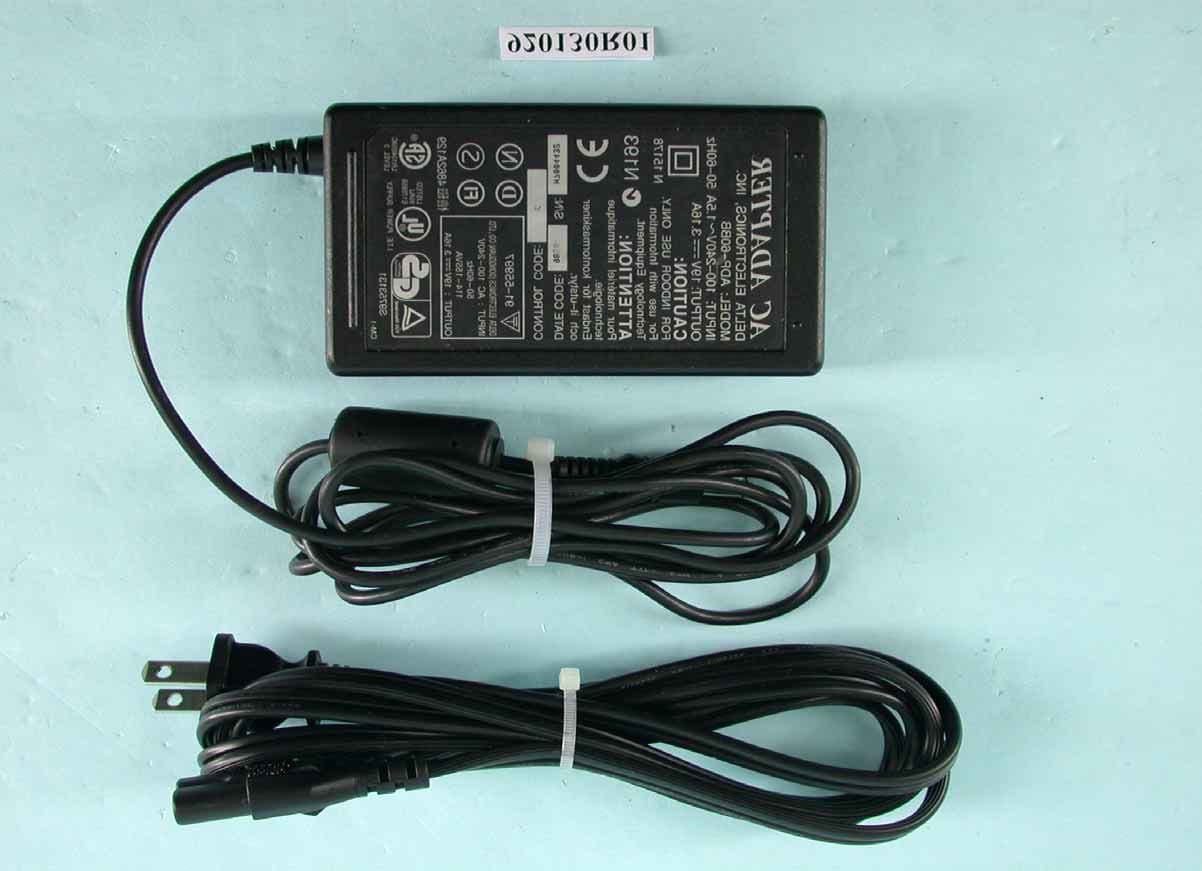
Click to zoom
Application Details
- Equipment Class
- DTS - Digital Transmission System
- Date of Grant
- Nov 12, 2003
- Application Purpose
- Original Equipment
- Date of Application
- Apr 19, 2003
- Equipment Note
- 2.4GHz/5GHz Mini-PCI Card
- Frequency Range
- 2412.00000000 - 2462.00000000
- Company
- Askey Computer Corp
- Country
- Taiwan
Documents & Files
Document Text
Text extracted from the exhibit documents filed with the FCC. Open a document above to read the original.
Users Manual
802.11a/b/g Combo Mini PCI WLAN CardUser’s Manual 2003 All rights reserved. No part of this document may be reproduced or transmitted in any form or by any means, electronic or mechanical, for any purpose, without the express written permission of the seller. DisclaimerInformation in this document is subject to change without noti ce. The material contained herein is supplied without representat ion or warranty of any kind. The seller therefore assumes no responsibility and shall have no liability of any kind arising from the supply or use of this document or the material contained herein. TrademarksMicrosoft and Windows are registered trademar ks of Microsoft Corporation. GUI and Ethern et is a registered trademark of Xeros C orporation. Atheros and the Atheros logo are registered trademar ks of Atheros Communications, Inc. Cisco, Cisco Systems, and the Cisco Systems log o are registered trademarks of Cisco Systems, Inc. and/or its affiliates in the U.S. and certain other countries. All other trademarks mentioned in this document are the property of their respective owners.Date: April 2003Part No. A230XPRev01 I ContentsChapter 1 Introduction ............................................................................................................................... ................. 1 Wireless LAN Basics ............................................................................................................................... .................... 2 Local Area Network (LAN) ............................................................................................................................... ........ 2 Wireless Network Topologies ............................................................................................................................... ... 3 802.11a, 802.11b and 802.11g ............................................................................................................................... 4 Chapter 2 Installing the Driver and Utility Software ................................................................................................ 5 System Requirements ............................................................................................................................... .................. 6 Installing the driver and software ............................................................................................................................... .6 Chapter 3 Utility Configuration ............................................................................................................................... .11 Accessing the Atheros Configuration Utility .............................................................................................................. 11 Note to Windows XP Users ............................................................................................................................... .... 11 Network Basic Configuration ............................................................................................................................... ...... 12 General Tab ............................................................................................................................... ............................ 12 Security Tab ............................................................................................................................... ........................... 13 Advanced Tab ............................................................................................................................... ........................ 15 Connecting to an Existing Network ........................................................................................................................... 17 Modifying a Configuration Profile .............................................................................................................................. 1 9 Removing a Configuration Profile ............................................................................................................................. 19 Chapter 4 Checking Status or Statistics ................................................................................................................. 21 Status Monitor Tray Icon ............................................................................................................................... ............ 21 Current Status Tab ............................................................................................................................... ..................... 22 Advanced Status ............................................................................................................................... .................... 24 Diagnostics Tab ............................................................................................................................... ......................... 24 Advanced Statistics ............................................................................................................................... ................ 25 Driver Information ............................................................................................................................... ................... 26 Chapter 5 ACU Toolbar ............................................................................................................................... .............. 29 Action Menu ............................................................................................................................... ............................... 29 Options Menu ............................................................................................................................... ............................. 29 Help Menu ............................................................................................................................... .................................. 30 802.11a/b/g Combo Mini PCI…
Text truncated - open the document above for the full version.
Users Manual
第 1 頁,共 1 頁User's manual 2003/6/10 file://C:\WINDOWS\TEMP\~hh63D1.htm Safety Instructions Use the following safety guidelines to help protect yourself and your computer. When Using Your Computer CAUTION: Do not operate your portable computer for an extended period of time with the base resting directly on your body. With extended operation, heat can potentially build up in the base. Allowing sustained contact with the skin could cause discomfort or, eventually, a burn. Do not attempt to service the computer yourself. Always follow installation instructions closely. Do not carry a battery in your pocket, purse, or other container where metal objects (such as car keys) could short-circuit the battery terminals. The resulting excessive current flow can cause extremely high temperatures and may result in damage from burns. Be sure that nothing rests on your AC adapter's power cable and that the cable is not located where it can be tripped over or stepped on. Place the AC adapter in a ventilated area, such as a desk top or on the floor, when you use it to run the computer or to charge the battery. Do not cover the AC adapter with papers or other items that will reduce cooling; also, do not use the AC adapter while it is inside a carrying case. Do not push objects into air vents or openings of your computer. Doing so can cause fire or electric shock by shorting out interior components. Use only the AC adapter and batteries that are approved for use with this computer. Use of another type of battery or AC adapter may risk fire or explosion. Danger of explosion if battery is incorrectly replaced. Replace only with the same or equivalent type battery recommended by by the manufacturer. Dispose of used batteries according to the manufacturer's instructions. Before you connect the computer to a power source, ensure that the voltage rating of the AC adapter matches that of the available power source. - 115 V/60 Hz in most of North and South America and some Far Eastern countries such as South Korea and Taiwan. - 100 V/50 Hz in eastern Japan and 100 V/60Hz in western Japan. - 230 V/50 Hz in most of Europe, the Middle East, and the Far East. If you use an extension cable with your AC adapter, ensure that the total ampere rating of the products plugged in to the extension cable does not exceed the ampere rating of the extension cable. 第 1 頁,共 3 頁Safety Instructions 2003/6/10 file://C:\WINDOWS\TEMP\~hhCC6F.htm To remove power from the computer, turn it off, remove the battery, and and disconnect the AC adapter from the electrical outlet. To help avoid the potential hazard of electric shock, do not connect or disconnect any cables or perform maintenance or reconfiguration of this this product during an electrical storm. Do not dispose of batteries in a fire. They may explode. Check with local authorities for disposal instructions. When setting up the computer for work, place it on a level surface. When traveling, do not check the computer as baggage. You can put your computer through an X-ray security machine, but never put your computer through a metal detector. If you have the computer checked by hand, be sure to have a charged battery available in case you are asked to turn on the computer. When traveling with the hard drive removed from the computer, wrap the drive in a non-conducting material, such as cloth or paper. If you have the drive checked by hand, be ready to install the drive in the computer. Your can put the hard drive through an X-ray security machine, but never put the drive through a metal detector. When traveling, do not place the computer in overhead storage compartments where it could slide around. Do not drop your computer or subject it to other mechanical shocks. Protect your computer, battery, and hard drive from environmental hazards such as dirt, dust, food, liquids, temperature extremes, and overexposure to sunlight. When you move your computer between environments with very different temperature and/or humidity ranges, condensation may form on or within the computer. To avoid damaging the computer, allow sufficient time for the moisture to evaporate before using the computer. NOTICE: When taking the computer from low-temperature conditions into a warmer environment or from high-temperature conditions into a cooler environment, allow the computer to acclimate to room temperature before turning on power. When you disconnect a cable, pull on its connector or on its strain relief relief loop, not on the cable itself. As you pull out the connector, keep it evenly aligned to avoid bending any connector pins. Also, before you connect a cable make sure both connectors are correctly oriented and aligned. Before you clean your computer, turn if off, unplug it from its power source, and remove the battery. Handle components with care. Hold a component such as a memory module by its edges, not its pins. CAUTION: When using your telephone equipment, basic safety precautions should always be followed to reduce the risk of fire, electric shock and injury to persons, including the following: Do not use this product near water, for example, near a bathtub, washing bowl, kitchen sink or laundry tub, in a wet basement or near a swimming pool. Avoid using a telephone (other than a cordless type) during an electrical 第 2 頁,共 3 頁Safety Instructions 2003/6/10 file://C:\WINDOWS\TEMP\~hhCC6F.htm electrical storm. There may be a remote risk of electric shock from lightning. Do not use the telephone to report a gas leak in the vicinity of the leak. Use only the power cord indicated in this manual. 第 3 頁,共 3 頁Safety Instructions 2003/6/10 file://C:\WINDOWS\TEMP\~hhCC6F.htm Appendix: Regulatory Notices The FCC wants you to know Federal Communications Commission (FCC) PART 68 Warning REN: 0.8B CE Notice (European Union) CCIB Notice (China Only) BSMI Notice (Taiwan Only) Canadian Doc Notice About this user's manual The FCC wants you to know This equipment has been tested and found to comply with the limits …
Text truncated - open the document above for the full version.
External Photos
Page 1 ANNEX PHOTOGRAPHS OF EUT Page 2 Page 3 Page 4 Page 5 Page 6 Page 7
ID Label/Location Info
6.0 3.0 9.5 9.0 9.0 Align C.L 9.0 9.0 8.0 8.0 1.0 2.3 6.8 0.2 7.0 7.0 0.2 9.0 Align C.L of opening 7.6 1.6 7.8 A l i g n C . L o f o p e n i n g 5.0 5.3 9.5 Align C.L of opening 7.0 1.2 Align C.L 1 8 0.5 7.8
Internal Photos
Page 8 Page 9 Page 10 Page 11 Page 12 Page 13 Page 14
Operational Description
FCC ID: H8NWLL220C ADT No.920130R01 Technical Description The transmitter of the EUT (2.4GHz/5GHz Mini - PCI Card) is powered by host equipment and pluged in Mini PCI slot. The antenna is T-type antenna with UFL antenna connector. This device is a 2.4GHz/5GHz Mini - PCI Card which operates in both of the 5GHz and 2.4GHz bands and can not transmitting simultaneously, the maximum data rate could be 108Mbps. For more detailed instruction, please take a look at the user’s manual. FCC 15.407(c) states : The device shall automatically discontinue transmission in case of either absence of information to transmit or operational failure. These provisions are not intended to preclude the transmission of control or signaling information or the use of repetitive codes used by certain digital technologies to complete frame or burst intervals. Applicants shall include in their application for equipment authorization a description of hoe this requirement is met” Data transmission is always initiated by software, which is then pass down through the MAC, through the digital and analog baseband, and finally to the RF chip. Several special packets (ACKs, CTS, PSPoll, etc...) are initiated by the MAC. There are the only ways the digital baseband portion will turn on the RF transmitter, which it then turns off at the end of the packet. Therefore, the transmitter will be on only while one of the aforementioned packets are being transmitted.
RF Exposure Info
FCC ID: H8NWLL220C Report No.: SA920130R01 1 Issued: March. 10 th 2003 SAR TEST REPORT REPORT NO.: SA920130R01 MODEL NO.: WLL220 RECEIVED: March. 07, 2003 TESTED: March. 07, 2003 APPLICANT: ASKEY COMPUTER CORP. ADDRESS:10F, No.119, CHIENKANG RD, CHUNG-HO, TAIPEI, TAIWAN R.O.C. ISSUED BY:Advance Data Technology Corporation LAB LOCATION:47 14th Lin, Chiapau Tsun, Linko, Taipei, Taiwan, R.O.C. This test report consists of 15 pages in total except Appendix. It may be duplicated completely for legal use with the approval of the applicant. It should not be reproduced except in full, without the written approval of our laboratory. The client should not use it to claim product endorsement by CNLA, NVLAP or any government agencies. The test results in the report only apply to the tested sample. FCC ID: H8NWLL220C Report No.: SA920130R01 2 Issued: March. 10 th 2003 Table of Contents 1.CERTIFICATION .................................................................................................................3 2.GENERAL INFORMATION ................................................................................................. 4 2.1GENERAL DESCRIPTION OF EUT ................................................................................... 4 2.2GENERAL DESCRIPTION OF APPLIED STANDARDS .................................................... 4 2.3GENERAL INOFRMATION OF THE SAR SYSTEM .......................................................... 5 2.4GENERAL DESCRIPTION OF THE PROBE SCAN RULE................................................ 7 3.DESCRIPTION OF TEST MODES AND CONFIGURATIONS ........................................... 8 4.DESCRIPTION OF SUPPORT UNITS ............................................................................... 9 5.TEST RESULTS................................................................................................................ 10 5.1TEST PROCEDURES....................................................................................................... 10 5.2MEASURED SAR RESULT .............................................................................................. 10 5.3SAR LIMITS ...................................................................................................................... 11 5.4EUT CONDUCTED POWER VARIATION ........................................................................ 11 5.5TISSUE ............................................................................................................................. 12 5.6TEST EQUIPMENT FOR TISSUE PROPERTY ............................................................... 12 6.SYSTEM VALIDATION...................................................................................................... 13 7.MEASUREMENT UNCERTAINTIES ................................................................................ 14 8.INFORMATION ON THE TESTING LABORATORIES ..................................................... 15 APPENDIX A: TEST CONFIGURATIONS AND TEST DATA APPENDIX B: ADT SAR MEASUREMENT SYSTEM APPENDIX C: PHOTOGRAPHS OF SYSTEM VALIDATION APPENDIX D: SYSTEM CERTIFICATE & CALIBRATION FCC ID: H8NWLL220C Report No.: SA920130R01 3 Issued: March. 10 th 2003 1. CERTIFICATION PRODUCT : 2.4GHz/5GHz Mini ñ PCI Card MODEL NO. : WLL220 BRAND NAME : ASKEY APPLICANT : ASKEY COUMPTER CORP. STANDARDS : 47 CFR Part 2 (Section 2.1093), FCC OET Bulletin 65, Supplement C (01-01), RSS-102 We, Advance Data Technology Corporation, hereby certify that one sample of the designation has been tested in our facility on 07 th March. 2003. The test record, data evaluation and Equipment Under Test (EUT) configurations represented herein are true and accurate, and it was tested according to the standards listed above. This device was found to be in compliance with the Specific Absorption Rate (SAR) requirement specified in FCC part 2.1093 under General Population / Uncontrolled Exposure condition. FCC ID: H8NWLL220C Report No.: SA920130R01 4 Issued: March. 10 th 2003 2. GENERAL INFORMATION 2.1 GENERAL DESCRIPTION OF EUT PRODUCT2.4GHz/5GHz Mini ñ PCI Card MODEL NO.WLL220 POWER SUPPLY3.3VDC powered by host equipment CLASSIFICATIONPortable device, production unit RADIO TECHNOLOGY DSSS , OFDM TRANSFER RATE 1/2/5.5/11/48/54/Mbps FREQUENCY RANGE2412MHz ~ 2462MHz NUMBER OF CHANNEL11 CONDUCTED OUTPUT POWER 49.15mW ANTENNA TYPEInternal Diversity* PEAK SAR1.21W/kg DATA CABLENA I/O PORTSMini PCI ASSOCIATED DEVICESNA NOTE: Transmitting antenna is located on the right side of the keyboard plate. 2.2 GENERAL DESCRIPTION OF APPLIED STANDARDS According to the specifications of the manufacturer, this product must comply with the requirements of the following standards: FCC 47 CFR Part 2 (2.1093) FCC OET Bulletin 65, Supplement C (01- 01) RSS-102 All tests have been performed and recorded as per the above standards. FCC ID: H8NWLL220C Report No.: SA920130R01 5 Issued: March. 10 th 2003 2.3 GENERAL INOFRMATION OF THE SAR SYSTEM DASY3 (software 3.1d) consists of high precision robtics system, probe alignment sensor, phantom, robot controller, controlled PC and near-field probe. The robot includes six axis that can move to the precision position of the DASY3 software defined. The DASY3 software can define the area which is detected by the probe. The robot is connected to controlled box. Controlled PC is connected to the controlled robot box. The DAE includes amplifier, signal multiplexing, AD converter, offset measurement, surface detection. It is connected to the Electro-optical coupler (ECO). The ECO performs the conversion form the optical into digital electric signal of the DAE and transfers data to the PC. ET3DV6 ISOTROPIC E-FIELD PROBE Construction Symmetrical design with triangular core. Built-in optical fiber for surface detection system. Built-in shielding against static charges. PEEK enclosure material (resistant to organic solvents, e.g., glycolether). Calibration Basic Broad Band Calibration in air: 10-2500 MHz Conversion Factors (C…
Text truncated - open the document above for the full version.
RF Exposure Info
1 Oct. 14, 2003 FCC ID# H8NWLL220C Applicant: Askey Computer Corp. Correspondence Reference Number: 25430 731 Confirmation Number: EA 441634 A3) Details of power measurement made for SAR. Are these peak or average? What is BW of measurement equipment? Response: There is a typo in the caption of Table 1on p. 12 of the SAR report . The caption should read " Peak conducted RF power" rather than Average conducted RF power. The procedure for conducted output power measurements used the channel power function of the Spectrum Analyzer Model FSEK 30. Attach an appendix giving the power outputs for various channels. 2 Appendix PEAK TRANSMIT POWER MEASUREMENT LIMITS OF PEAK TRANSMIT POWER MEASUREMENT Frequency Band Limit 5.15 – 5.25GHz The lesser of 50mW (17dBm) or 4dBm + 10logB 5.25 – 5.35GHz The lesser of 250mW (24dBm) or 11dBm + 10logB 5.725 – 5.825GHz The lesser of 1W (30dBm) or 17dBm + 10logB NOTE: Where B is the 26dB emission bandwidth in MHz. TEST INSTRUMENTS Description & Manufacturer Model No. Serial No. Calibrated Until SPECTRUM ANALYZER FSEK30 100049 July 24, 2003 NOTE: The measurement uncertainty is less than +/- 2.6dB, which is calculated as per the NAMAS document NIS81. 3 TEST PROCEDURE 1. The transmitter output was connected to the spectrum analyzer. 2. Set span to encompass the entire emission bandwidth of the signal. 3. Set RBW to 1MHz, VBW to 300kHz. 4. Using the spectrum analyzer’s channel power measurement function to measure the output power. DEVIATION FROM TEST STANDARD No deviation TEST SETUP EUT OPERATING CONDITIONS The software provided by client to enable the EUT under transmission condition continuously at specific channel frequencies individually. EUT SPECTRUM 4 TEST RESULTS – NORMAL MODE EUT 2.4GHz/5GHz Mini - PCI Card MODEL WLL220 ENVIRONMENTAL CONDITIONS 24deg. C, 67%RH, 991hPa INPUT POWER (SYSTEM) 120Vac, 60 Hz TESTED BY Ansen Lei CHANNEL CHANNEL FREQUENCY (MHz) PEAK POWER OUTPUT (dBm) PEAK POWER LIMIT (dBm) 26dBc Occupied Bandwidth (MHz) PASS/FAIL 1 5180 15.63 17.00 28.30 PASS 4 5240 16.07 17.00 27.25 PASS 5 5260 20.22 24.00 26.77 PASS 8 5320 17.87 24.00 27.33 PASS 9 5745 18.92 30.00 27.17 PASS 12 5805 18.33 30.00 27.25 PASS NOTE: The 26dBc Occupied Bandwidth plot, please refer to the following pages. 5 CHANNEL 1 6 CHANNEL 4 7 CHANNEL 5 8 CHANNEL 8 9 CHANNEL 9 10 CHANNEL 12 11 CHANNEL 1 12 CHANNEL 4 13 CHANNEL 5 14 CHANNEL 8 15 CHANNEL 9 16 CHANNEL 12 17 TEST RESULTS – TURBO MODE EUT 2.4GHz/5GHz Mini - PCI Card MODEL WLL220 ENVIRONMENTAL CONDITIONS 24deg. C, 67%RH, 991hPa INPUT POWER (SYSTEM) 120Vac, 60 Hz TESTED BY Ansen Lei CHANNEL CHANNEL FREQUENCY (MHz) PEAK POWER OUTPUT (dBm) PEAK POWER LIMIT (dBm) 26dBc Occupied Bandwidth (MHz) PASS/FAIL 1 5210 15.72 17.00 50.38 PASS 2 5250 15.65 17.00 49.78 PASS 3 5290 20.25 24.00 49.54 PASS 4 5760 18.88 30.00 48.58 PASS 5 5800 16.28 30.00 48.22 PASS NOTE: The 26dBc Occupied Bandwidth plot, please refer to the following pages. 18 CHANNEL 1 19 CHANNEL 2 20 CHANNEL3 21 CHANNEL 4 22 CHANNEL 5 23 CHANNEL 1 24 CHANNEL 2 25 CHANNEL 3 26 CHANNEL 4 27 CHANNEL 5 28
RF Exposure Info
1 October 14, 2003 Applicant: Askey Computer Corporation FCC ID# H8NWLL220C Correspondence Reference Number: 25430 731 Confirmation Number: EA441634 Date of Original E-mail: 7/9/2003 We are sorry for the delay in responding to your questions on the above subject caused by Dr. Alan Lane leaving ADT Corporation. The responses are as follows: 1. Justification of system operation. Validation measurements appear to be made on 1/03/03 while data was measured on 3/7/03. Provide new validation as appropriate. Please repeat worst-case SAR configuration to show agreement with original test. Response: We do not see the above dates in the SAR Report for this EUT submitted on March 20, 2003 (attached as Appendix I). As given on page 5, as well as in Appendix B (p. 49) of the SAR Report, the date for system validation as well as for all of the SAR measurements was March 17, 2003. 2. Additional SAR data as follows: – Left antenna – worst-case frequency from right side is sufficient. – Sample of other data rates at worst-case configuration to demonstrate that there is no effect on SAR. Response: The measured SAR data are given in Table 11 both for the right- and left-side antennas marked as antennas "A" and "B", respectively. For the normal (base) and turbo modes, the frequencies selected for SAR testing were those with the highest power outputs as well as to cover both the low and the high frequency bands (see Table 1 on p. 12 of Appendix I). A3) Details of power measurement made for SAR. Are these peak or average? What is BW of measurement equipment? Response: There is a typo in the caption of Table 1on p. 12 of the SAR report . The caption should read " Peak conducted RF power" rather than Average conducted RF power. The procedure for conducted output power measurements used the channel power function of the Spectrum Analyzer Model FSEK 30. Attach an appendix giving the power outputs for various channels. 2 Appendix PEAK TRANSMIT POWER MEASUREMENT LIMITS OF PEAK TRANSMIT POWER MEASUREMENT Frequency Band Limit 5.15 – 5.25GHz The lesser of 50mW (17dBm) or 4dBm + 10logB 5.25 – 5.35GHz The lesser of 250mW (24dBm) or 11dBm + 10logB 5.725 – 5.825GHz The lesser of 1W (30dBm) or 17dBm + 10logB NOTE: Where B is the 26dB emission bandwidth in MHz. TEST INSTRUMENTS Description & Manufacturer Model No. Serial No. Calibrated Until SPECTRUM ANALYZER FSEK30 100049 July 24, 2003 NOTE: The measurement uncertainty is less than +/- 2.6dB, which is calculated as per the NAMAS document NIS81. 3 TEST PROCEDURE 1. The transmitter output was connected to the spectrum analyzer. 2. Set span to encompass the entire emission bandwidth of the signal. 3. Set RBW to 1MHz, VBW to 300kHz. 4. Using the spectrum analyzer’s channel power measurement function to measure the output power. DEVIATION FROM TEST STANDARD No deviation TEST SETUP EUT OPERATING CONDITIONS The software provided by client to enable the EUT under transmission condition continuously at specific channel frequencies individually. EUT SPECTRUM 4 TEST RESULTS – NORMAL MODE EUT 2.4GHz/5GHz Mini - PCI Card MODEL WLL220 ENVIRONMENTAL CONDITIONS 24deg. C, 67%RH, 991hPa INPUT POWER (SYSTEM) 120Vac, 60 Hz TESTED BY Ansen Lei CHANNEL CHANNEL FREQUENCY (MHz) PEAK POWER OUTPUT (dBm) PEAK POWER LIMIT (dBm) 26dBc Occupied Bandwidth (MHz) PASS/FAIL 1 5180 15.63 17.00 28.30 PASS 4 5240 16.07 17.00 27.25 PASS 5 5260 20.22 24.00 26.77 PASS 8 5320 17.87 24.00 27.33 PASS 9 5745 18.92 30.00 27.17 PASS 12 5805 18.33 30.00 27.25 PASS NOTE: The 26dBc Occupied Bandwidth plot, please refer to the following pages. 5 CHANNEL 1 6 CHANNEL 4 7 CHANNEL 5 8 CHANNEL 8 9 CHANNEL 9 10 CHANNEL 12 11 CHANNEL 1 12 CHANNEL 4 13 CHANNEL 5 14 CHANNEL 8 15 CHANNEL 9 16 CHANNEL 12 17 TEST RESULTS – TURBO MODE EUT 2.4GHz/5GHz Mini - PCI Card MODEL WLL220 ENVIRONMENTAL CONDITIONS 24deg. C, 67%RH, 991hPa INPUT POWER (SYSTEM) 120Vac, 60 Hz TESTED BY Ansen Lei CHANNEL CHANNEL FREQUENCY (MHz) PEAK POWER OUTPUT (dBm) PEAK POWER LIMIT (dBm) 26dBc Occupied Bandwidth (MHz) PASS/FAIL 1 5210 15.72 17.00 50.38 PASS 2 5250 15.65 17.00 49.78 PASS 3 5290 20.25 24.00 49.54 PASS 4 5760 18.88 30.00 48.58 PASS 5 5800 16.28 30.00 48.22 PASS NOTE: The 26dBc Occupied Bandwidth plot, please refer to the following pages. 18 CHANNEL 1 19 CHANNEL 2 20 CHANNEL3 21 CHANNEL 4 22 CHANNEL 5 23 CHANNEL 1 24 CHANNEL 2 25 CHANNEL 3 26 CHANNEL 4 27 CHANNEL 5 28
RF Exposure Info
1 October 23 2003 Applicant: Askey Computer Corporation FCC ID# H8NWLL220C Correspondence Reference Number: 25430 731 Confirmation Number: EA441634 Date of Original E-mail: 7/9/2003 We are sorry for the delay in responding to your questions on the above subject caused by Dr. Alan Lane leaving ADT Corporation. The responses are as follows: 1. Justification of system operation. Validation measurements appear to be made on 1/03/03 while data was measured on 3/7/03. Provide new validation as appropriate. Please repeat worst-case SAR configuration to show agreement with original test. Response: We are sorry for the typing error on the validation measurements. The corrected validation measurement have been resubmitted.(See p26 of appendix A for system validation). 2. Additional SAR data as follows: – Left antenna – worst-case frequency from right side is sufficient. – Sample of other data rates at worst-case configuration to demonstrate that there is no effect on SAR. Response: SAR test report have been revised , the measured SAR data are given on page 11 for both antenna. A3) Details of power measurement made for SAR. Are these peak or average? What is BW of measurement equipment? Response: Narda shottky diode-detector was used to test the power, the BW of this detector is 18GHz. The measured power level via this diode is only 0.3dB higher than that of peak power meter. So, for convenience, we use peak power meter to test the output power of the EUT before and after the SAR testing because it is the power deviation which we mainly concern.
RF Exposure Info
FCC ID: H8NWLL220C Report No.: SA920130R01 1 Issued: March. 10 th 2003 SAR TEST REPORT REPORT NO.: SA920130R01 MODEL NO.: WLL220 RECEIVED: March. 07, 2003 TESTED: March. 07, 2003 APPLICANT: ASKEY COMPUTER CORP. ADDRESS: 10F, No.119, CHIENKANG RD, CHUNG-HO, TAIPEI, TAIWAN R.O.C. ISSUED BY: Advance Data Technology Corporation LAB LOCATION: 47 14th Lin, Chiapau Tsun, Linko, Taipei, Taiwan, R.O.C. This test report consists of 17 pages in total except Appendix. It may be duplicated completely for legal use with the approval of the applicant. It should not be reproduced except in full, without the written approval of our laboratory. The client should not use it to claim product endorsement by CNLA, NVLAP or any government agencies. The test results in the report only apply to the tested sample. FCC ID: H8NWLL220C Report No.: SA920130R01 2 Issued: March. 10 th 2003 Table of Contents 1. CERTIFICATION............................................................................................................... 3 2. GENERAL INFORMATION ............................................................................................... 4 2.1 GENERAL DESCRIPTION OF EUT ...................................…
Text truncated - open the document above for the full version.
Contact Information
Applicant
Jack Po(Manager)
Technical Contact
Advance Data Technology CorporationAlan Lane
[email protected]+886 3 327 0910
13-1, Lane 19, WenShan 3rd St · Taoyuan · Taiwan
Non-Technical Contact
AmericanTCBWilliam Graff
[email protected]703 847 4700
Test Firm
Bureau Veritas CPS (H.K.) Ltd. Taoyuan BranchRichard Chen
Technical Specifications
| # | Rule Parts | Frequency Range | Power Output |
|---|---|---|---|
| 1 | 15C | 2.41 GHz - 2.46 GHz | 50.00 mW |
Other Applications from Askey Computer Corp
H8N-NUQ2006
Sep 11, 2026enterprise-grade 5G NR outdoor unit
Equipment Class
CBD - Citizens Band Category A and B DevicesH8NSCU5000
Jun 18, 20265G Small cell
Equipment Class
CBD - Citizens Band Category A and B DevicesH8N-EAI2620P
Jan 29, 2026Indoor Wi-Fi 7 Enterprise Access Point
Equipment Class
DTS - Digital Transmission SystemH8N-CTX0800
Oct 07, 2024OBU
Equipment Class
NII - Unlicensed National Information Infrastructure TX
H8NEAO2522P-2
Jul 04, 2024Outdoor WiFi6 AP
Equipment Class
DTS - Digital Transmission System