HBOHX-P240AJam Plus
SHENZHEN FENDA TECHNOLOGY CO., LTD.Application Details
- Equipment Class
- DSS - Part 15 Spread Spectrum Transmitter
- Date of Grant
- Jan 18, 2014
- Application Purpose
- Original Equipment
- Date of Application
- Jan 18, 2014
- Equipment Note
- Jam Plus
- Frequency Range
- 2402.00000000 - 2480.00000000
- Country
- China
Documents & Files
Document Text
Text extracted from the exhibit documents filed with the FCC. Open a document above to read the original.
Users Manual
WIRELESS SPEAKER PLUSPLUS L – MONO – R Por manual de instrucciones e Información de garantía en español visítenos en www.hmdxaudio.com Thank you for spreading the Jam and purchasing the HMDX Jam Plus Wireless Speaker. Be sure to check out the entire JAM product line on our website: www.hmdxaudio.com — Where there’s a Jam there’s a party! Approximately 3 hours required for full charge. Can be charged by using the USB to Micro USB cord (included) through computer or AC adapter with USB jack (not included). Note: Battery will last up to 4 hours when connected wirelessly. Package Contents User Manual Charging Cord Jam Plus Charging the Unit Controls Power Button Speaker Mode Switch Charging Port Line-in Audio Jack Battery Status Indicator Volume Down Play/Pause Button Volume Up Bluetooth ® Indicator Jam 2 Indicators Solid Red Note: When unit is fully charged Red light will be o . Charging Low Battery Slow Blinking Red Status Battery Indicator Quickly Flash BLUEPairing Mode Paired Line-In Mode Slowly Flash BLUE RED Status Bluetooth Indicator 1 1 2 2 3 3 4 4 5 5 6 6 7 7 8 9 10 8 9 10 To pair 2 Jam Plus speakers together for stereo sound please follow the below steps: 1. Turn 1 speaker over and move the speaker mode switch to L. 2. Turn the other speaker over and move the speaker mode switch to R. 3. Press and hold power button for 5 seconds on one speaker. 4. Press and hold power button for 5 seconds on other speaker. 5. Speakers will begin to pair together automatically. Pairing 2 Jam Plus speakers together (Stereo) To listen to your music over Bluetooth wireless connection, you need to pair your device with Jam Plus: 1. Make sure your device has Bluetooth capability. 2. Press and hold power button for 5 seconds; indicator will begin to ash. 3. Follow the instructions of your device to pair the unit. 4. Pair your device with the unit by selecting JAM PLUS from your Bluetooth listings on your device or selecting YES. 5. Press play on your device and use controls on the unit to adjust desired volume. NOTE: • Once you have successfully paired your device, you may not need to repeat the above steps. Please ensure the AUX cable is unplugged and your device has been Bluetooth enabled. • When using only one Jam Plus, make sure that the switch is set to Mono. You will not be able to pair with the speaker if it is set to “L” or “R”. • When pairing with a computer, please consult your computer manufacturer for Bluetooth pairing instructions and/or the latest Bluetooth Drivers. • A pairing code is not required. Pairing a Single Jam Plus Speaker (Mono) Instruction Manual and Warranty Information HX-P240A FCC Disclaimer: One Year Limited Warranty: Note: This device complies with Part 15 of the FCC Rules. Operation is subject to the following two conditions: (1) this device may not cause harmful interference, and (2) this device must accept any interference received, including interference that may cause undesired operation. Note: The manufacturer is not responsible for any radio or TV interference caused by unauthorized modi cations to this equipment. Such modi cations could void the user authority to operate the equipment. Note: This equipment has been tested and found to comply with the limits for a Class B digital device, pursuant to Part 15 of the FCC Rules. These limits are designed to provide reasonable protection against harmful interference in a residential installation. This equipment generates, uses, and can radiate radio frequency energy and, if not installed and used in accordance with the instructions, may cause harmful interference to radio communications. However, there is no guarantee that interference will not occur in a particular installation. If this equipment does cause harmful interference to radio or television reception, which can be determined by turning the equipment o and on, the user is encouraged to try to correct the interference by one or more of the following measures: • Reorient or relocate the receiving antenna. • Increase the separation between the equipment and receiver. • Connect the equipment into an outlet on a circuit di erent from that to which the receiver is connected. • Consult the dealer or an experienced radio/TV technician for help. This device complies with Part 15 of the FCC Rules and Industry Canada licence-exempt RSS standard(s). Operation is subject to the following two conditions: (1) this device may not cause harmful interference, and (2) this device must accept any interference received, including interference that may cause undesired operation. The manufacturer is not responsible for any radio or TV interference caused by unauthorized modi cations to this equipment. Such modi cations could void the user's authority to operate the equipment. Under Industry Canada regulations, this radio transmitter may only operate using an antenna of a type and maximum (or lesser) gain approved for the transmitter by Industry Canada. To reduce potential radio interference to other users, the antenna type and its gain should be so chosen that the equivalent isotropically radiated power (e.i.r.p.) is not more than that necessary for successful communication. For detailed Warranty Instructions and Information visit: http://www.hmdxaudio.com/products/jam-wireless-portable-speaker.html To obtain warranty service on your HMDX product, contact a Consumer Relations Representative by telephone at 1-800-753-3000 or email [email protected] for assistance. Please make sure to have the model number of the product available. Representatives are available 8:30am - 7:00pm EST Monday-Friday. IMPORTANT SAFEGUARDS: When using an electrical product, basic precautions should always be followed, including the following: READ ALL INSTRUCTIONS BEFORE USING • WARNING: Do not place speakers too close to ears. May cause damage to ear drums, especially in young children. • Use this product only for its intended use as described in this manual. Do not use attachments not recommended by HM…
Text truncated - open the document above for the full version.
External Photos
DONGGUAN NTC CO., LTD. FCC ID: HBOHX-P240A Report NO.: NTC1311613F DONGGUAN NTC CO., LTD. FCC ID: HBOHX-P240A Report NO.: NTC1311613F DONGGUAN NTC CO., LTD. FCC ID: HBOHX-P240A Report NO.: NTC1311613F DONGGUAN NTC CO., LTD. FCC ID: HBOHX-P240A Report NO.: NTC1311613F
ID Label/Location Info
F o r 1 s p e a k e r p a i r i n g - s e t t o M o n o 2 s p e a k e r s t e r e o p a i r i n g - s e t 1 t o L , 1 t o R F C C I D : H B O H X - P 2 4 0 Input: 5VDC 500mA Made in China Model HX-P240 I C : 1 0 5 5 0 A - H X P 2 4 0 15.2mm 11.6mm16.2mm 3.2mm 3.3mm 9.3mm A A A
Internal Photos
DONGGUAN NTC CO., LTD. FCC ID: HBOHX-P240A Report NO.: NTC1311613F Bluetooth Antenna DONGGUAN NTC CO., LTD. FCC ID: HBOHX-P240A Report NO.: NTC1311613F DONGGUAN NTC CO., LTD. FCC ID: HBOHX-P240A Report NO.: NTC1311613F Bluetooth Chip
Test Report
DONGGUAN NTC CO., LTD. Report No.: NTC1311613F FCC ID: HBOHX-P240A Page 2 of 56 Table of Contents 1. GENERAL INFORMATION ................................................................................................ 4 1.1 PRODUCT DESCRIPTION FOR EQUIPMENT UNDER TEST.................................................................... 4 1.2 RELATED SUBMITTAL(S) / GRANT (S)................................................................................................ 5 1.3 TEST METHODOLOGY...................................................................................................................... 5 1.4 EQUIPMENT MODIFICATIONS............................................................................................................ 5 1.5 SUPPORT DEVICE............................................................................................................................ 5 1.6 TEST FACILITY AND LOCATION.......................................................................................................... 5 1.7 SUMMARY OF TEST RESULTS........................................................................................................... 6 2. SYSTEM TEST CONFIGURATION .................................................................................... 7 2.1 EUT CONFIGURATION...................................................................................................................... 7 2.2 SPECIAL ACCESSORIES.................................................................................................................... 7 2.3 DESCRIPTION OF TEST MODES......................................................................................................... 7 2.4 EUT EXERCISE................................................................................................................................7 3. CONDUCTED EMISSIONS TEST ...................................................................................... 8 3.1 TEST SET-UP (BLOCK DIAGRAM OF CONFIGURATION)..................................................................... 8 3.2 TEST CONDITION............................................................................................................................. 8 3.3 MEASUREMENT RESULTS................................................................................................................. 8 4. RADIATED EMISSION TEST........................................................................................... 11 4.1 TEST SET-UP (BLOCK DIAGRAM OF CONFIGURATION)................................................................... 11 4.2 MEASUREMENT PROCEDURE......................................................................................................... 12 4.3 LIMIT.............................................................................................................................................. 13 4.4 MEASUREMENT RESULTS ..................................................................................................... 14 5. CHANNEL SEPARATION TEST ...................................................................................... 18 5.1 MEASUREMENT PROCEDURE......................................................................................................... 18 5.2 TEST SET-UP (BLOCK DIAGRAM OF CONFIGURATION)................................................................... 18 5.3 MEASUREMENT RESULTS............................................................................................................... 18 6. 20DB BANDWIDTH.......................................................................................................... 24 6.1 MEASUREMENT PROCEDURE......................................................................................................... 24 6.2 TEST SET-UP (BLOCK DIAGRAM OF CONFIGURATION)................................................................... 24 6.3 MEASUREMENT RESULTS............................................................................................................... 24 7. HOPPING CHANNEL NUMBER ...................................................................................... 25 7.1 MEASUREMENT PROCEDURE......................................................................................................... 30 7.2 TEST SET-UP (BLOCK DIAGRAM OF CONFIGURATION)................................................................... 30 7.3 MEASUREMENT RESULTS............................................................................................................... 30 DONGGUAN NTC CO., LTD. Report No.: NTC1311613F FCC ID: HBOHX-P240A Page 3 of 56 8. TIME OF OCCUPANCY (DWELL TIME).......................................................................... 32 8.1 MEASUREMENT PROCEDURE......................................................................................................... 32 8.2 MEASUREMENT RESULTS............................................................................................................... 32 9. MAXIMUM PEAK OUTPUT POWER ............................................................................... 32 9.1 MEASUREMENT PROCEDURE......................................................................................................... 38 9.2 MEASUREMENT RESULTS............................................................................................................... 38 10. BAND EDGE ..................................................................................................................38 10.1 MEASUREMENT PROCEDURE....................................................................................................... 44 10.2 LIMIT............................................................................................................................................ 44 10.3 MEASUREMENT RESULTS............................................................................................................. 44 11. ANTENNA APPLICATION .....…
Text truncated - open the document above for the full version.
Test Setup Photos
DONGGUAN NTC CO., LTD. FCC ID: HBOHX-P240A Report NO.: NTC1311613F Conducted Emission Radiated Emission
Contact Information
Applicant
frank Chenzhonghua(engineer)
Test Firm
Dongguan NTC Co.,Ltd.,sunm lv sunm lv
[email protected]86-769-22022444
Technical Specifications
| # | Rule Parts | Frequency Range | Power Output |
|---|---|---|---|
| 1 | 15C | 2.40 GHz - 2.48 GHz | 3.06 mW |
Other Applications from SHENZHEN FENDA TECHNOLOGY CO., LTD.
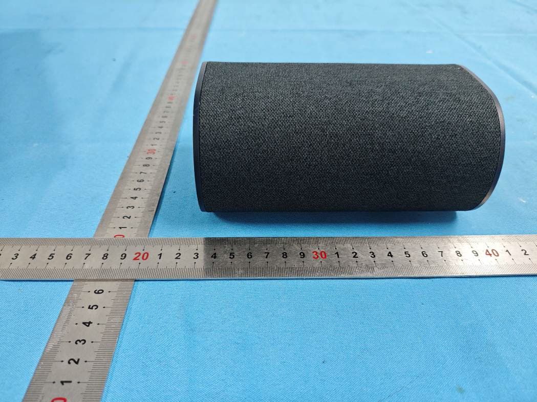
HBOSB2686SU
Aug 20, 20265.1.2 Channel Surround Soundbar
Equipment Class
DTS - Digital Transmission System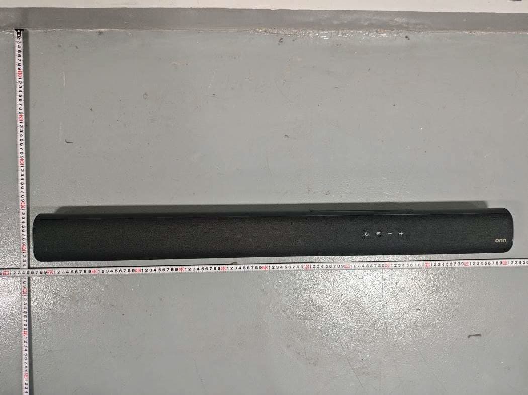
HBOSB2686
Aug 20, 20265.1.2 Channel Surround Soundbar
Equipment Class
DTS - Digital Transmission System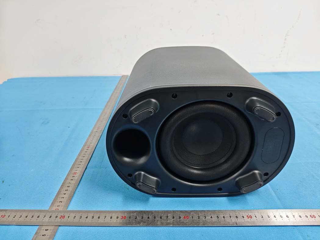
HBOSB2686SW
Aug 20, 20265.1.2 Channel Surround Soundbar
Equipment Class
DTS - Digital Transmission SystemHBOSB2635DDG
Aug 07, 2026Wireless Dongle
Equipment Class
DSS - Part 15 Spread Spectrum TransmitterHBOSB2635DSU
Aug 07, 20262.1ch Standalone Rear Surround Speakers
Equipment Class
DSS - Part 15 Spread Spectrum Transmitter