HBOPL10Open wireless earphone
SHENZHEN FENDA TECHNOLOGY CO., LTD.
Click to zoom
Application Details
- Equipment Class
- DTS - Digital Transmission System
- Date of Grant
- Jun 07, 2022
- Application Purpose
- Original Equipment
- Date of Application
- Jun 07, 2022
- Equipment Note
- Open wireless earphone
- Frequency Range
- 2402.00000000 - 2480.00000000
- Country
- China
Documents & Files
Document Text
Text extracted from the exhibit documents filed with the FCC. Open a document above to read the original.
Users Manual
Open wireless earphone PL10 Product Instructions Please read this instructions carefully and keep them properly ① Packaging list: 1.PL10 x 1 2.Type-c Cable x 1 3.User manual x 1 ② Configuration Specifications are laboratory test data. *Playback times are from laboratory tests using the SBC format at 60% volume level and are subject to variation in equipment settings, environment, usage and many other factors Product name:Open wireless earphone Earphone Model:PL10 Product size:141.6*103.8*40.6mm Distance: >10m Bluetooth Version: BT5.3 Speaker Diameter: 16.2mm Impedance: 16Ω Frequency Response: 20HZ-20KHZ Frequency Band: 2.402GHZ-2.480GHZ Battery: 110mAH/3.7V Charging time:1.5h Usage time:8h Standby time:30h Input: 5V⎓0.5A Type of charge: Type-C Material:PC+ABC Number of connections:2 Weight: 27g ③ Operation instruction Instructions for use Power on Hold down the function button for 2s Power off Automatic switch-off when charging。 Hold down the function button for 5s。 Enter pairing When there is no pairing, the headphone automatically enters pairing after power on. After pairing, the device is automatically connected. Enters pairing when disconnected from the device. When the connection fails and times out, the headphone will automatically enter pairing. VOL- VOL+ Function Button Led When switched off, press and press the multi-function button for 5 seconds to put the headphone into forced pairing. Reset operation When the multi-function key and the volume - key are pressed simultaneously for 5 seconds, the factory settings are restored and the Bluetooth pairing record is cleared. Multi-device connection PL10 supports multi-device connection, if you need to connect two devices at the same time, just search and add "PL10" to the Bluetooth list of the other device. ④ Bluetooth Pairing Step1 - Turn on Bluetooth for your device Step2 - Select "PL10" to connect ⑤ Operation Instructions Play/Pause Short press on the multi-function key Next song Press the volume + key for 2s Previous song Press the volume - key for 2s Answer Click on the multi-function key Hang up Click the multi-function key Refuse to answer Press the multi-function key for 2s Vol+ Press the vol- + key Vol- Press the vol- key Outdoor mode/Indoor mode Press the multi-function key for 2s Voice Control Press the multi-function key twice Select "PL10" Device Pairing When the device is connected to the earbuds, the phone shows the earbuds battery level. ⑥ Light Description Functions Led status Power on Blue light flashes 3 times Power off Red light flashes 3 times and then goes out Pairing status Red and blue lights flash alternately Power level Red light flashes once every 3s Charging in progress Red light is always on Fully charged Red light off, blue light on for 30s and then off Restore factory settings Red and blue lights on and off at the same time for 3s Safety Information 1. Never disassemble the headphones. There are no user-serviceable parts inside, 2. Do not expose the headphones to temperatures below 32 F(0 °C) or to temperatures above 113°F(45°C). 3.Do not use the headphones in a thunderstorm storm. This could prevent the headphones from working properly, and also increase your chance of being electrically shocked. 4. Do not use oil or any volatile liquid to clean this product. 5.Do not listen at high volumes for extended periods of time. 6. Do not use the headphones in traffic. 7.Do not use the headphones any time it would be dangerous to be unaware of noises around you. Allway (1) Year Limited Warranty Allway warrants to the original retail purchaser that this product is to be free from defective materials and workmanship for a period of one year from the date of purchase, if it is properly used and maintained. If this product proves defective in either material or workmanship, Allway, at its option, will (a) repair the product, or (b) replace the product, at no charge for parts or labor. If the product model is no longer available and cannot be repaired effectively or replaced with an identical model, Allway at its sole option may replace the unit with a current model of equal or greater value. In some cases, modification to the mounting surface may be required where a new model is substituted. Allway assumes no responsibility or liability for such modification. To obtain a repair or replacement under the terms of this warranty, please return to dealer first, if possible, and the dealer will direct you accordingly for repairs or replacement. You will be required to submit a copy of the original receipt. Return shipping for exchanges/repairs is the sole responsibility of the original retail purchaser, Limitations: This limited warranty does not cover failure of the product resulting from improper installation, misuse, abuse, accident, neglect, mishandling, or wear from ordinary use or environmental deterioration. This limited warranty does not cover cosmetic damage, including paint damage, or consequential damage to other components or premises which may result for any reason from the failure of the product. This limited warranty is null and void for products not used in accordance with Allway's instructions. FCC NOTE: This equipment has been tested and found to comply with the limits for a Class B digital device, pursuant to part 15 of the FCC Rules. These limits are designed to provide reasonable protection against harmful interference in a residential installation. This equipment generates uses and can radiate radio frequency energy and, if not installed and used in accordance with the instructions, may cause harmful interference to radio communications. However, there is no guarantee that interference will not occur in a particular installation. If this equipment does cause harmful interference to radio or television reception, which can be determined by turning the equipment off and on, the user is encouraged to try to correct the interference by one or more of the following measures: - R…
Text truncated - open the document above for the full version.
External Photos
Report No.: AGC10798220502AP02 Page 1 of 3 EXTERNAL PHOTOS TOP VIEW OF EUT BOTTOM VIEW OF EUT Report No.: AGC10798220502AP02 Page 2 of 3 FRONT VIEW OF EUT BACK VIEW OF EUT Report No.: AGC10798220502AP02 Page 3 of 3 LEFT VIEW OF EUT RIGHT VIEW OF EUT ****************************************End of Report****************************************
ID Label/Location Info
FCC ID Label Location FCC ID: HBOPL10
Internal Photos
Report No.: AGC10798220502AP02 Page 1 of 3 INTERNAL PHOTOS VIEW OF EUT(PORT) OPEN VIEW OF EUT Report No.: AGC10798220502AP02 Page 2 of 3 VIEW OF BATTERY INTERNAL VIEW OF EUT-1 Report No.: AGC10798220502AP02 Page 3 of 3 INTERNAL VIEW OF EUT-2 INTERNAL VIEW OF EUT-3 ****************************************End of Report**************************************** BT Antenna
Test Report
Page 1 of 39 FCC Test Report Report No.: AGC10798220502FE02 FCC ID : HBOPL10 APPLICATION PURPOSE : Original Equipment PRODUCT DESIGNATION : Open wireless earphone BRAND NAME : Allway MODEL NAME : PL10 APPLICANT : SHENZHEN FENDA TECHNOLOGY CO., LTD. DATE OF ISSUE : May 23, 2022 STANDARD(S) : FCC Part 15.247 REPORT VERSION : V1.0 Attestation of Global Compliance (Shenzhen) Co., Ltd Report No.: AGC10798220502FE02 Page 2 of 39 REPORT REVISE RECORD Report Version Revise Time Issued Date Valid Version Notes V1.0 / May 23, 2022 Valid Initial Release Report No.: AGC10798220502FE02 Page 3 of 39 TABLE OF CONTENTS 1. VERIFICATION OF COMPLIANCE .................................................................................................................. 4 2. GENERAL INFORMATION .............................................................................................................................. 5 2.1. PRODUCT DESCRIPTION ........................................................................................................................ 5 2.2. TABLE OF CARRIER FREQUENCYS ....................................................................................................... 5 2.3. RELATED SUBMITTAL(S)/GRANT(S) ....................................................................................................... 6 2.4. TEST METHODOLOGY ............................................................................................................................. 6 2.5. SPECIAL ACCESSORIES .......................................................................................................................... 6 2.6. EQUIPMENT MODIFICATIONS ................................................................................................................. 6 2.7. ANTENNA REQUIREMENT ....................................................................................................................... 6 3. MEASUREMENT UNCERTAINTY ................................................................................................................... 7 4. DESCRIPTION OF TEST MODES ................................................................................................................... 8 5. SYSTEM TEST CONFIGURATION .................................................................................................................. 9 5.1. CONFIGURATION OF TESTED SYSTEM ................................................................................................. 9 5.2. EQUIPMENT USED IN TESTED SYSTEM ................................................................................................ 9 5.3. SUMMARY OF TEST RESULTS ................................................................................................................ 9 6. TEST FACILITY .............................................................................................................................................. 10 7. PEAK OUTPUT POWER ................................................................................................................................ 11 7.1. MEASUREMENT PROCEDURE .............................................................................................................. 11 7.2. TEST SET-UP (BLOCK DIAGRAM OF CONFIGURATION) .................................................................... 11 7.3. LIMITS AND MEASUREMENT RESULT .................................................................................................. 12 8. BANDWIDTH .................................................................................................................................................. 14 8.1. MEASUREMENT PROCEDURE .............................................................................................................. 14 8.2. TEST SET-UP (BLOCK DIAGRAM OF CONFIGURATION) .................................................................... 14 8.3. LIMITS AND MEASUREMENT RESULTS ............................................................................................... 14 9. CONDUCTED SPURIOUS EMISSION........................................................................................................... 18 9.1. MEASUREMENT PROCEDURE .............................................................................................................. 18 9.2. TEST SET-UP (BLOCK DIAGRAM OF CONFIGURATION) .................................................................... 18 9.3. MEASUREMENT EQUIPMENT USED .................................................................................................... 18 9.4. LIMITS AND MEASUREMENT RESULT .................................................................................................. 18 10. MAXIMUM CONDUCTED OUTPUT POWER SPECTRAL DENSITY ........................................................ 25 10.1. MEASUREMENT PROCEDURE ............................................................................................................ 25 10.2. TEST SET-UP (BLOCK DIAGRAM OF CONFIGURATION) .................................................................. 25 10.3. MEASUREMENT EQUIPMENT USED .................................................................................................. 25 10.4. LIMITS AND MEASUREMENT RESULT................................................................................................ 25 11. RADIATED EMISSION ................................................................................................................................. 27 11.1. MEASUREMENT PROCEDURE ............................................................................................................ 27 11.2. TEST SETUP .......................................................................................................................................... 28 11.3. LIMITS AND MEASUREMENT RESULT................................................................................................ 29 11.4. TEST RESULT ............…
Text truncated - open the document above for the full version.
Test Report
Page 1 of 39 FCC Test Report Report No.: AGC10798220502FE04 FCC ID : HBOPL10 APPLICATION PURPOSE : Original Equipment PRODUCT DESIGNATION : Open wireless earphone BRAND NAME : Allway MODEL NAME : PL10 APPLICANT : SHENZHEN FENDA TECHNOLOGY CO., LTD. DATE OF ISSUE : May 23, 2022 STANDARD(S) : FCC Part 15.247 REPORT VERSION : V1.0 Attestation of Global Compliance (Shenzhen) Co., Ltd Report No.: AGC10798220502FE04 Page 2 of 39 REPORT REVISE RECORD Report Version Revise Time Issued Date Valid Version Notes V1.0 / May 23, 2022 Valid Initial Release Report No.: AGC10798220502FE04 Page 3 of 39 TABLE OF CONTENTS 1. VERIFICATION OF COMPLIANCE .................................................................................................................. 4 2. GENERAL INFORMATION .............................................................................................................................. 5 2.1. PRODUCT DESCRIPTION ........................................................................................................................ 5 2.2. TABLE OF CARRIER FREQUENCYS ....................................................................................................... 5 2.3. RELATED SUBMITTAL(S)/GRANT(S) ....................................................................................................... 6 2.4. TEST METHODOLOGY ............................................................................................................................. 6 2.5. SPECIAL ACCESSORIES .......................................................................................................................... 6 2.6. EQUIPMENT MODIFICATIONS ................................................................................................................. 6 2.7. ANTENNA REQUIREMENT ....................................................................................................................... 6 3. MEASUREMENT UNCERTAINTY ................................................................................................................... 7 4. DESCRIPTION OF TEST MODES ................................................................................................................... 8 5. SYSTEM TEST CONFIGURATION .................................................................................................................. 9 5.1. CONFIGURATION OF TESTED SYSTEM ................................................................................................. 9 5.2. EQUIPMENT USED IN TESTED SYSTEM ................................................................................................ 9 5.3. SUMMARY OF TEST RESULTS ................................................................................................................ 9 6. TEST FACILITY .............................................................................................................................................. 10 7. PEAK OUTPUT POWER ................................................................................................................................ 11 7.1. MEASUREMENT PROCEDURE .............................................................................................................. 11 7.2. TEST SET-UP (BLOCK DIAGRAM OF CONFIGURATION) .................................................................... 11 7.3. LIMITS AND MEASUREMENT RESULT .................................................................................................. 12 8. BANDWIDTH .................................................................................................................................................. 14 8.1. MEASUREMENT PROCEDURE .............................................................................................................. 14 8.2. TEST SET-UP (BLOCK DIAGRAM OF CONFIGURATION) .................................................................... 14 8.3. LIMITS AND MEASUREMENT RESULTS ............................................................................................... 14 9. CONDUCTED SPURIOUS EMISSION........................................................................................................... 18 9.1. MEASUREMENT PROCEDURE .............................................................................................................. 18 9.2. TEST SET-UP (BLOCK DIAGRAM OF CONFIGURATION) .................................................................... 18 9.3. MEASUREMENT EQUIPMENT USED .................................................................................................... 18 9.4. LIMITS AND MEASUREMENT RESULT .................................................................................................. 18 10. MAXIMUM CONDUCTED OUTPUT POWER SPECTRAL DENSITY ........................................................ 25 10.1. MEASUREMENT PROCEDURE ............................................................................................................ 25 10.2. TEST SET-UP (BLOCK DIAGRAM OF CONFIGURATION) .................................................................. 25 10.3. MEASUREMENT EQUIPMENT USED .................................................................................................. 25 10.4. LIMITS AND MEASUREMENT RESULT................................................................................................ 25 11. RADIATED EMISSION ................................................................................................................................. 27 11.1. MEASUREMENT PROCEDURE ............................................................................................................ 27 11.2. TEST SETUP .......................................................................................................................................... 28 11.3. LIMITS AND MEASUREMENT RESULT................................................................................................ 29 11.4. TEST RESULT ............…
Text truncated - open the document above for the full version.
Test Setup Photos
Report No.: AGC10798220502AP01 Page 1 of 2 TEST SETUP PHOTOS RADIATED EMISSION TEST SETUP BELOW 1GHz RADIATED EMISSION TEST SETUP ABOVE 1GHz Report No.: AGC10798220502AP01 Page 2 of 2 RF CONDUCTED TEST SETUP ****************************************End of Report*************************************
Contact Information
Applicant
frank Chenzhonghua(engineer)
Test Firm
Attestation of Global Compliance (Shenzhen) Co., LDoris Li
[email protected]+86-755-25234088
Technical Specifications
| # | Rule Parts | Frequency Range | Power Output |
|---|---|---|---|
| 1 | 15C | 2.40 GHz - 2.48 GHz | 800.00 µW |
Other Applications from SHENZHEN FENDA TECHNOLOGY CO., LTD.
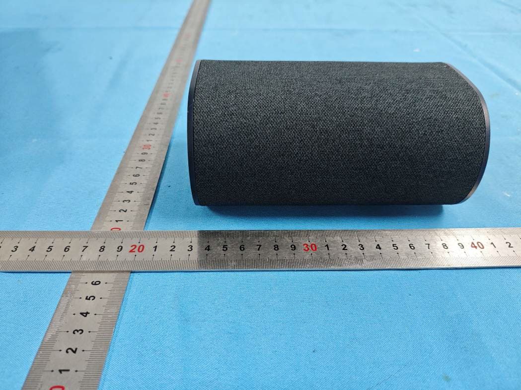
HBOSB2686SU
Aug 20, 20265.1.2 Channel Surround Soundbar
Equipment Class
DTS - Digital Transmission System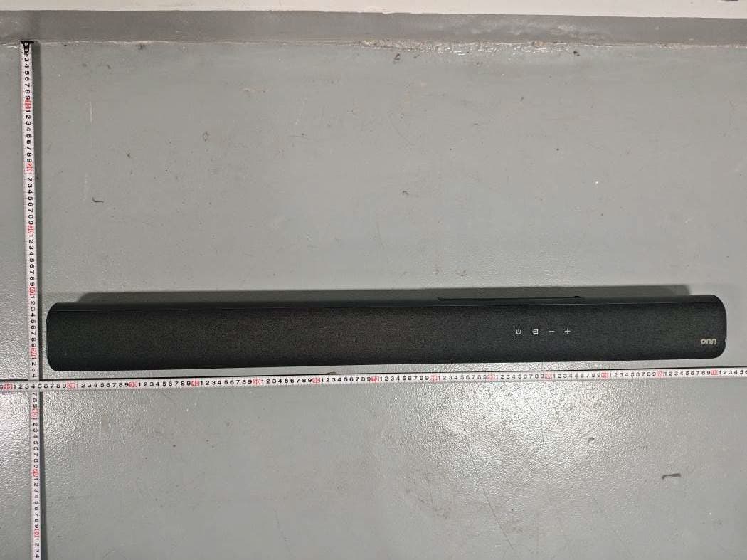
HBOSB2686
Aug 20, 20265.1.2 Channel Surround Soundbar
Equipment Class
DTS - Digital Transmission System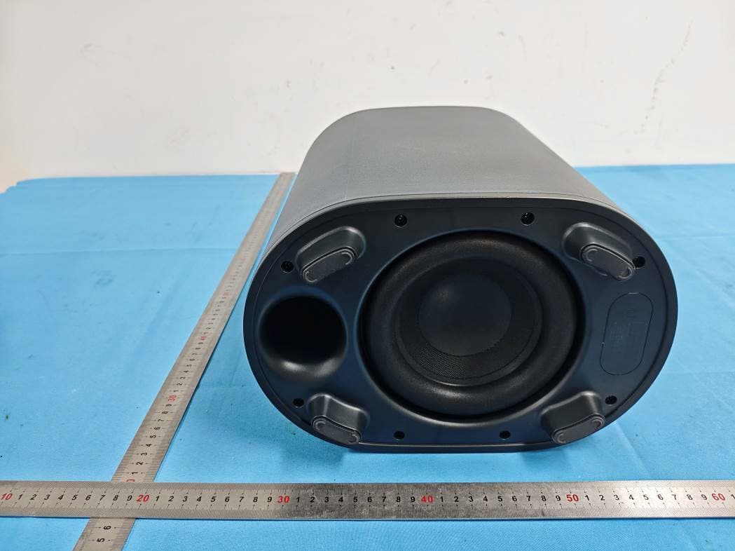
HBOSB2686SW
Aug 20, 20265.1.2 Channel Surround Soundbar
Equipment Class
DTS - Digital Transmission SystemHBOSB2635DDG
Aug 07, 2026Wireless Dongle
Equipment Class
DSS - Part 15 Spread Spectrum TransmitterHBOSB2635DSU
Aug 07, 20262.1ch Standalone Rear Surround Speakers
Equipment Class
DSS - Part 15 Spread Spectrum Transmitter