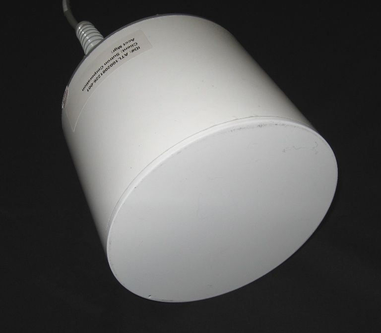
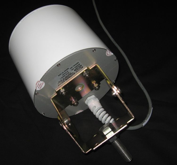
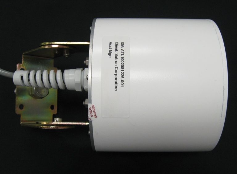
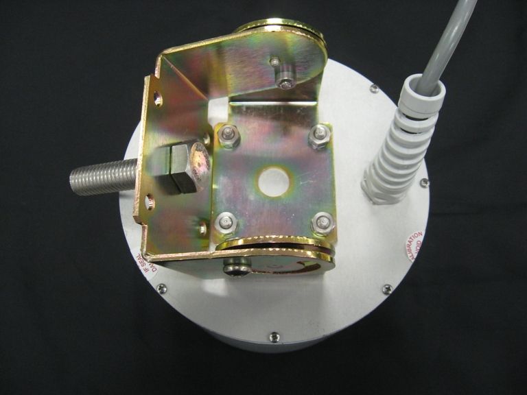
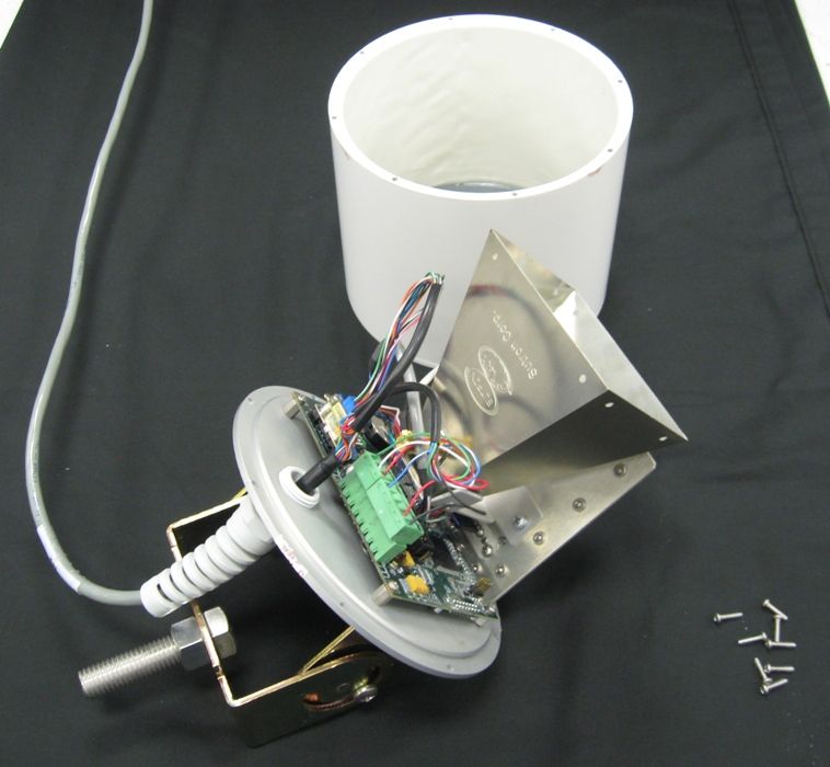
HDBRLR-0003-1Downward pointing Water level sensor
Sutron Corporation
Click to zoom
Application Details
- Equipment Class
- WBT - Wideband Transmitter
- Date of Grant
- Jun 10, 2010
- Application Purpose
- Original Equipment
- Date of Application
- Mar 24, 2010
- Equipment Note
- Downward pointing Water level sensor
- Frequency Range
- 6164.00000000 - 7134.00000000
- Company
- Sutron Corporation
- Country
- United States
Documents & Files
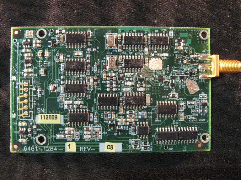
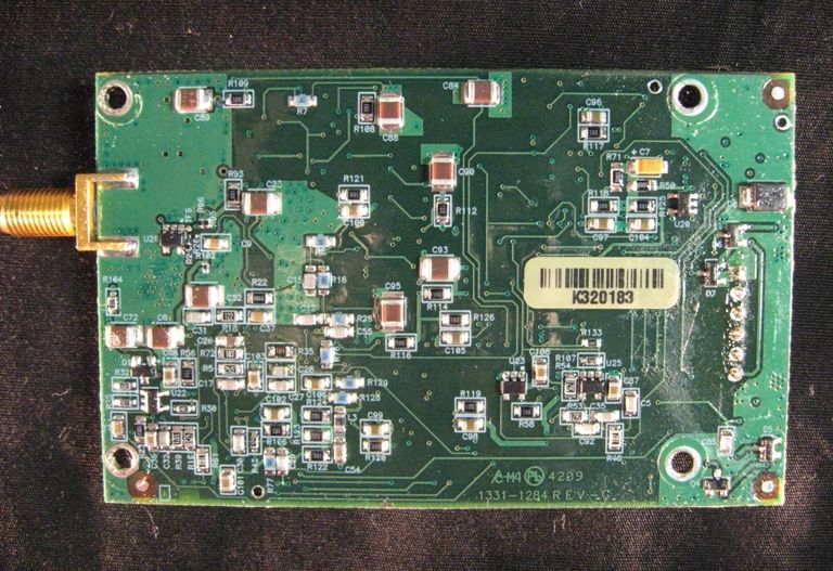
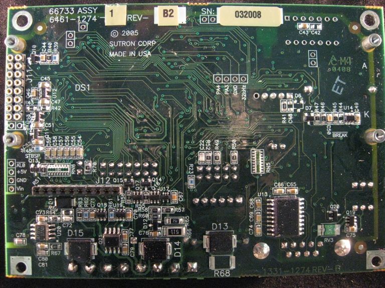
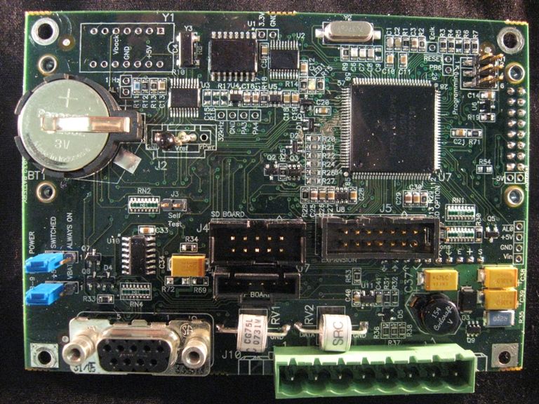
Document Text
Text extracted from the exhibit documents filed with the FCC. Open a document above to read the original.
Users Manual
Radar Level Recorder RLR-0001-1 RLR-0003-1 Operations & Maintenance Manual Part No. 8800-1169 Revision – 1.31 Mar 11th, 2010 Bringing the Benefits of Real-Time Data Collection to the World 2 Bringing the Benefits of Real-Time Data Collection to the World 3 INTRODUCTION ............................................................................................................................................ 6 FEATURES ....................................................................................................................................................... 7 UNPACKING ................................................................................................................................................... 8 CABLING ......................................................................................................................................................... 9 RLR-0003-1 ................................................................................................................................................... 9 TERMINAL BLOCK – RLR-0001-1 ................................................................................................................... 9 Power Connections .................................................................................................................................... 9 SDI-12 Connections ................................................................................................................................. 10 DB9 CONNECTOR ......................................................................................................................................... 10 QUICK INSTALL .......................................................................................................................................... 11 STANDALONE QUICK INSTALL ...................................................................................................................... 11 QUICK INSTALL WITH A LOGGER ................................................................................................................... 11 Redundant Data Collection...................................................................................................................... 12 SETUP AND OPERATION .......................................................................................................................... 13 OVERVIEW .................................................................................................................................................... 13 STARTING THE RADAR ................................................................................................................................... 13 STAGE, DISTANCE TO WATER, AND MEASUREMENT POINT .......................................................................... 14 SETTING STAGE............................................................................................................................................. 14 MEASURING STAGE ....................................................................................................................................... 15 Signal Strength ......................................................................................................................................... 15 Stage Details ............................................................................................................................................ 15 Stage Units ............................................................................................................................................... 15 Right Digits .............................................................................................................................................. 15 Automeasure ............................................................................................................................................ 16 Operating Modes ..................................................................................................................................... 16 Averaging Time ........................................................................................................................................ 17 Averaging ................................................................................................................................................. 17 DQAP ....................................................................................................................................................... 17 Sample Form Period ................................................................................................................................ 17 LAST AUTOMEASURED ................................................................................................................................. 18 DISCHARGE ................................................................................................................................................... 18 LOGGING ....................................................................................................................................................... 18 Events ....................................................................................................................................................... 19 Logged Measurement Time ...................................................................................................................... 19 Log Daily Values ..................................................................................................................................... 19 SETUP ........................................................................................................................................................... 19 CONNECTING RADAR TO A LOGGER .............................................................................................................. 19 Satlink and Radar ......…
Text truncated - open the document above for the full version.
Cover Letter(s)
SUTRON CORPORATION 22400 Davis Drive Sterling, VA 20164 (703) 406-2800 (703) 406-2801 fax www.sutron.com Attention: 22 March 2010 Application Examiner Re: Request for confidentiality Applicant: Sutron Corporation FCC ID: HDBRLR-0003-1 To whom it may concern, Permanent Confidentiality Request is hereby submitted by Sutron Corporation to withhold permanently from public review certain portions of the application for equipment certification for the referenced FCC identifiers. This request for confidentiality is made pursuant to 47 CFR 0.457(d) and 0.459 of the FCC Rules. In particular, the following sections of the application are to be kept permanently confidential: Schematics Detailed Block diagrams Detailed Operational/Functional Description August 4 th 2008 letter from the FCC Short-term Confidentiality Request is hereby submitted by Sutron Corporation to withhold from public review for a period of 45 days from the date of the Grant of Equipment Authorization and prior to marketing, certain portions of the application for equipment certification for the referenced FCC identifiers. This request for confidentiality is made pursuant to 47 CFR 0.457(d) and 0.459 of the FCC Rules. In particular, the following sections of the application are to be kept confidential for a period of 45 days from the date of Authorization: Internal photos Rationale for request for confidentiality: Sutron Corporation has invested considerable time and materials in research and development to produce the referenced product. [Permanent confidentiality: Disclosure of the permanently confidential portions of this application to competitors would not only give them significant competitive advantages in developing similar products, but would also disclose successful implementation of unpublished, leading edge technology developed by us or though licensed technology.] [Short term confidentiality: Disclosure of the short-term confidential portions of this application during the period of importation and/or distribution would reveal key aspects of proprietary technology to competitors and diminish the value of our investment in research and development.] Sutron does not request a final ruling on confidentiality at this time. We ask only that the Commission refrain from posting the above materials on its website, and defer further action pursuant to Section 0.459(d)(3), unless and until the Commission receives a properly framed request for inspection of the materials. The fee for confidentiality has been submitted along with the fee for certification. If you have questions or need further information, please contact the undersigned. Sincerely, Daniel W. Farrell Vice President R&D Sutron Corporation
ID Label/Location Info
SUTRON CORPORATION 22400 Davis Drive Sterling, VA 20164 (703) 406-2800 (703) 406-2801 fax www.sutron.com This label is printed on the following weatherproof (-70 to 110 deg C) Brady label material. BRADYBONDZ™B-480 THERMAL TRANSFER PRINTABLE METALLIC APPEARING, NON-METAL POLYESTER LABEL STOCK WITH RUBBER BASED ADHESIVE
Test Report
Client: Product Designation: RLR-0003-1 Report Number: 100030468ATL-001 All services undertaken are subject to the following general policy: This report is for the exclusive use of Intertek's Client and is provided pursuant to the agreement between Intertek and its Client. Intertek's responsibility and liability are limited to the terms and conditions of the agreement. Intertek assumes no liability to any party, other than to the Client in accordance with the agreement, for any loss, expense or damage occasioned by the use of this report. Only the Client is authorized to copy or distribute this report and then only in its entirety. Any use of the Intertek name or one of its marks for the sale or advertisement of the tested material, product or service must first be approved in writing by Intertek. The observations and test results in this report are relevant only to the sample tested. This report by itself does not imply that the material, product, or service is or has ever been under an Intertek certification program. This report must not be used to claim product endorsement by A2LA, NIST, or any agency of the US Government. Tested by: Tests performed by:Report reviewed by: Standard: Richard C. Bianco EMC Project Engineer Jeremy O. Pickens EMC Department Manager Sutron Cor poration 22400 Davis Drive Sterling, VA 20164 Contact: Chris Buchner Phone: 703.406.2800 TEST REPORT March 9, 2010 Intertek Testing Services NA Inc. 1950 Evergreen Blvd., Suite 100 Duluth, GA 30096 FCC Part 15.250 - Operation of wideband systems within the band 5925 to 7250 MHz Page 1 of 28EMC Report for Sutron Corporation on the RLR-0003-1 03/09/2010Report Number: 100030468ATL-001Issued: Intertek 2.0 Test Summary 1.0 Introduction and Conclusion Test DateTest Full NameResultSection System setup including cable interconnection details, support equipment and simplified block diagram. (System Setup)4.0 02/23/201015.250(a) and 15.250(b): -10 dB Bandwidth requireqments (Bandwidth)PASS5.0 02/24/201015.250(d)(1) Radiated power (EIRP) density (EIRP power density)PASS6.0 02/23/2010Peak Power in a 50 MHz bandwidth (Peak Power per 50 MHz)PASS7.0 02/23/2010Radiated emissions below 960 MHz (Radiated Emissions (<960 MHz))PASS8.0 02/23/201015.250(d)(2) Radiated power (EIRP) density in GPS receive bands (EIRP power density (GPS))PASS9.0 The tests indicated in section 2.0 were performed on the product constructed as described in section 3.0. The remaining test sections are the verbatum text from the actual data sheets used during the investigation. These test sections include the test name, the specified test Method, a list of the actual Test Equipment Used, documentation Photos, Results and raw Data. No additions, deviations, or exclusions have been made from the standard(s) unless specifically noted. Based on the results of our investigation, we have concluded the product tested complies with the requirements of the standard(s) indicated. The results obtained in this test report pertain only to the item(s) tested. Page 2 of 28EMC Report for Sutron Corporation on the RLR-0003-1 03/09/2010Report Number: 100030468ATL-001Issued: Intertek 3.0 Description of Equipment Under Test Equipment Under Test Description Manufacturer Model Number Serial Number Radar Level Recorder Sutron RLR-0003-1 NA EUT receive date: 02/18/2010 EUT receive condition: Good Description of EUT provided by Client: A Precision water level measuring instrument using radar pulses to measure levels without direct contact with water, the RLR can be located on a bridge, pier or any structure over the water’s surface. Description of EUT exercising: The EUT was placed in a continuous transmit state during testing. Page 3 of 28EMC Report for Sutron Corporation on the RLR-0003-1 03/09/2010Report Number: 100030468ATL-001Issued: Intertek System setup including cable interconnection details, support equipment and simplified block diagram. (System Setup) 4.0 Method: Record the details of EUTcabling, document the support equipment, and show the interconnections in a block diagram. EUT AC Mains BatteryLaptop Simplified Block Diagram Drawing: Page 4 of 28EMC Report for Sutron Corporation on the RLR-0003-1 03/09/2010Report Number: 100030468ATL-001Issued: Intertek System setup including cable interconnection details, support equipment and simplified block diagram. (System Setup) 4.0 A LaptopDellClient equipmentClient equipment BatteryWerkerWKA12-80C/FRK40401A Support Equipment DescriptionManufacturerModel NumberSerial Number EUTBattery/Laptop supportRS23210mNoNo Description EUT Cabling Connection Length Shielding FerritesIDFromTo Data: Page 5 of 28EMC Report for Sutron Corporation on the RLR-0003-1 03/09/2010Report Number: 100030468ATL-001Issued: Intertek 15.250(a) and 15.250(b): -10 dB Bandwidth requireqments (Bandwidth)5.0 Method: The -10 dB bandwidth of a device operating under the provisions of this section must be contained within the 5925-7250 MHz band under all conditions of operation including the effects from stepped frequency, frequency hopping or other modulation techniques that may be employed as well as the frequency stability of the transmitter over expected variations in temperature and supply voltage. The -10 dB bandwidth of the fundamental emission shall be at least 50 MHz. For transmitters that employ frequency hopping, stepped frequency or similar modulation types, measurement of the -10 dB minimum bandwidth specified in this paragraph shall be made with the frequency hop or step function disabled and with the transmitter operating continuously at a fundamental frequency following the provisions of §15.31(m). The -10 dB bandwidth is based on measurement using a peak detector, a 1 MHz resolution bandwidth, and a video bandwidth greater than or equal to the resolution bandwidth. Description:Manufacturer:Model:Asset Number:Cal Date:Cal Due: Test Equipment Used: Antenna, Horn, <18 GHzEMCO311521306104/30/200904/30/2010 Cable, 7 meters, 1-18GHzStorm Products Co.PR90-241-7M…
Text truncated - open the document above for the full version.
Contact Information
Applicant
Daniel W. Farrell(VP R&D)
Test Firm
Intertek Testing Services NA Inc.Charles Parker
Technical Specifications
| # | Rule Parts | Frequency Range | Power Output |
|---|---|---|---|
| 1 | 15.250 | 6.16 GHz - 7.13 GHz | - |
Other Applications from Sutron Corporation

HDB-6461-1311-1
Oct 06, 20142.4GHz HP RF Stamp Module
Equipment Class
DTS - Digital Transmission System