HLZMS2130BGNotebook Computer with WLAN
Acer Incorporated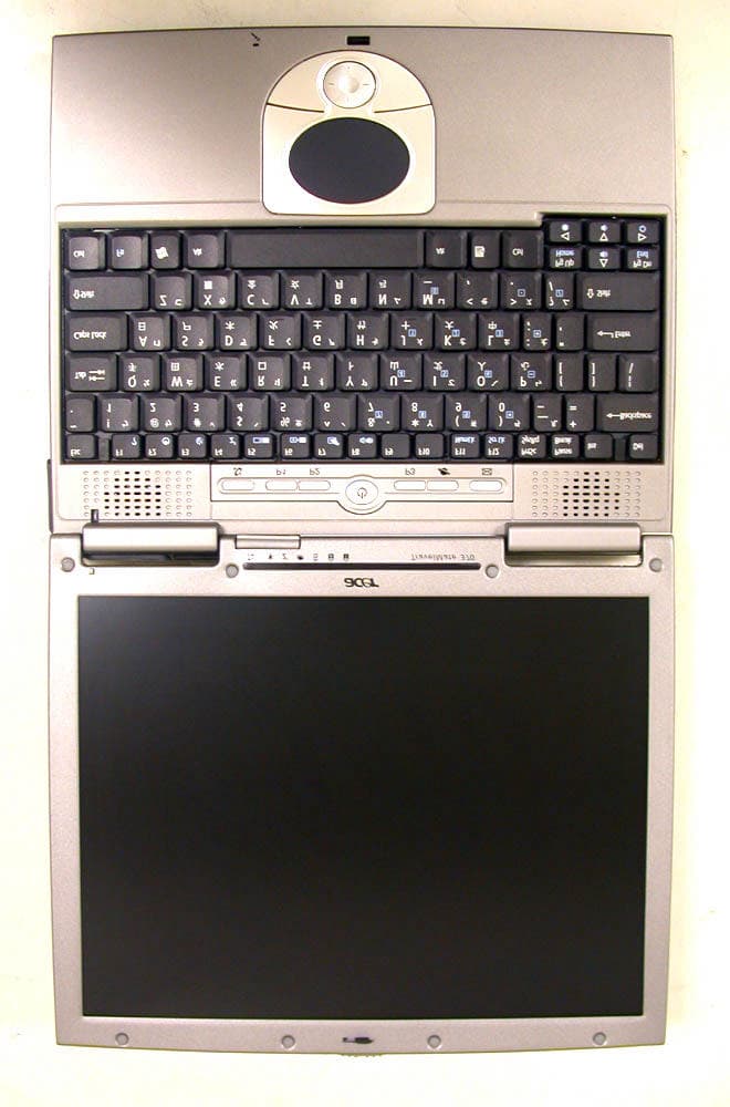
Click to zoom
Application Details
- Equipment Class
- DTS - Digital Transmission System
- Date of Grant
- Jul 28, 2004
- Application Purpose
- Original Equipment
- Date of Application
- Jul 28, 2004
- Equipment Note
- Notebook Computer with WLAN
- Frequency Range
- 2412.00000000 - 2462.00000000
- Company
- Acer Incorporated
- Country
- Taiwan
Documents & Files
Document Text
Text extracted from the exhibit documents filed with the FCC. Open a document above to read the original.
Users Manual
TravelMate 370 series MS2130 User’s guide Changes may be made periodically to the information in this publication without obligation to notify any person of such revision or changes. Such changes will be incorporated in new editions of this manual or supplementary documents and publications. This company makes no representations or warranties, either expressed or implied, with respect to the contents hereof and specifically disclaims the implied warranties of merchantability or fitness for a particular purpose. Record the model number, serial number, purchase date, and place of purchase information in the space provided below. The serial number and model number are recorded on the label affixed to your computer. All correspondence concerning your unit should include the serial number, model number, and purchase information. No part of this publication may be reproduced, stored in a retrieval system, or transmitted, in any form or by any means, electronic, mechanical, photocopy, recording, or otherwise, without the prior written permission of Acer Incorporated. Model number : _________________________________ Serial number: ___________________________________ Purchase date: ___________________________________ Place of purchase: ________________________________ Copyright © 2003 Acer Incorporated. All Rights Reserved. TravelMate 370 series User’s guide Original Issue: September 2003 TravelMate 370 series Notebook computer Acer and the Acer logo are registered trademarks of Acer Incorporated. Other company's product names or trademarks are used herein for identification purposes only and belong to their respective companies. iii English First things first We would like to thank you for making the TravelMate series of notebook computers your choice for your mobile computing needs. We hope you will be happy with your TravelMate as much as we enjoyed making it for you. Yo u r g u i d e s To help you use your TravelMate, we have designed a set of guides: For more information about our products, services, and support information, please visit our Web site (www.acer.com). First off, the Just for Starters... poster helps you get started with setting up your computer. This User’s guide introduces you to the many ways your computer can help you be more productive. This guide provides clear and concise information about the computer, so read it thoroughly. If you ever need to print out a copy, this User’s guide is also available in PDF (Portable Document Format). Follow these steps: 1 Click on Start, All Programs, AcerSystem. 2 Click on AcerSystem User’s guide. Note: Viewing the file requires Adobe Acrobat Reader installed. For instructions on how to use Adobe Acrobat Reader, access the Help menu. iv English Basic care and tips for using your computer Turning your computer on and off To turn on the computer, simply press the power button on the left of the launch keys found above your TravelMate’s standard keyboard. See “Front open view” on page 3 for the location of the power button. To turn the power off, do any of the following: •Use the Windows shutdown command For Windows 2000: Click on Start, Shut Down..., and select Shut down; then click on OK. - or - For Windows XP: Click on Start, Turn off Computer; then click Tur n Off. •Use the power button Note: You can also use the power button to perform power management functions. See Windows help for more information. •Use the customized functions for power management You can also shut down the computer by closing the display cover, or by pressing the sleep hot key (Fn-F4). See the online guide for details. Note: If you cannot power off the computer normally, press and hold the power button for more than four seconds to shut down the computer. If you turn off the computer and want to turn it on again, wait at least two seconds before powering up. Taking care of your computer Your computer will serve you well if you take care of it. •Do not expose the computer to direct sunlight. Do not place it near sources of heat, such as a radiator. •Do not expose the computer to temperatures below 0ºC (32ºF) or above 50ºC (122ºF). •Do not subject the computer to magnetic fields. v English •Do not expose the computer to rain or moisture. •Do not spill water or any liquid on the computer. •Do not subject the computer to heavy shock and vibration. •Do not expose the computer to dust and dirt. •Never place objects on top of the computer to avoid damaging the computer. •Do not slam the computer display when you close it. •Never place the computer on uneven surfaces. Taking care of your AC adapter Here are some ways to take care of your AC adapter: •Do not connect the adapter to any other device. •Do not step on the power cord or place heavy objects on top of it. Carefully route the power cord and any cables away from personal traffic. •When unplugging the power cord, do not pull on the cord itself but pull on the plug. •The total ampere ratings of the equipment plugged in should not exceed the ampere rating of the cord if you are using an extension cord. Also, the total current rating of all equipment plugged into a single wall outlet should not exceed the fuse rating. Taking care of your battery pack Here are some ways to take care of your battery pack: •Use only batteries of the same kind as replacements. Turn the power off before removing or replacing batteries. •Do not tamper with batteries. Keep them away from children. •Dispose of used batteries according to local regulations. Recycle if at all possible. vi English Cleaning and servicing •When cleaning the computer, follow these steps: •Power off the computer and remove the battery pack. •Disconnect the AC adapter. •Use a soft cloth moistened with water. Do not use liquid or aerosol cleaners. •To clean the display screen, use an LCD cleaning kit. If any of the following occurs: •The computer has been dropped or the body has been damaged. •Liquid has been spilled into the product. •The computer does not operate nor…
Text truncated - open the document above for the full version.
Users Manual
43 English Installing memory Follow these steps to install memory: 1Turn off the computer, unplug the AC adapter (if connected) and remove the battery pack. Then turn the computer over to access its base. 2Remove the screws from the memory cover (a); then lift up and remove the memory cover (b). 3Insert the memory module diagonally into the slot (1), then gently press it down (2) until it clicks into place. 4Replace the memory cover and secure it with the screw. 5Reinstall the battery pack, and reconnect the AC adapter. 6Turn on the computer. The computer automatically detects and reconfigures the total memory size. 2 Customizing my computer44 English Using system utilities Notebook Manager The computer has a built-in system setup program called Notebook Manager. The Windows-based Notebook Manager allows you to set passwords, the startup sequence of the drives, and power management settings. It also shows current hardware configurations. To start the Notebook Manager, press Fn-F2 or follow these steps: 1Click on Start, All Programs, then Notebook Manager. 2Select the Notebook Manager application to run the program. Click on Help for more information. 45 English Launch Manager Launch Manager allows you to set the two launch keys located above the keyboard. See “Launch Keys” on page 21 for the location of the launch key. You can access the Launch Manager by clicking on Start, All Programs, and then Launch Manager to start the application. BIOS Utility The BIOS Utility is a hardware configuration program built into your computer’s BIOS (basic input/output system). Your computer is already properly configured and optimized, and you do not need to run this utility. However, if you encounter configuration problems, you may need to run it. To activate the BIOS Utility, press F2 during the POST (power-on self-test) while the TravelMate logo is being displayed. 2 Customizing my computer46 English Disk to Disk Recovery Disk to Disk Recovery allows you to restore the hard drive with the original software content that was installed when you purchased your notebook. Follow the steps below to access Disk to Disk Recovery. It is important to back up all data files before you use this option because your drive will be reformatted and all data will be erased. Restoring process: 1Press F2 to enter BIOS setup during Power-On Self-Test (POST while the TravelMate logo is being displayed). 2Select “Advanced”. 3Refer to the on-screen instruction to set the Boot From D2D mode to “Enabled” and exit. 4Promptly press F10 to enter on-screen instructions to continue the process. After restarting your computer, the Windows installation continues. 3 Troubleshooting my computer This chapter instructs you on how to deal with common system problems. Read it before calling a technician if a problem occurs. Solutions to more serious problems require opening up the computer. Do not attempt to open the computer by yourself. Contact your dealer or an authorized service center for assistance. Key link: www.acersupport.com 49 English Frequently-asked questions The following is a list of possible situations that may arise during the use of your computer. Easy answers and solutions are provided for each one. I pressed the power button and opened the display, but the computer does not start or boot-up. Look at the Power indicator: •If it is not lit, no power is being applied to the computer. Check the following: •If you are running on battery power, it may be low and unable to power the computer. Connect the AC adapter to recharge the battery pack. •Make sure that the AC adapter is plugged in properly to the computer and to the power outlet. •If it is lit, check the following: •Is a non-bootable (non-system) diskette in the external USB floppy drive? Remove or replace it with a system diskette and press Ctrl-Alt-Del to restart the system. Nothing appears on the screen. The computer’s power management system automatically blanks the screen to save power. Press any key to turn the display back on. If pressing a key does not turn the display back on, two things might be the cause: •The brightness level might be too low. Press Fn-↑ (increase) to adjust the brightness level. •The display device might be set to an external monitor. Press the display toggle hot key Fn-F5 to toggle the display back to the computer. •If the Sleep indicator is lit, the computer is in Sleep mode. Press and release the power button to resume. Image is not full-screen. The computer display has a native resolution of 1024 x 768 (XGA) for the 12.1”. If you set the resolution lower than this, the screen expands 3 Troubleshooting my computer50 English to fill the computer display. Right-click on your Windows desktop and select Properties to bring up the Display Properties dialog box. Then click on the Settings tab to make sure that the resolution is set to the appropriate resolution. Resolutions lower than the specified resolution are not full-screen on the computer or on an external monitor. No audio is heard from the computer. Check the following: •The volume may be muted. In Windows, look at the volume control (speaker) icon on the taskbar. If it is crossed-out, click on the icon and deselect the Mute option. •The volume level may be too low. In Windows, look at the volume control icon on the taskbar. You can also use the volume control buttons to adjust the volume. See “Keyboard Hot keys” on page 17 for more detail. •If headphones, earphones or external speaker are connected to the line-out port on the computer’s left panel, the internal speaker automatically turn off. I want to eject the optical drive tray without turning on the power. I cannot eject the optical drive tray. There is a mechanical eject button on the optical drive. Simply insert the tip of a pen or paperclip and push to eject the tray. The keyboard does not respond. Try attaching an external keyboard to the USB 2.0 connector on the r ight or left of the computer. If it works, contact your deale…
Text truncated - open the document above for the full version.
Users Manual
User’s Guide PRO/Wireless 2200BG Network Connection Model WM3B2200BG Intel(R) PRO/Wireless 2200BG User's Guide Your Intel(R) PRO/Wireless 2200BG Network Connection adapter works with either 802.11b or 802.11g wireless standard. Operating at 2.4 GHz frequency at speeds of up to 54 Mbps you can now connect your computer to high-capacity existing 802.11b networks using multiple access points within large or small environments, and also to high-speed 802.11g networks. Your wireless adapter maintains automatic data rate control according to access point location to achieve the fastest possible connection. All your wireless client connections can be easily managed by the Intel(R) PROSet for Wireless utility. Using the PROSet Profile Wizard, you can create profiles automatically to suite your specific connection requirements. Enhanced security measures using 802.1x, WPA encryption and authentication, and 128-bit WEP encryption is standard for both 802.11b and 802.11g. Introduction to Wireless Networking Software Installation Using Intel(R) PROSet Connecting to a Network Security Overview Setting Up Security Troubleshooting Specifications Glossary Customer Support Safety and Regulatory Notices Warranty Adapter Registration Information in this document is subject to change without notice. (c) 2000–2003 Intel Corporation. All rights reserved. Intel Corporation, 5200 N.E. Elam Young Parkway, Hillsboro, OR 97124-6497 USA The copying or reproducing of any material in this document in any manner whatsoever without the written permission of Intel Corporation is strictly forbidden. Intel(R) is a trademark or registered trademark of Intel Corporation or its subsidiaries in the United States and other countries. Other trademarks and trade names may be used in this document to refer to either the entities claiming the marks and names or their products. Intel disclaims any proprietary interest in trademarks and trade names other than its own. Microsoft and Windows are registered trademarks of Microsoft Corporation. *Other names and brands may be claimed as the property of others. Intel Corporation assumes no responsibility for errors or omissions in this document. Nor does Intel make any commitment to update the information contained herein. September 2003 Back to Contents Page Wireless LAN Overview: Intel(R) PRO/Wireless 2200BG User's Guide About Wireless LAN Technology l Choosing a WLAN l Configuring a WLAN l Identifying a WLAN l Surveying the Site of Your WLAN l Factors Affecting Range A wireless network connects computers without using network cables. Computers use radio communications to send data between each other. You can communicate directly with other wireless computers, or connect to an existing network through a wireless access point. When you set up your wireless adapter, you select the operating mode for the kind of wireless network you want. You can use your wireless adapter to connect to other similar wireless devices that comply with the 802.11 standard for wireless networking. Choosing a Wireless LAN Wireless LANs can operate with or without access points, depending on the number of users in the network. Infrastructure mode uses access points to allow wireless computers to send and receive information. Wireless computers transmit to the access point, the access point receives the information and rebroadcasts it to other computers. The access point can also connect to a wired network or to the Internet. Multiple access points can work together to provide coverage over a wide area. Peer-to-Peer mode, also called Ad Hoc mode, works without access points and allows wireless computers to send information directly to other wireless computers. Ad Hoc Mode is only supported in 802.11b and 802.11g networks. You can use Peer-to-Peer mode to network computers in a home or small office or to set up a temporary wireless network for a meeting. Configuring a Wireless LAN There are three basic components that must be configured for an 802.11 wireless LAN to operate properly: l Network Name: Each wireless network uses a unique Network Name to identify the network. This name is called the Service Set Identifier (SSID). When you set up your wireless adapter, you specify the SSID. If you want to connect to an existing network, you must use the name for that network. If you are setting up your own network you can make up your own name and use it on each computer. The name can be up to 32 characters long and contain letters and numbers. l Profiles: When you set up your computer to access a wireless network, the wireless client manager creates a profile for the wireless settings that you specify. If you want to connect to another network, you can scan for existing networks and make a temporary connection, or create a new profile for that network. After you create profiles, your computer will automatically connect when you change locations. l Security: The 802.11 wireless networks use encryption to help protect your data. Wired equivalent privacy (WEP) uses a 64-bit or 128-bit shared encryption key to scramble data. Before a computer transmits data, it scrambles the data using the secret encryption key. The receiving computer uses this same key to unscramble the data. If you are connecting to an existing network, use the encryption key provided by the administrator of the wireless network. If you are setting up your own network you can make up your own key and use it on each computer. m Wi-Fi Protected Access (WPA) is a security enhancement that strongly increases the level of data protection and access control to a WLAN. WPA mode enforces 802.1x authentication and key-exchange to strengthen data encryption. WPA utilizes its Temporal Key Integrity Protocol (TKIP). TKIP provides important data encryption enhancements that include a per-packet key mixing function, a message integrity check (MIC) named "Michael", an extended initialization vector (IV) with sequencing rules, and a also re-keying mechanism. Using thes…
Text truncated - open the document above for the full version.
Users Manual
71 English Canada - Industry Canada (IC) •This device complies with RSS 210 of Industry Canada. Europe - EU Declaration of Conformity This device complies with the standards listed below, following the provisions of the EMC Directive 89/336/EEC: •ETSI EN 301 489-1/17 •ETSI EN 300 328-2 •EN 300 328 V1.4.1. USA - Federal Communications Commission (FCC) This device complies with Part 15 of FCC Rules. Operation of the devices in an Wireless LAN System is subject to the following two conditions: •This device may not cause harmful interference. •This device must accept any interference that may cause undesired operation. Exposure to Radio Frequency Radiation The radiated output power of the Wireless module is far below the FCC radio frequency exposure limits. Nevertheless, the Wireless module shall be used in such a manner that the potential for human contact during normal operation is minimized. The transmitter and the antenna are permanently installed inside the notebook, and are specific for this model (not for generic computer). The antenna of this device is installed near the bottom of the LCD display. This equipment complies with FCC radiation exposure limits set forth for an uncontrolled environment. End users must follow the specific operation instruction for satisfying RF exposure compliance. This transmitter must not be co-located or operating in conjunction with any other antenna or transmitter. This equipment has been tested and found to comply with the limits for a Class B digital device, pursuant to Part 15 of the FCC Rules. These
Cover Letter(s)
No. 65, Ku Dai Keng St., Hsichih, Taipei 221, R.O. C. Tel: 886-2-2646-2550 FAX: 886-2-26464641 No. 120, Lane 180, San Ho Tsuen, Hsin Ho Rd. Lung-Tan Hsiang, Tao Yuan County 325, Taiwan, R.O.C. Tel: 886-3-407-1718 FAX:886-3-407-1738 Rev 2 C:\tmp\04LR028 MS2130(SkylarkII)\FCC\AP FORM.doc 02/08/02 Request for Confidentiality Date:Jul. 21, 2004 American Telecommunications Certification Body, Inc. 6731 Whittier Avenue Suite C110 McLean, VA 22101 RE: Certification Application FCC ID: HLZMS2130BG Please be advised that the following information is to be held confidential on behalf of Acer Inc. : q Block Diagram q Schematics q Technical Spec The application contains technical information which Acer Inc. deems to be trade secrets and proprietary. If made public, the information might be used to the disadvantage of the applicant in the market place. Thank you for your attention to this matter. Sincerely, ___________________________ Eddy Hsiung / Director International Standards Laoboratory
Cover Letter(s)
Acer Incorporated 8F, 88, Sec. 1, Hsin Tai Wu Rd., Hsichih Taipei Hsien 221, Taiwan, R.O.C. Tel : 886-2-2696-1234 Fax : 886-2-2696-3535 www.acer.com Letter Of Agency Date:Jul. 21, 2004 American Telecommunications Certification Body, Inc. 6731 Whittier Avenue Suite C110 McLean, VA 22101 To Whom It May Concern: Please be advised that Acer Incorporated authorizes International Standards Laboratory (ISL) to act on our behalf, until otherwise notified, for applications submitted to American Telecommunications Certification Body, Inc. (ATCB). We certify that we are not subject to denial of federal benefits that includes FCC benefits, pursuant to Section 5301 of the Anti-Drug Abuse ACT of 1988, U.S.C. 862. Further, no party as defined in 47 CFR 1.2002(b), for this application is subject to denial of federal benefits that includes FCC benefits. Thank you for your attention to this matter. ________________ Easy Lai / Director Acer Incorporated
Cover Letter(s)
American Telecommunications Certification Body Inc. 6731 Whittier Ave, McLean, VA 22101 July 22, 2004 RE: FCC ID: HLZMS2130BG_ATCB001514 Attention: Daphne Liu I have a few comments on this Application. Please note that further comments may arise in response to answers provided to the questions below. 1. Please note that the block diagram of the transmitter provided does not address the requirements of 2.1033(b)(5) which states, “A block diagram showing the frequency of all oscillators in the device. The signal path and frequency shall be indicated at each block. The tuning range(s) and intermediate frequency(ies) shall be indicated at each block. A schematic diagram is also required for intentional radiators.” Please provide a block diagram in accordance with the requirements of 2.1033(b)(5). Please also note that you do not need to provide a block diagram or schematics of the computer, only the transmitter. 2. Please note that while the manual on page 29 says the antennae for the transmitter are installed in the top of the LCD, other documentation clearly show the antennae are installed in the bottom of the unit closer than 20 cm to the body (see internal and external photo exhibits). This means that the manual must be changed to include the proper SAR evaluation statements. 3. Please note that as this device power exceed the level at which SAR is required, SAR compliance to the rf exposure requirements of the FCC and IC must be shown. Please provide the necessary SAR report for this device. 4. Please note that while the notes for the radiated emissions tables in the report indicate the analyzer mode (i.e. pk – av –etc) the actual data tables do not provide this information. Please clearly identity the analyzer mode (peak, average or QP) for the data in the tables. Please note that it is not clear if the data taken was peak mode compared to the 54dBuV limit. Please clearly identify the type measurements and that they clearly meet the 54dBuV/m average limits and the 20dB over the average limits (74dBuV/m) where applicable. This applies to both the FCC and RSS210 reports. Industry Canada 5. Please provide the required RSS102 compliance letter. 6. Please provide the required ATCB required RSP100 appendixes I and II. 7. Please provide the required REL acknowledgement attestation letter. Dennis Ward mailto:[email protected] The items indicated above must be submitted before processing can continue on the above referenced application. Failure to provide the requested information may result in application termination. Correspondence should be considered part of the permanent submission and may be viewed from the Internet after a Grant of Equipment Authorization is issued. Please do not respond to this correspondence using the email reply button. In order for your response to be processed expeditiously, you must submit your documents through the AmericanTCB.com website. Also, please note that partial responses increase processing time and should not be submitted. Any questions about the content of this correspondence should be directed to the sender.
Cover Letter(s)
July 29, 2004 RE: FCC ID: HLZMS2130BG_ATCB001514 Dear Dennis, Here are our answers: 1. Please note that the block diagram of the transmitter provided does not address the requirements of 2.1033(b)(5) which states, “A block diagram showing the frequency of all oscillators in the device. The signal path and frequency shall be indicated at each block. The tuning range(s) and intermediate frequency(ies) shall be indicated at each block. A schematic diagram is also required for intentional radiators.” Please provide a block diagram in accordance with the requirements of 2.1033(b)(5). Please also note that you do not need to provide a block diagram or schematics of the computer, only the transmitter. Ans: We have uploaded the modified block diagram. 2. Please note that while the manual on page 29 says the antennae for the transmitter are installed in the top of the LCD, other documentation clearly show the antennae are installed in the bottom of the unit closer than 20 cm to the body (see internal and external photo exhibits). This means that the manual must be changed to include the proper SAR evaluation statements. Ans: We have uploaded the updated users manual P 71. 3. Please note that as this device power exceed the level at which SAR is required, SAR compliance to the rf exposure requirements of the FCC and IC must be shown. Please provide the necessary SAR report for this device. Ans: We have uploaded the SAR report. 4. Please note that while the notes for the radiated emissions tables in the report indicate the analyzer mode (i.e. pk – av –etc) the actual data tables do not provide this information. Please clearly identity the analyzer mode (peak, average or QP) for the data in the tables. Please note that it is not clear if the data taken was peak mode compared to the 54dBuV limit. Please clearly identify the type measurements and that they clearly meet the 54dBuV/m average limits and the 20dB over the average limits (74dBuV/m) where applicable. This applies to both the FCC and RSS210 reports. Ans: We have uploaded the updated report. Industry Canada 5. Please provide the required RSS102 compliance letter. 6. Please provide the required ATCB required RSP100 appendixes I and II. 7. Please provide the required REL acknowledgement attestation letter. Ans: We have uploaded the RSP-100 & REL. Please review the information we submitted. Thanks for your help. Daphne Liu 2004/07/29 ISL
Cover Letter(s)
J1 NoteBook Embedded Antenna Wistron P/NMain/25.90050.001 SmartAnt P/NACR-05011 S/NMain00001 Customer approved By Date Smartant approved By Simon Date06-14-02 Smartant prepared By Eric Date06-14-02 SmartAnt Telecom Co., Ltd SmartAnt Telecom Co.,Ltd. I N D E X NB Embedded Antenna 1. Introduction........................................................1 2. Outline Drawing 2.1 Antenna Placement ................................................ 2 2.2 Antenna Outline Drawing.......................................... 3 2.3 Inspection Resulrs...................................................4 3. Product Specification 3.1 Electrical Specification............................................. 5 3.2 Material Specification............................................... 5 3.3 Environmental Specification.......................................6 4. Antenna Test Methods 4.1 VSWR Test ............................................................7 4.2 Gain & Radiation pattern Test....................................9 4.3 YZ and XZ pattern plan..........................................12 4.4 CPK.....................................................................15 5. Package............................................................16 SmartAnt Telecom Co.,Ltd. Page 1 of 16 1. Introduction ¾ Designed for IEEE 802.11b/802.11a wireless-Lan. The antennas are designed in 2.4~2.5 GHz 15.15~5.35GHz for dual band use. ¾ Special design for Embedded use. General Dimension :32.8*5*5mm, The antennas are special design for this environment. ¾ Ultra-Fine Teflon coaxial cable and connector. I-pex MHF connector with Teflon coaxial Nissei cable φ = 1.13 mm ¾ Space and polarization diversity These 2 antennas are arrayed in different space and polarization to accomplish diversified radiation pattern. SmartAnt Telecom Co.,Ltd. Page 2 of 16 2.Antenna Placement & Outline drawing 2.1 Antenna Placement Antenna Antenna Position SmartAnt Telecomm Co.,Ltd. Page 3 of 16 2.2 Outline drawing SmartAnt Telecomm Co.,Ltd. Page 4 of 16 FAI DATA SHEET Supplier : SmartAnt Date: 2002/6/18 Wistron : Drawing Number:ACR-05011 Part Description: Embedded (left) Antenna Inspected by: Ben Manufacturing Site:ZZZZ Gauge#/Unit: PC-08 (mm) SQM/Alex MH Lai Revision:0 Approved by: Eric Production Line: A Gauge/Unit: (mm) DRAWING SPECIFICATIONS INSPECTION RESULTS INSPECTION ANALYSIS Sample Number Deviation from Nominal % Tolerance Acc/Rej Inspection Precision ITEM LOCATION NOMINAL +TOL -TOL 1 2 3 1 2 3 Mean UPPER LOWER HIGH LOW Method of Gauge 1 32.80 0.20 0.20 32.77 32.78 32.77 -0.03 -0.02 -0.03 32.77 0% 15% 0.01mm 2 160.00 4.00 4.00 160.00 160.00 160.00 0.00 0.00 0.00 160.00 0% 0% 1mm 3 3.00 0.10 0.10 3.05 3.03 3.03 0.05 0.03 0.03 3.04 50% 0% 0.01mm 4 5.50 0.10 0.10 5.52 5.53 5.50 0.02 0.03 0.00 5.52 30% 0% 0.01mm 5 7.50 0.10 0.10 7.45 7.47 7.47 -0.05 -0.03 -0.03 7.46 0% 50% 0.01mm 6 0.40 0.10 0.10 0.40 0.41 0.40 0.00 0.01 0.00 0.40 10% 0% 0.01mm Supplier : SmartAnt Date: 2002/6/18 Wi…
Text truncated - open the document above for the full version.
Contact Information
Applicant
RU Jan(Sr. Manager)
Technical Contact
International Stantards LaboratoryJerry Chiou
[email protected]886-3-407-1718
No. 65, Ku Dai Keng Street, · Hsichih · Taiwan
Test Firm
International Standards LaboratoryDavid Wu
Technical Specifications
| # | Rule Parts | Frequency Range | Power Output |
|---|---|---|---|
| 1 | 15C | 2.41 GHz - 2.46 GHz | 45.00 mW |
Other Applications from Acer Incorporated
HLZA26007
Aug 07, 2026Tablet PC
Equipment Class
DTS - Digital Transmission SystemHLZA26003
Jul 28, 2026Tablet PC
Equipment Class
6XD - 15E 6 GHz Low Power Indoor ClientHLZAMR570
Apr 21, 2026Acer Wireless Mouse
Equipment Class
DTS - Digital Transmission SystemHLZ-NSK510
Apr 09, 2026Gaming sound bar
Equipment Class
DSS - Part 15 Spread Spectrum TransmitterHLZA26002
Apr 01, 2026Tablet PC
Equipment Class
NII - Unlicensed National Information Infrastructure TX