HLZUWA2USB WiFi adapter
Acer Incorporated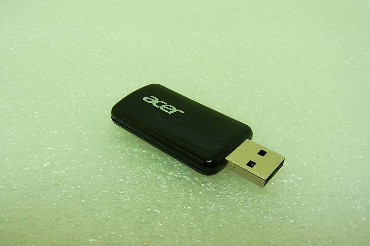
Click to zoom
Application Details
- Equipment Class
- DTS - Digital Transmission System
- Date of Grant
- Apr 18, 2013
- Application Purpose
- Original Equipment
- Date of Application
- Apr 18, 2013
- Equipment Note
- USB WiFi adapter
- Frequency Range
- 5755.00000000 - 5795.00000000
- Company
- Acer Incorporated
- Country
- Taiwan
Documents & Files
Document Text
Text extracted from the exhibit documents filed with the FCC. Open a document above to read the original.
Users Manual
USB WiFi for Projector User’s Manual l Brand:acer Model:UWA2 Rev. 1.01 FCC statement This equipment has been tested and found to comply with the limits for a Class B digital device, pursuant to Part 15 of the FCC Rules. These limits are designed to provide reasonable protection against harmful interference in a residential installation. This equipment generates, uses and can radiate radio frequency energy and, if not installed and used in accordance with the instructions, may cause harmful interference to radio communications. However, there is no guarantee that interference will not occur in a particular installation. If this equipment does cause harmful interference to radio or television reception, which can be determined by turning the equipment off and on, the user is encouraged to try to correct the interference by one of the following measures: * Reorient or relocate the receiving antenna. * Increase the separation between the equipment and receiver. * Connect the equipment into an outlet on a circuit different from that to which the receiver is connected. * Consult the dealer or an experienced radio/TV technician for help. REGULATION INFORMATION The WLAN 11abgn USB WiFi Adapter must be installed and used in strict accordance with the manufacturer’s instructions. This device complies with the following radio frequency and safety standards. This device complies with Part 15 of the FCC Rules. Operation is subject to the following two conditions: (1) This device may not cause harmful interference. (2) This device must accept any interference received, including interference that may cause undesired operation. If the label of the module wouldn’t be visible after integration in a device, the label of the device must include “contains FCC ID: HLZUWA2 IC Statement This Class B digital apparatus complies with Canadian ICES-003 and RSS210 This device complies with Industry Canada licence-exempt RSS standard(s). Operation is subjectto the following two conditions: (1) this device may not cause interference, and (2) this device must accept any interference, including interference that may cause undesired operation of the device. Canada, avis d'Industry Canada (IC): Cet appareil numerique de classe B est conforme aux normes canadiennes ICES-003 et RSS-210.Son fonctionnement est soumis aux deux conditions suivantes : (1) cet appareil ne doit pas causer d'interferences et (2) cet appareil doit accepter toute interference, notamment les interferences qui peuventaffecter son fonctionnement. If the label of the module wouldn’t be visible after integration in a device, the label of the device must include “contains IC: 1754F-UWA2 Si l'étiquette du module ne serait pas visible après l'intégration dans un appareil, l'étiquette del'appareil doit comporter "contient IC: 1754F-UWA2 Under Industry Canada regulations, this radio transmitter may only operate using an antenna of a type and maximum (or lesser) gain approved for the transmitter by Industry Canada. To reduce potential radio interference to other users, the antenna type and its gain should be so chosen that the equivalent isotropically radiated power (e.i.r.p.) is not more than that necessary for successful communication. Conformément à la réglementation d'Industrie Canada, le présent émetteur radio peutfonctionner avec une antenne d'un type et d'un gain maximal (ou inférieur) approuvé pour l'émetteur par Industrie Canada. Dans le but de réduire les risques de brouillage radioélectriqueà l'intention des autres utilisateurs, il faut choisir le type d'antenne et son gain de sorte que lapuissance isotrope rayonnée équivalente (p.i.r.e.) ne dépasse pas l'intensité nécessaire àl'établissement d'une communication satisfaisante. Indoor use only for FCC/IC When suing IEEE 802.11abgn wireless LAN, this product is restricted to indoor use, due to its operation in the 5.15 to 5.25GHz frequency range. The requires this product to be used indoors for the frequency range of 5.15 to 5.25GHz to reduce the potential for harmful interference to co channel mobile satellite systems. RE Exposure information for FCC /IC To comply with FCC /IC exposure requirement for mobile devices this transmitter should only used or installed at projector devices there is less than 20cm separation distance between the antenna and person This Transmitter must not be co-located or operating in conjunction with any other antenna or transmitter. Your device contains a low power transmitter. When device is transmitted it sends out Radio Frequency (RF) signal. Use only with supplied antenna. Unauthorized antenna, modification, or attachments could damage the transmitter and may violate regulations. You are cautioned that changes or modifications not expressly approved by the part responsible for compliance could void the user’s authority to operate the equipment The WIFI USB adapter only use to projector device the USB adapter put in other device is can't drive because the USB adapter is through special software ‘EZ ’ start the WIFI function and the software is use on the projector system only. Europe- R&TTE Compliance Statement Hereby, the company who declares that this equipment complies with the essential requirements and other relevant provisions of DIRECTIVE 1999/5/CE OF THE EUROPEAN PARLIAMENT AND THE COUNCIL of March 9, 1999 on radio equipment and telecommunication terminal Equipment and the mutual recognition of their conformity (R&TTE). The USB WiFi adapter is only for projector . General Description USB WiFi adapter is a power program to project your PC’s screen player to Projector wirelessly. It also brings you extension display function so that you can show different content in the secondary display. From now on, you can upgrade your Projector, or Monitor with WiFi display function in an easy way. Features l Full Screen Mirror Display and Extension Mode Display l Performance and Quality selection l Split Screen support l Support Windows XP~Win8 System Requirements Window…
Text truncated - open the document above for the full version.
Attestation Statements
SCS-F26 Modular Approval Letter Page 4 of 4 Rev 7.0 LMA Declaration Letter We , Acer Incorporated declared that will retain control over the final installation of the device, (FCC ID: HLZUWA2 /IC: 1754F-UWA2 ) such that compliance of the end product is assured. In such cases, an operating condition on the LMA for the module must be only approved for use when installed in devices produced by a specific manufacturer. RU Jan Acer Incorporated 8F, 88, Sec 1, Xintai 5th Rd. Xizhi, New Taipei City ,221,Taiwan R.O.C.
Attestation Statements
Declaration Letter Applicant: Acer Incorporated Product Description: USB WiFi adapter Model: UWA2 The WIFI USB adapter only use to projector device the USB adapter put in other device is can't drive because the USB adapter is through special software ‘EZ ’ start the WIFI function and the software is use on the projector system only. . Sincerely, RU Jan [email protected] Acer Incorporated 8F, 88, Sec 1, Xintai 5th Rd. Xizhi, New Taipei City ,221,Taiwan R.O.C.
Cover Letter(s)
Date: 2013/4/17 To who may concern, I, the undersigned, responsible for the designated person in FCC grant communicator, hereby authorized Ru Jan to sign the FCC application form for certification process. Thank you, Sincerely Yous, Contact Person: Harriot Lee Company Name: Acer Incorporated Company Address: 8F, 88, Sec 1, Xintai 5th Rd. Xizhi, New Taipei City ,221, Taiwan R.O.C.
Cover Letter(s)
SCS-F18: Project and Product Certification Representative Authorization Letter Page 1 of 2 Rev 3.0 775 Montague Expressway Milpitas, CA 95035 Tel: 408-526-1188 Fax: 408-526-1088 Email: [email protected] Project and Product Certification Representative Authorization Letter Reason for Amendment (current / obsolete) Revision History Approved Date From To Initial Release (obsolete) 1.0 1.0 Nov-14-2006 Revised wording (obsolete) 1.0 2.0 Sept–25-2007 Updated company template (current) 2.0 3.0 Jan-31-2012 SCS-F18: Project and Product Certification Representative Authorization Letter Page 2 of 2 Rev 3.0 (Client's Company Letterhead / Logo) (2013/03/26) To: SIEMIC, INC. 775 Montague Expressway, Milpitas, CA 95035 USA Dear Sir/Madam, Re: Project and Product Certification Representative Authorization Letter We, _Acer Incorporated _ hereby authorize SIEMIC, INC. to act as a Certification Body for certifying for the following project(s): Product description: USB WiFi adapter model name: UWA2 We affirm that between SIEMIC and __Acer Incorporated _, any difference in understanding, including test plan, measurement methods, applicable standards and relevant procedures and processes have been resolved prior to commencement of testing activities. Sincerely, RU Jan / Sr. Manager Acer Incorporated 8F, 88, Sec 1, Hsin Tai Wu Rd, Hsichih, New Taipei City 22181, Taiwan, R.O.C.
Cover Letter(s)
SCS-F26 Modular Approval Letter Page 2 of 4 Rev 7.0 (Date) 04/03/2013 (Product name) FCC ID : HLZUWA2 , is seeking FCC Authorization as a Single Modular transmitter / Single Limited Modular Approval (Please check one). The EUT meets the requirements for Single Modular approval / Single Limited Modular Approval (please check one) as detailed in FCC public Notice DA00-1407. Compliance to each of the requirements is described below : Questions are: * Please provide a detailed explanation if the answer is “No.” 1. “The modular transmitter must have its own RF shielding.” Yes / No 2. “The modular transmitter must have buffered modulation/data inputs.” Yes / No 3. “The modular transmitter must have its own power supply regulation.” Yes / No 4. “The modular transmitter must comply with the antenna requirements of section 15.203 and 15.204(c).” Yes / No 5. “The modular transmitter must be tested in a stand-alone configuration.” Yes / No 6. “The modular transmitter must be labeled with its own FCC ID number.” Yes / No 7. “The modular transmitter must comply with any specific rule or operating requirements applicable to the transmitter and the manufacture must provide adequate instruction along with the module to explain any such requirements.” Yes / No 8. “The modular transmitter must comply with any applicable RF exposure requirements.” Yes / No Note: (1) LMA may be granted when one or more of the requirements in the table above cannot be demonstrated. LMA will also be issued in those instances where applicants can demonstrate that they will retain control over the final installation of the device, such that compliance of the end product is assured. In such cases, an operating condition on the LMA for the module must state that the module is only approved for use when installed in devices produced by a specific manufacturer. When LMA is sought, the application for equipment certification must specifically state how control of the end product into which the module will be installed, and will be maintained, such that full compliance of the end product is always ensured. (2) Please provide Clear and specific instructions describing the conditions, limitations and procedures for third-parties to use and/or integrate the module into a host device. (3) For non-Software Defined Radio transmitter modules where software is used to ensure compliance of the device, technical description of how such control is implemented to ensure prevention of third party modification must be provided (see KDB 594280). Note 1: Compliance of a module in its final configuration is the responsibility of the applicant. A host device will not be considered certified if the instructions regarding antenna configuration provided in the original description, of one or more separately certified modules it contains, were not followed. Example: A separately certified low-power transceiver module using Bluetooth technology which is housed in a desktop computer, laptop or peripheral does not require the overall system to be recertified, if the desktop computer, laptop or peripheral, as a stand-alone unit, complies with all applicable technical standards. RU Jan Acer Incorporated 8F, 88, Sec 1, Xintai 5th Rd. Xizhi, New Taipei City ,221,Taiwan R.O.C.
External Photos
FCC ID: HLZUWA2 IC: 1754F-UWA2 International Standards Laboratory Report Number: ISL-13LR039FC APPENDIX 2 PHOTOGRAPHS OF EUT FCC ID: HLZUWA2 IC: 1754F-UWA2 International Standards Laboratory Report Number: ISL-13LR039FC EUT-1. EUT-2.
ID Label/Location Info
FCC ID & IC LABEL FORMAT AND LOCATION Applicant: Acer Incorporated FCC ID: HLZUWA2 IC: 1754F-UWA2
Internal Photos
FCC ID: HLZUWA2 IC: 1754F-UWA2 International Standards Laboratory Report Number: ISL-13LR039FC APPENDIX 3 PHOTOGRAPHS OF EUT FCC ID: HLZUWA2 IC: 1754F-UWA2 International Standards Laboratory Report Number: ISL-13LR039FC EUT-3. EUT-4. FCC ID: HLZUWA2 IC: 1754F-UWA2 International Standards Laboratory Report Number: ISL-13LR039FC EUT-5. WLAN
RF Exposure Info
FCC ID: HLZUWA2 IC: 1754F-UWA2 International Standards Laboratory Report Number: ISL-13LR039FC 12 Maximum Permissible Exposure (MPE) 12.1 Standard Applicable According to 1.1307(b)(1), systems operating under the provisions of this section shall be op- erated in a manner that ensure that the public is not exposed to radio frequency energy level in excess of the Commission’s guideline. This is a Mobile device, the MPE is required. According to 1.1310 and 2.1093 RF exposure is calculated. Limits for Maximum Permissive Exposure (MPE) Frequency Range (MHz) Electric Field Strength (V/m) Magnetic Field Strength (A/m) Power Density (mW/cm 2 ) Averaging Time (minute) Limits for General Population/Uncontrolled Exposure 0.3-1.34 614 1.63 *(100) 30 1.34-30 824/f 2.19/f *(180/f 2 ) 30 30-300 27.5 0.073 0.2 30 300-1500 / / F/1500 30 1500-15000 / / 1.0 30 F = frequency in MHz * = Plane-wave equipment power density FCC ID: HLZUWA2 IC: 1754F-UWA2 International Standards Laboratory Report Number: ISL-13LR039FC 12.2 Maximum Permissible Exposure (MPE) Evaluation The worst case of Average power: refer to section 6.5 for detail measurement date. 802.11b Cable loss = 0 Output Power Limit CH Frequency (MHz) Detector (dBm) PK AV (dBm) (dBm) 1 2412 19.24 16.84 30 6 2437 19.83 17.53 11 2462 19.23 16.92 MPE Prediction (802.11b) Prediction of MPE limit at a given distance Equation from page 18 of OET Bulletin 65, Edition 97-01 S=PG/4R 2 Where: S = Power density P = Power input to antenna G = Power gain of the antenna in the direction of interest relative to an isotropic radiator R = Distance to the center of radiation of the antenna Maximum average output power at antenna input 17.53 (dBm) Maximum Aver age outpu t p ow er at anten na input 56. 6239 28 9 (mW) Duty cycle: 100 (%) Maximu m Pav : 5 6. 62 39 28 9 (mW) Antenna gain (typical): -5.2 (dBi) M aximum an ten na g ain : 0 .3 01 99 51 72 (numeric) Prediction distance: 20 (cm) Prediction frequency: 2437 (MHz) MPE limit f or uncontrolled ex po sure at pred iction 1 (mW/cm2) Power density at predication frequency at 20 (cm) 0.0034037 (mW/cm^2) Measurement Result The predicted power density level at 20 cm is 0.0034037 mW/cm 2 . This is below the uncon- trolled exposure limit of 1 mW/cm 2 at 2437MHz. FCC ID: HLZUWA2 IC: 1754F-UWA2 International Standards Laboratory Report Number: ISL-13LR039FC The worst case of Average power: refer to section 6.5 for detail measurement date. 802.11a_HT20(5G) Channel Frequency (MHz) Output Chain (dBm) Combine Output Power (dBm) Limit(dBm) Chain Achain B AN HT20 149 5745 6.91 11.69 12.94 30 157 5785 7.12 10.52 12.15 30 165 5825 7.11 9.67 11.59 30 MPE Prediction (802.11a) Prediction of MPE limit at a given distance Equation from page 18 of OET Bulletin 65, Edition 97-01 S=PG/4R 2 Where: S = Power density P = Power input to antenna G = Power gain of the antenna in the direction of interest relative to an isotropic radiator R = Distance to the center of radiation of the antenna Maximum average output power at antenna input 12.94 (dBm) Maximum Aver age outpu t p ow er at anten na input 19. 6788 62 9 (mW) Duty cycle: 100 (%) Maximu m Pav : 1 9. 67 88 62 9 (mW) Antenna gain (typical): 5.9 (dBi) Maximum antenna gain: 3.89045145 (numeric) Prediction distance: 20 (cm) Prediction frequency: 5745 (MHz) MPE limit f or uncontrolled ex po sure at pred iction 1 (mW/cm2) Power density at predication frequency at 20 (cm) 0.0152388 (mW/cm^2) Measurement Result The predicted power density level at 20 cm is 0.0152388 mW/cm 2 . This is below the uncon- trolled exposure limit of 1 mW/cm 2 at 5745MHz.
Test Report
Page: 1 of 196 TEST REPORT of FCC Part 15 Subpart C AND CANADA RSS-210 New Application; Class I PC; Class II PC Limited Modular Approval Product : USB WiFi adapter Brand: acer Model: UWA2 Model Difference: N/A FCC ID: HLZUWA2 IC: 1754F-UWA2 FCC Rule Part: §15.247, Cat: DTS IC Rule Part: RSS-210 issue 8 :2010, Annex 8 Applicant: Acer Incorporated Address: 8F, 88, Sec 1, Hsin Tai Wu Rd, Hsichih, New Taipei City 22181, Taiwan, R.O.C. Test Performed by: International Standards Laboratory <Lung-Tan LAB> *Site Registration No. BSMI: SL2-IN-E-0013; MRA TW1036; TAF: 0997; IC: IC4067B-3; *Address: No. 120, Lane 180, San Ho Tsuen, Hsin Ho Rd. Lung-Tan Hsiang, Tao Yuan County 325, Taiwan *Tel : 886-3-407-1718; Fax: 886-3-407-1738 Report No.: ISL-13LR039FC Issue Date : 2013/04/19 Test results given in this report apply only to the specific sample(s) tested and are traceable to nation- al or international standard through calibration of the equipment and evaluating measurement uncertainty herein. This report MUST not be used to claim product en- dorsement by TAF, NVLAP or any agency of the Government. This test report shall not be reproduced except in full, without the written approval of International Standards Laboratory. -2 of 189- FCC ID: HLZUWA2 IC: 1754F-UWA2 International Standards Laboratory Report Number: ISL-13LR039FC VERIFICATION OF COMPLIANCE Applicant: Acer Incorporated Product Description: USB WiFi adapter Brand Name: acer Model No.: UWA2 Model Difference: N/A FCC ID: HLZUWA2 IC: 1754F-UWA2 FCC Rule Part: §15.247, Cat: DTS IC Rule Part RSS-210 issue 8:2010, Annex 8 Date of test: 2013/03/07 ~ 2013/04/18 Date of EUT Received: 2013/03/07 We hereby certify that: All the tests in this report have been performed and recorded in accordance with the standards de- scribed above and performed by an independent electromagnetic compatibility consultant, Interna- tional Standards Laboratory. The test results contained in this report accurately represent the measurements of the characteristics and the energy generated by sample equipment under test at the time of the test. The sample equip- ment tested as described in this report is in compliance with the limits of above standards. Test By: Date: 2013/04/19 Dion Chang / Engineer Prepared By: Date: 2013/04/19 Gigi Yeh / Specialist Approved By: Date: 2013/04/19 Vincent Su / Technical Manager -3 of 189- FCC ID: HLZUWA2 IC: 1754F-UWA2 International Standards Laboratory Report Number: ISL-13LR039FC Version Version No. Date Description 00 2013/04/17 Initial creation of document 01 2013/04/19 Re-test 6dB Band Width -4 of 189- FCC ID: HLZUWA2 IC: 1754F-UWA2 International Standards Laboratory Report Number: ISL-13LR039FC Table of Contents 1 GENERAL INFORMATION .................................................................................................... 6 1.1 Related Submittal(s) / Grant (s) ..................................................................................................... 8 1.2 Test Methodology .......................................................................................................................... 8 1.3 Test Facility .................................................................................................................................... 8 1.4 Special Accessories ........................................................................................................................ 8 1.5 Equipment Modifications ............................................................................................................... 8 2 SYSTEM TEST CONFIGURATION ....................................................................................... 9 2.1 EUT Configuration ........................................................................................................................ 9 2.2 EUT Exercise ................................................................................................................................. 9 2.3 Test Procedure ................................................................................................................................ 9 2.4 Configuration of Tested System ................................................................................................... 10 3 SUMMARY OF TEST RESULTS .......................................................................................... 11 4 DESCRIPTION OF TEST MODES ....................................................................................... 12 5 AC CONDUCTED EMISSION TEST .................................................................................... 13 5.1 Standard Applicable: .................................................................................................................... 13 5.2 Measurement Equipment Used: ................................................................................................... 13 5.3 EUT Setup: ................................................................................................................................... 13 5.4 Measurement Procedure: ............................................................................................................. 14 5.5 Measurement Result: ................................................................................................................... 14 6 PEAK OUTPUT POWER MEASUREMENT ....................................................................... 17 6.1 Standard Applicable: .................................................................................................................... 17 6.2 Measurement Equipment Used: ................................................................................................... 18 6.3 Test Set-up: .................................................................................................................................. 18 6.4 Measurement Procedure: ................................................................................................…
Text truncated - open the document above for the full version.
Test Report
-87 of 189- FCC ID: HLZUWA2 IC: 1754F-UWA2 International Standards Laboratory Report Number: ISL-13LR039FC 8 100KHz BANDWIDTH OF BAND EDGES MEASUREMENT 8.1 Standard Applicable: According to 15.247(c), in any 100 KHz bandwidth outside the frequency bands in which the spread spectrum intentional radiator in operating, the radio frequency power that is produced by the intentional radiator shall be at least 20dB below that in the 100KHz bandwidth within the band that contains the highest level of the desired power, In addition, radiated emissions which fall in the re- stricted bands, as defined in 15.205(a), must also comply with the radiated emission limits specified in15.209(a). According to RSS-210 issue 8, §A8.5, In any 100 kHz bandwidth outside the frequency band in which the spread spectrum or digitally modulated device is operating, the radio frequency power that is produced shall be at least 20 dB below that in the 100 kHz bandwidth within the band that contains the highest level of the desired power, based on either an RF conducted or a radiated measurement, provided the transmitter demonstrates compliance with the peak conducted power limits. If the transmitter complies with the conducted power limits based on the use of RMS av- eraging over a time interval, as permitted under section A8.4(4), the attenuation required shall be 30 dB instead of 20 dB. Attenuation below the general limits specified in Tables 2 and 3 is not required. In addition, radiated emissions which fall in the restricted bands of Table 1 must also comply with the radiated emission limits specified in Tables 2 and 3. 8.2 Measurement Equipment Used: 8.2.1 Conducted Emission at antenna port: Refer to section 6.2 for details. -88 of 189- FCC ID: HLZUWA2 IC: 1754F-UWA2 International Standards Laboratory Report Number: ISL-13LR039FC 8.2.2 Radiated emission: Chamber 14(966) EQUIPMENT TYPE MFR MODEL NUMBER SERIAL NUMBER LAST CAL. CAL DUE. Spectrum Analyzer 21(26.5GHz) Agilent N9010A MY49060537 07/17/2012 07/16/2013 Spectrum Analyzer 20(6.5GHz) Agilent E4443A MY48250315 05/24/2012 05/23/2013 Spectrum Analyzer 22(43GHz) R&S FSU43 100143 04/25/2012 04/24/2013 Dipole antenna SCHWARZBECK VHAP,30-300919 11/16/2011 11/15/2013 Dipole antenna SCHWARZBECK UHAP,300-100 0 1195 10/25/2011 10/24/2013 Loop Antenna9K-30M A.H.SYSTEM SAS-564 294 02/27/2013 02/26/2014 Bilog Antenna30-1G Schaffner CBL 6111B 2756 01/13/2013 01/12/2014 Horn antenna1-18G COM-POWER AH118 201107140103/01/2013 02/29/2014 Horn antenna1-18G(06) EMCO 3117 0006665 10/15/2012 10/14/2013 Horn antenna26-40G(05) Com-power AH-640 100A 01/09/2013 01/08/2015 Horn antenna18-26G(04) Com-power AH-826 081001 05/04/2011 05/03/2013 Preamplifier9-1000M HP 8447D NA 02/10/2013 02/09/2014 Preamplifier1-18G MITEQ AFS44-001018 00-25-10P-44 1329256 07/23/2012 07/22/2013 Preamplifier1-26G EM EM01M26GNA 02/26/2013 02/25/2014 Preamplifier26-40G MITEQ JS-26004000-2 7-5A 818471 05/21/2011 05/20/2013 Cable1-18G HUBER SUHNERSucoflex 106NA 09/07/2012 09/06/2013 Cable UP to 1G HUBER SUHNERRG 214/U NA 10/08/2012 10/07/2013 SUCOFLEX 1GHz~40GHz cable HUBER SUHNERSucoflex 102 27963/2&3742 1/2 09/21/2011 09/20/2013 Signal Generator R&S SMU200A 102330 02/19/2013 02/18/2014 Signal Generator Anritsu MG3692A 20311 09/18/2012 09/17/2013 2.4G Filter Micro-Tronics Brm50702 76 12/27/2012 12/26/2013 5G Filter Micro-Tronics Brm50716 005 12/27/2012 12/26/2013 -89 of 189- FCC ID: HLZUWA2 IC: 1754F-UWA2 International Standards Laboratory Report Number: ISL-13LR039FC 8.3 Test SET-UP: 8.3.1 Conducted Emission at antenna port: Refer to section 6.3 for details. 8.3.2 Radiated emission: (A) Radiated Emission Test Set-Up, Frequency Below 1000MHz (B) Radiated Emission Test Set-UP Frequency Over 1 GHz 1m to 4m Spectrum Analyzer EUT 3m 0.8m Turntable Coaxial Cable Ground Plane Test Receiver EUT 3m 1m to 4m Turntable Coaxial CableGround Plane 0.8 m -90 of 189- FCC ID: HLZUWA2 IC: 1754F-UWA2 International Standards Laboratory Report Number: ISL-13LR039FC 8.4 Measurement Procedure: 1. Place the EUT on the table and set it in transmitting mode. 2. Remove the antenna from the EUT and then connect a low loss RF cable from the antenna port to the spectrum analyzer. 3. Set center frequency of spectrum analyzer = operating frequency. 4. Set the spectrum analyzer as RBW, VBW=100KHz, Span=25MHz, Sweep = auto 5. Mark Peak, 2.390GHz and 2.4835GHz and record the max. level. 6. Repeat above procedures until all frequency measured were complete. Refer to section 11 and 12 emissions in restricted and non-restricted frequency bands Measurement Procedure of KDB Document: 558074 D01 DTS Meas Guidance v03r01 The measurement of unwanted emissions at the edge of the authorized frequency bands can be complicated by the leakage of RF energy from the fundamental emission into the RBW pass band. Thus, for measurements at the band edges, a narrower resolution bandwidth (no less than 10 kHz) can be used within the first 1 MHz beyond the fundamental emission, provided that that measured energy is subsequently integrated over the appropriate reference bandwidth (i.e., 100 kHz or 1 MHz). This integration can be performed using the band power function of the spectrum analyzer or by summing the spectral levels (in linear power units) over the appropriate reference bandwidth. 8.5 Field Strength Calculation: The field strength is calculated by adding the Antenna Factor and Cable Factor and subtracting the Amplifier Gain and Duty Cycle Correction Factor(if any) from the measured reading. The basic equa- tion with a sample calculation is as follows: FS = RA + AF + CL - AG Where FS = Field Strength CL = Cable Attenuation Factor (Cable Loss) RA = Reading Amplitude AG = Amplifier Gain AF = Antenna Factor 8.6 Measurement Result: Note: Refer to next page spectrum analyzer data chart and tabular data sheets. -91 of 189- FCC ID: HLZUWA2 IC: 1754F-UWA2 International Standards Laboratory Report Number: ISL-13LR039FC 802.11b Band Edges Test Data CH-Low Band Edges Test…
Text truncated - open the document above for the full version.
Test Setup Photos
FCC ID: HLZUWA2 IC: 1754F-UWA2 International Standards Laboratory Report Number: ISL-13LR039FC APPENDIX 1 PHOTOGRAPHS OF SET UP FCC ID: HLZUWA2 IC: 1754F-UWA2 International Standards Laboratory Report Number: ISL-13LR039FC Radiated Emission Set up Photo FCC ID: HLZUWA2 IC: 1754F-UWA2 International Standards Laboratory Report Number: ISL-13LR039FC Conducted Emission Set up Photo
Contact Information
Applicant
RU Jan(Sr. Manager)
Test Firm
International Standards Laboratory Corp.Benson Chen
Technical Specifications
| # | Rule Parts | Frequency Range | Power Output |
|---|---|---|---|
| 4 | 15C | 5.75 GHz - 5.79 GHz | 194.00 mW |
Other Applications from Acer Incorporated
HLZA26007
Aug 07, 2026Tablet PC
Equipment Class
DTS - Digital Transmission SystemHLZA26003
Jul 28, 2026Tablet PC
Equipment Class
6XD - 15E 6 GHz Low Power Indoor ClientHLZAMR570
Apr 21, 2026Acer Wireless Mouse
Equipment Class
DTS - Digital Transmission SystemHLZ-NSK510
Apr 09, 2026Gaming sound bar
Equipment Class
DSS - Part 15 Spread Spectrum TransmitterHLZA26002
Apr 01, 2026Tablet PC
Equipment Class
NII - Unlicensed National Information Infrastructure TX