HO82WUALS1306ALS1306 amateur radio linear amplifier
Ameritron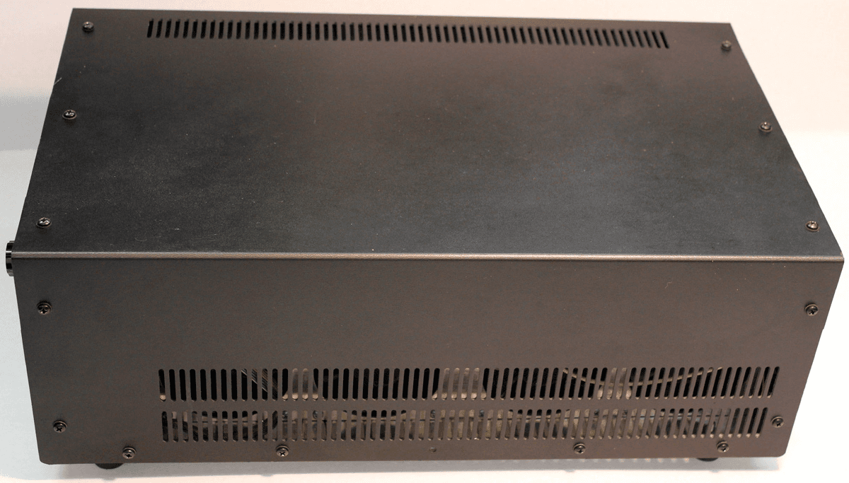
Click to zoom
Application Details
- Equipment Class
- AMP - Amplifier
- Date of Grant
- Sep 02, 2013
- Application Purpose
- Original Equipment
- Date of Application
- Apr 21, 2013
- Equipment Note
- ALS1306 amateur radio linear amplifier
- Frequency Range
- 1.80000000 - 54.00000000
- Company
- Ameritron
- Country
- United States
Documents & Files
Document Text
Text extracted from the exhibit documents filed with the FCC. Open a document above to read the original.
Users Manual
Ameritron ALS-1306 1200-Watt 160-6 Meter T-MOSFET AMPLIFIER The Ameritron ALS-1306 is 1200-watt PEP nominal output, 160- through 6-meter amateur radio band (1.8-54 MHz) solid-state amplifier. The compact 10” wide by 6-1/2” high amplifier package, with a depth of only 18”, fits nearly any station configuration. The attractive desktop amplifier unit weighs only 24 pounds. The ALS- 1306 meets or exceeds all FCC requirements governing amateur radio external power amplifiers. Fan speed is regulated by temperature sensors, assuring conservative cooling with minimal noise. Protection circuitry reduces power as transistors approach conservative thermal limits, and disables the amplifier before the transistors exceed safe operating temperature limits. The ALS-1306 uses eight 50-volt, conservatively rated, linear RF MOSFETS. These MOSFET’s are primarily designed for linear power amplifier applications, not class-C or pulse service. They provide exceptionally low SSB distortion when compared to most other solid-state devices. Nominal driving power is 100-watts for 1200- watts output (approximately 11 dB gain) on most bands. T/R (transmit-receive) switching is through a pair of sequenced miniature relays on a plug-in module. The plug in module facilitates relay servicing or maintenance. T/R switching time is approximately five milliseconds. The T/R “Relay” control jack is well within the range of almost any transceiver or radio. The “Relay” jack has an open circuit voltage of 13-volts, and closed circuit current less than 20 mA. Virtually any modern amateur radio will directly key this amplifier. This amplifier includes full metering using large easy-to-read conventional panel meters. An external 50-volt 50-ampere regulated power supply powers the ALS-1306. The supply is wired for 240 VAC (200-260 VAC, 50-60 Hz, 15 amperes), but can be rewired for 120 VAC operation for lighter duty operation. ALS-1306 Exihibit VIII Page 1 / 27 TABLE OF CONTENTS GENERAL OVERVIEW ........................................................................................................................ 1 TABLE OF CONTENTS ....................................................................................................................... 2 AMPLIFIER FEATURES ...................................................................................................................... 3 INSTALLATION.................................................................................................................................... 4 Airflow Clearances ............................................................................................................................ 4 Accessory Equipment and Devices ................................................................................................... 4 Installation, Wiring, and Connections ................................................................................................ 4 Station Ground .................................................................................................................................. 5 Grounding.......................................................................................................................................... 5 Coaxial Line Isolators ........................................................................................................................ 6 AMPLIFIER REAR PANEL .................................................................................................................. 6 POWER SUPPLY ................................................................................................................................. 7 Power Line Requirements ................................................................................................................. 7 Power Supply Features ..................................................................................................................... 8 Power Supply Location...................................................................................................................... 8 INTERCONNECTION WIRING............................................................................................................. 9 AMPLIFIER FRONT PANEL .............................................................................................................. 10 Meters (1 and 2) .............................................................................................................................. 10 INITIAL OPERATION ......................................................................................................................... 11 OPERATION....................................................................................................................................... 12 MARS OR CAP OPERATION ............................................................................................................ 12 ALS-1306 FUNCTIONAL OVERVIEW ............................................................................................... 13 General Operation ...........................................................................................................................13 Power Division................................................................................................................................. 13 PAM-606 (power amplifier modules) ............................................................................................... 13 2KWF6 Lowpass Filter Assembly ....................................................................................................14 Control Functions and Protection Logic........................................................................................... 14 Band Decoding................................................................................................................................ 15 Temperature..................................................................................…
Text truncated - open the document above for the full version.
Attestation Statements
MFJ Engineering 371 Dean Rd. Barnesville, GA 30204 Ph 770-358-3335 FAX 770-358-7880 April 15, 2013 Attestation Statement This certification is for production quantities of an amateur radio service linear amplifier. Maximum power permitted by FCC rules is 1500 watts PEP on all modes licensed for the Amateur Radio service under part 97. This amplifier has a 1200-watt PEP maximum rated output amplifier. Ameritron division of MFJ Enterprises will be the sole manufacturer of this product. Ameriton, of Starkville, MS, is a division of MFJ Enterprises, Inc. This amplifier meets or exceeds all requirements of CFR 47 part 97.317 as of April 15, 2013: § 97.317 Standards for certification of external RF power amplifiers. (a) To receive a grant of certification, the amplifier must: (1) Satisfy the spurious emission standards of § 97.307 (d) or (e) of this part, as applicable, when the amplifier is operated at the lesser of 1.5 kW PEP or its full output power and when the amplifier is placed in the “standby” or “off” positions while connected to the transmitter. (2) Not be capable of amplifying the input RF power (driving signal) by more than 15 dB gain. Gain is defined as the ratio of the input RF power to the output RF power of the amplifier where both power measurements are expressed in peak envelope power or mean power. (3) Exhibit no amplification (0 dB gain) between 26 MHz and 28 MHz. (b) Certification shall be denied when: (1) The Commission determines the amplifier can be used in services other than the Amateur Radio Service, or (2) The amplifier can be easily modified to operate on frequencies between 26 MHz and 28 MHz. [71 FR 66465, Nov. 15, 2006] ALS-1306 Exihibit I Page 1 / 3 Section 97.317 (a) (1) This amplifier exceeds spurious and harmonic emission suppression requirements outlined below in 97.307 (d) and (e), both at full rated output of 1200 watts PEP and at any power level below full rated output. In addition, when on standby, this amplifier is directly bypassed by a mechanical relay. Since non-linear devices of any kind are present, it does not alter any signal applied to radio frequency ports. Section 97.317 (a) (2) This amplifier has less than 15 dB gain on all frequencies. Section 97.317 (a) (3) This amplifier is inoperable between 25 MHz and 28 MHz. Application of any signal greater than 50 milliwatts between 25 and 28 MHz automatically forces this amplifier into lockout, where gain reverts to 0 dB. Section 97.317 (b) (1) and (2) Because the lockout feature is embedded in the control PIC, the out-of-band lockout feature cannot be removed. There are no jumpers, diodes, or programming steps to defeat the lockout. If the control board is removed or disabled, the amplifier will stop functioning. This amplifier meets all sections of 97.307 Emission Standards applicable to external RF power amplifiers, as of April 15, 2013: § 97.307 Emission standards. (d) For transmitters installed after January 1, 2003, the mean power of any spurious emission from a station transmitter or external RF power amplifier transmitting on a frequency below 30 MHz must be at least 43 dB below the mean power of the fundamental emission. For transmitters installed on or before January 1, 2003, the mean power of any spurious emission from a station transmitter or external RF power amplifier transmitting on a frequency below 30 MHz must not exceed 50 mW and must be at least 40 dB below the mean power of the fundamental emission. For a transmitter of mean power less than 5 W installed on or before January 1, 2003, the attenuation must be at least 30 dB. A transmitter built before April 15, 1977, or first marketed before January 1, 1978, is exempt from this requirement. (e) The mean power of any spurious emission from a station transmitter or external RF power amplifier transmitting on a frequency between 30-225 MHz must be at least 60 dB below the mean power of the fundamental. For a transmitter having a mean power of 25 W or less, the mean power of any spurious emission supplied to the antenna transmission line must not exceed 25 μW and must be at least 40 dB below the mean power of the fundamental emission, but need not be reduced below the power of 10 μW. A transmitter built before April 15, 1977, or first marketed before January 1, 1978, is exempt from this requirement. ALS-1306 Exihibit I Page 2 / 3 97.307d specifies harmonic and spurious levels at least 43 dB below fundamental, and not to exceed 50 mW, for operation below 30 MHz. With 1200 watts, the harmonic and spurious limit is -43.8 dB. 97.307e specifies harmonic and spurious levels at least 60 dB below fundamental for operation between 30 MHz and 225 MHz. This amplifier exceeds 97.307 requirements. Charles T. Rauch Engineer MFJ Enterprises ALS-1306 Exihibit I Page 3 / 3
Attestation Statements
ALS-1306 Exihibit I Page 1 / 3 April 15, 2013 Attestation Statement This certification is for production quantities of an amateur radio service linear amplifier. Maximum power permitted by FCC rules is 1500 watts PEP on all modes licensed for the Amateur Radio service under part 97. This amplifier has a 1200-watt PEP maximum rated output amplifier. Ameritron division of MFJ Enterprises will be the sole manufacturer of this product. Ameriton, of Starkville, MS, is a division of MFJ Enterprises, Inc. This amplifier meets or exceeds all requirements of CFR 47 part 97.317 as of April 15, 2013: § 97.317 Standards for certification of external RF power amplifiers. (a) To receive a grant of certification, the amplifier must: (1) Satisfy the spurious emission standards of § 97.307 (d) or (e) of this part, as applicable, when the amplifier is operated at the lesser of 1.5 kW PEP or its full output power and when the amplifier is placed in the “standby” or “off” positions while connected to the transmitter. (2) Not be capable of amplifying the input RF power (driving signal) by more than 15 dB gain. Gain is defined as the ratio of the input RF power to the output RF power of the amplifier where both power measurements are expressed in peak envelope power or mean power. (3) Exhibit no amplification (0 dB gain) between 26 MHz and 28 MHz. (b) Certification shall be denied when: (1) The Commission determines the amplifier can be used in services other than the Amateur Radio Service, or (2) The amplifier can be easily modified to operate on frequencies between 26 MHz and 28 MHz. [71 FR 66465, Nov. 15, 2006] Ameritron / MFJ Engineering 371 Dean Rd. Barnesville, GA 30204 Ph 770-358-3335 FAX 770-358-7880 ALS-1306 Exihibit I Page 2 / 3 Section 97.317 (a) (1) This amplifier exceeds spurious and harmonic emission suppression requirements outlined below in 97.307 (d) and (e), both at full rated output of 1200 watts PEP and at any power level below full rated output. In addition, when on standby, this amplifier is directly bypassed by a mechanical relay. Since non-linear devices of any kind are present, it does not alter any signal applied to radio frequency ports. Section 97.317 (a) (2) This amplifier has less than 15 dB gain on all frequencies. Section 97.317 (a) (3) This amplifier is inoperable between 25 MHz and 28 MHz. Application of any signal greater than 50 milliwatts between 25 and 28 MHz automatically forces this amplifier into lockout, where gain reverts to 0 dB. Section 97.317 (b) (1) and (2) Because the lockout feature is embedded in the control PIC, the out-of-band lockout feature cannot be removed. There are no jumpers, diodes, or programming steps to defeat the lockout. If the control board is removed or disabled, the amplifier will stop functioning. This amplifier meets all sections of 97.307 Emission Standards applicable to external RF power amplifiers, as of April 15, 2013: § 97.307 Emission standards. (d) For transmitters installed after January 1, 2003, the mean power of any spurious emission from a station transmitter or external RF power amplifier transmitting on a frequency below 30 MHz must be at least 43 dB below the mean power of the fundamental emission. For transmitters installed on or before January 1, 2003, the mean power of any spurious emission from a station transmitter orexternal RF power amplifier transmitting on a frequency below 30 MHzmust not exceed 50 mW and must be at least 40 dB below the mean power of the fundamental emission. For a transmitter of mean power less than 5 W installed on or before January 1, 2003, the attenuation must be at least 30 dB. A transmitter built before April 15, 1977, or first marketed before January 1, 1978, is exempt from this requirement. (e) The mean power of any spurious emission from a station transmitter or external RF power amplifier transmitting on a frequency between 30-225 MHzmust be at least 60 dB below the mean power of the fundamental. For a transmitter having a mean power of 25 W or less, the mean power of any spurious emission supplied to the antenna transmission line must not exceed 25 μW and must be at least 40 dB below the mean power of the fundamental emission, but need not be reduced below the power of 10 μW. A transmitter built before April 15, 1977, or first marketed before January 1, 1978, is exempt from this requirement. ALS-1306 Exihibit I Page 3 / 3 97.307d specifies harmonic and spurious levels at least 43 dB below fundamental, and not to exceed 50 mW, for operation below 30 MHz. With 1200 watts, the harmonic and spurious limit is -43.8 dB. 97.307e specifies harmonic and spurious levels at least 60 dB below fundamental for operation between 30 MHz and 225 MHz. This amplifier exceeds 97.307 requirements. Charles T. Rauch Engineer Ameritron / MFJ Enterprises
External Photos
Exhibit II External photos of HO82WUALS1306 ALS-1306 amplifier. Front and Meters Left Side ALS-1306 Exihibit II Page 1 / 2 Right Side Rear ALS-1306 Exihibit II Page 2 / 2
ID Label/Location Info
FCC rules 2.925 and 2.926 require we show the FCC ID label of this part 97 device and the location where the label appears on the device. The FCC ID label will appear on the rear panel below the power connector: Exhibit III FCC ID label ALS-1306 Exihibit III Page 1 / 1 This is the FCC ID label. The number following “ALS1306-“ is a sequential serial number:
Internal Photos
Top view ALS-1306.................................................................................................1 Front Panel..............................................................................................................2 Rear Panel..............................................................................................................2 Left Side..................................................................................................................3 Right Side................................................................................................................3 2KWF6....................................................................................................................4 BSW2......................................................................................................................5 CB2.........................................................................................................................5 MB1.........................................................................................................................6 PAM-606.................................................................................................................7 PD8.........................................................................................................................8 RJ45........................................................................................................................9 RLY.........................................................................................................................9 SWR........................................................................................................................10 Top view ALS-1306 ALS-1306 Exihibit IV Page 1 / 10 Exhibit IV Internal photos of HO82WUALS1306 ALS-1306 amplifier. Front panel Rear panel ALS-1306 Exihibit IV Page 2 / 10 Left side Right side view ALS-1306 Exihibit IV Page 3 / 10 2KWF6 bottom 2KWF6 ALS-1306 Exihibit IV Page 4 / 10 BSW2 (top/bottom) CB2 (top/bottom) ALS-1306 Exihibit IV Page 5 / 10 ALS-1306 Exihibit IV Page 6 / 10 MB1 (top/bottom) ALS-1306 Exihibit IV Page 7 / 10 PAM-606 (PA module) bottom PAM-606 A and B (PA modules) PD8 ALS-1306 Exihibit IV Page 8 / 10 RJ45 (top/bottom) RLY ALS-1306 Exihibit IV Page 9 / 10 ALS-1306 Exihibit IV Page 10 / 10
Operational Description
Exhibit V Operational description HO82WUALS1306 ALS-1306 Technical and Operational Overview The ALS-1306 is an amateur radio multiband radio frequency linear power amplifier. This device requires certification. This device complies with technical standards of CFR Title 47 part 97.317(a) and (b) as of April 2013. General Operation This linear amplifier covers the 160, 80, 40, 30, 20, 17, 15, 12, 10, and 6-meter amateur bands. Up to 100-watts exciter power is applied to relay RLY1 on circuit board RLY. With the main power OFF, the STANDBY/OPERATE switch on STANDBY, with a fault warning LED illuminated, or with the rear panel RELAY jack ungrounded, RLY1 bypasses through RLY2 directly to the antenna port. When power is ON, the STANDBY/OPERATE switch in the operate position, and the rear panel RELAY control line held low (below 1 volt), exciter power is routed through RLY1 to the PD8 power divider board. Power Division The PD8 power divider board attenuates the exciter input signal, and divides exciter power equally, between two 600-watt power amplifier modules. It is 50-ohms on all three ports, with 8.2 dB nominal attenuation to each output port. The PD8 circuit board consists of a conventional magic-T power divider, components T2 and R7. This T divides drive power into two equal-power signals. Each signal path has a 5 dB attenuator consisting of high power resistors R1 through R6. The 5 dB attenuators on each output port terminate the T in 50-ohms and provide an additional 10 dB of input port isolation between the two PAM’s. With a 50-ohm source, in excess of 30 dB port-to-port isolation occurs between PAM inputs. A minimum of 16 dB isolation occurs regardless of input port termination. The attenuators also work in concert with the magic-T to provide a 50-ohm input termination for each PAM. The 50-ohm termination and input port isolation results in unconditionally stable PAM’s. PAM-606 (power amplifier modules) Power amplification comes from two 600-watt power amplifier modules. Each PA module (PAM-606) uses four MFR-150 field effect transistors. Each MRF-150 has 100 mA to 300 mA quiescent current. Transistor conduction angle is slightly over 180-degrees, providing linear class-AB operation. While the precise value of quiescent current has little effect on linearity, it is very important to adjust all eight FET’s to the same quiescent current. Target current is typically 150 mA in this design. Normal dc drain operating voltage is approximately 50-volts. Be aware bias control rotation is reversed in CB2 boards, as compared to the previous generation ALS- 1300’s CB1. When servicing any solid state PA, always verify function of bias and set for minimum bias before applying drain voltage. ALS-1306 Exihibit V Page 1 / 4 Unlike standard Motorola based modules, the PAM-606 modules use two diametrically opposed push-pull pairs of 150-watt MOSFET’s. The 300-watt push-pull pairs drive balanced VHF striplines. The balanced striplines combine at a matching transformer. The linear RF power FET’s mount on a forced-air-cooled aluminum heatsink. Two dc fans cool each PAM-606 module. Two thermistors (PAM-606 R2) sense power amplifier transistor temperature. Transistor temperature thermistor R2 regulates bias voltage, reducing bias voltage as transistor temperature increases. This bias feedback system keeps transistor quiescent current stable independent of transistor junction temperatures. PAM-606 thermistors R2 also feed a comparator that removes drive when transistor temperatures approach unsafe levels. Bias voltages for the PAM-606 modules come from the CB-2 control board assembly. Each transistor has an individual bias adjustment, with minimum bias counter-clockwise from the top view. This is opposite the control function in older CB1 assemblies. A second set of thermistors (PAM-606 R1) monitor heatsink temperatures. Voltages from thermistors R1 regulate fan speed, increasing fan speed and airflow as the heat sink warms. The PAM-606 modules employ significant negative feedback to reduce gain, improve gain flatness, improve linearity, and ensure stability. The FET’s have direct resistive voltage feedback across each individual transistor from drain-to-gate, as well as push-pull transformer (T2) coupled feedback common to the push-pull circuit. Push-pull operation, negative feedback, and linear biasing of FET’s provide significant pre-filter harmonic suppression. The characteristics of linear high-voltage FET’s are very much like those of triode vacuum tubes. While this amplifier will run more than 1200-watts PEP output, linearity might suffer. Ameritron recommends running 1200-watts PEP or less for maximum linearity, although most amplifiers will remain clean above 1200-watts PEP. Following these instructions, this amplifier will have IM performance comparable to the best vacuum tube linear amplifiers. 2KWF6 Lowpass Filter Assembly Each PAM-606 module connects directly to the 2KWF6 circuit board assembly through 50-ohm cables. Both PAM’s feed into a 50-ohm high power combiner. The combiner is integrated into the 2KWF6. This combiner isolates the two PAM-606 inputs while maintaining 50-ohm impedance. Two 25-watt 200-ohm power resistors, R7 and R8, dissipate power level or phase errors between the PAM inputs. Voltage step-down transformer T1 senses voltage across combiner dump resistors, R7 and R8. T1 is located on the 2KWF6 lowpass filter board. This voltage, representing PA combiner unbalance, appears on the front panel multimeter as a “PAB” (power amplifier balance) indication. PA unbalance reference voltage also feeds a comparator on the CB2 control board. This comparator disables the PA in the event the power amplifiers become significantly unbalanced, and illuminates the PA front panel light. The output of the high-power combiner enters the filter section through a directional coupler consisting of current transformer T2, capacitors C36-38, C40-42, and resistors R4, 5 and 6. This directional coupler …
Text truncated - open the document above for the full version.
Operational Description
ALS-1306 Exihibit V Page 1 / 5 Exhibit V Operational description HO82WUALS1306 ALS-1306 Technical and Operational Overview The ALS-1306 is an amateur radio multiband radio frequency linear power amplifier. This device requires certification. This device complies with technical standards of CFR Title 47 part 97.317(a) and (b) as of April 2013. General Operation This linear amplifier covers the 160, 80, 40, 30, 20, 17, 15, 12, 10, and 6-meter amateur bands. Up to 100-watts exciter power is applied to relay RLY1 on circuit board RLY. With the main power OFF, the STANDBY/OPERATE switch on STANDBY, with a fault warning LED illuminated, or with the rear panel RELAY jack ungrounded, RLY1 bypasses through RLY2 directly to the antenna port. When power is ON, the STANDBY/OPERATE switch in the operate position, and the rear panel RELAY control line held low (below 1 volt), exciter power is routed through RLY1 to the PD8 power divider board. Power Division The PD8 power divider board attenuates the exciter input signal, and divides exciter power equally, between two 600-watt power amplifier modules. It is 50-ohms on all three ports, with 8.2 dB nominal attenuation to each output port. The PD8 circuit board consists of a conventional magic-T power divider, components T2 and R7. This T divides drive power into two equal-power signals. Each signal path has a 5 dB attenuator consisting of high power resistors R1 through R6. The 5 dB attenuators on each output port terminate the T in 50-ohms and provide an additional 10 dB of input port isolation between the two PAM’s. With a 50-ohm source, in excess of 30 dB port-to-port isolation occurs between PAM inputs. A minimum of 16 dB isolation occurs regardless of input port termination. The attenuators also work in concert with the magic-T to provide a 50-ohm input termination for each PAM. The 50-ohm termination and input port isolation results in unconditionally stable PAM’s. Ameritron / MFJ Engineering 371 Dean Rd. Barnesville, GA 30204 Ph 770-358-3335 FAX 770-358-7880 ALS-1306 Exihibit V Page 2 / 5 PAM-606 (power amplifier modules) Power amplification comes from two 600-watt power amplifier modules. Each PA module (PAM-606) uses four MFR-150 field effect transistors. Each MRF-150 has 100 mA to 300 mA quiescent current. Transistor conduction angle is slightly over 180-degrees, providing linear class-AB operation. While the precise value of quiescent current has little effect on linearity, it is very important to adjust all eight FET’s to the same quiescent current. Target current is typically 150 mA in this design. Normal dc drain operating voltage is approximately 50-volts. Be aware bias control rotation is reversed in CB2 boards, as compared to the previous generation ALS- 1300’s CB1. When servicing any solid state PA, always verify function of bias and set for minimum bias before applying drain voltage. Unlike standard Motorola based modules, the PAM-606 modules use two diametrically opposed push-pull pairs of 150-watt MOSFET’s. The 300-watt push-pull pairs drive balanced VHF striplines. The balanced striplines combine at a matching transformer. The linear RF power FET’s mount on a forced-air-cooled aluminum heatsink. Two dc fans cool each PAM-606 module. Two thermistors (PAM-606 R2) sense power amplifier transistor temperature. Transistor temperature thermistor R2 regulates bias voltage, reducing bias voltage as transistor temperature increases. This bias feedback system keeps transistor quiescent current stable independent of transistor junction temperatures. PAM-606 thermistors R2 also feed a comparator that removes drive when transistor temperatures approach unsafe levels. Bias voltages for the PAM-606 modules come from the CB-2 control board assembly. Each transistor has an individual bias adjustment, with minimum bias counter-clockwise from the top view. This is opposite the control function in older CB1 assemblies. A second set of thermistors (PAM-606 R1) monitor heatsink temperatures. Voltages from thermistors R1 regulate fan speed, increasing fan speed and airflow as the heat sink warms. The PAM-606 modules employ significant negative feedback to reduce gain, improve gain flatness, improve linearity, and ensure stability. The FET’s have direct resistive voltage feedback across each individual transistor from drain-to-gate, as well as push-pull transformer (T2) coupled feedback common to the push-pull circuit. Push-pull operation, negative feedback, and linear biasing of FET’s provide significant pre-filter harmonic suppression. The characteristics of linear high-voltage FET’s are very much like those of triode vacuum tubes. While this amplifier will run more than 1200-watts PEP output, linearity might suffer. Ameritron recommends running 1200-watts PEP or less for maximum linearity, although most amplifiers will remain clean above 1200-watts PEP. Following these instructions, this amplifier will have IM performance comparable to the best vacuum tube linear amplifiers. ALS-1306 Exihibit V Page 3 / 5 2KWF6 Lowpass Filter Assembly Each PAM-606 module connects directly to the 2KWF6 circuit board assembly through 50-ohm cables. Both PAM’s feed into a 50-ohm high power combiner. The combiner is integrated into the 2KWF6. This combiner isolates the two PAM-606 inputs while maintaining 50-ohm impedance. Two 25-watt 200-ohm power resistors, R7 and R8, dissipate power level or phase errors between the PAM inputs. Voltage step-down transformer T1 senses voltage across combine…
Text truncated - open the document above for the full version.
Contact Information
Applicant
Martin Jue(President)
Technical Contact
MFJ Enterprises EngineeringCharles Thomas Rauch
[email protected]770-358-3335
371 Dean Rd. · Barnesville, Georgia · United States
Non-Technical Contact
MFJ Enterprises EngineeringCharles Thomas Rauch
[email protected]770-358-3335
Technical Specifications
| # | Rule Parts | Frequency Range | Power Output | Emission |
|---|---|---|---|---|
| 3 | 97 | 1.8 MHz - 54 MHz | 1200 W | J3E |
Other Applications from Ameritron

HO82WUALS1406
Apr 15, 2021Linear Amplifier
Equipment Class
AMP - AmplifierHO82WUAL572
Mar 23, 1997Emissions per Section 97.305
Equipment Class
TNB - Licensed Non-Broadcast Station TransmitterHO82WUAL800
Aug 02, 1995Emissions per Section 97.305
Equipment Class
TNB - Licensed Non-Broadcast Station TransmitterHO82WUAL800H
Mar 15, 1995Emissions Per Section 97.305
Equipment Class
TNB - Licensed Non-Broadcast Station TransmitterHO82WUALS500M
Feb 07, 1993Emissions per Section 97.305
Equipment Class
TNB - Licensed Non-Broadcast Station Transmitter