HOJTXT900900 MHz R/C Transmitter
Teletrix Corporation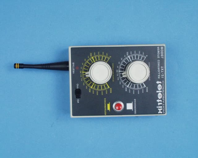
Click to zoom
Application Details
- Equipment Class
- DXX - Part 15 Low Power Communication Device Transmitter
- Date of Grant
- Oct 01, 2002
- Application Purpose
- Original Equipment
- Date of Application
- Oct 01, 2002
- Equipment Note
- 900 MHz R/C Transmitter
- Frequency Range
- 920.80000000 - 921.80000000
- Company
- Teletrix Corporation
- Country
- United States
Documents & Files
Document Text
Text extracted from the exhibit documents filed with the FCC. Open a document above to read the original.
Users Manual
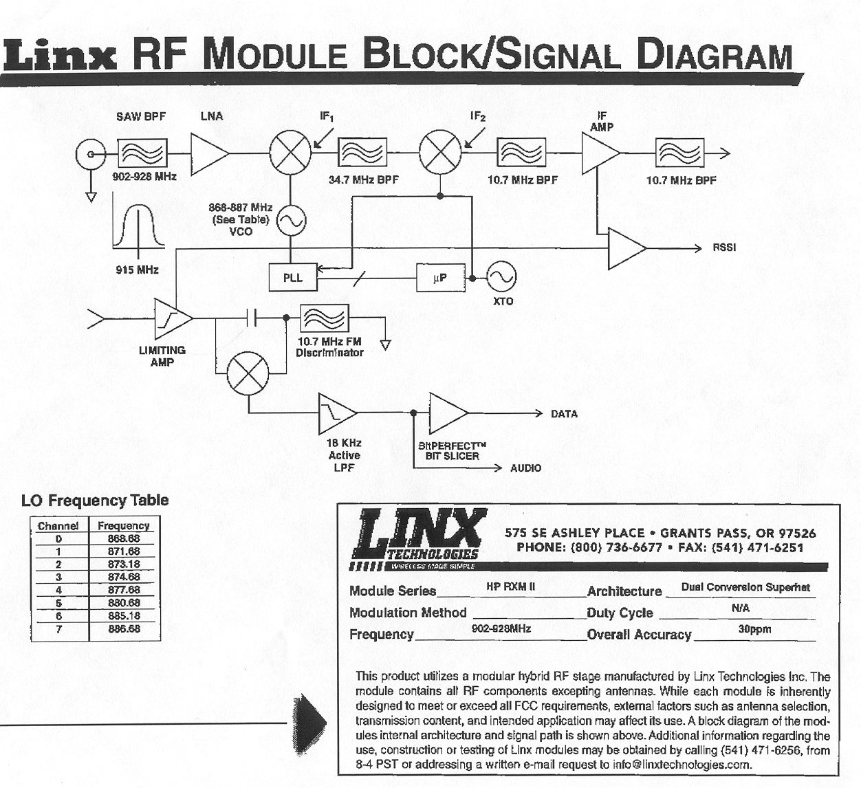
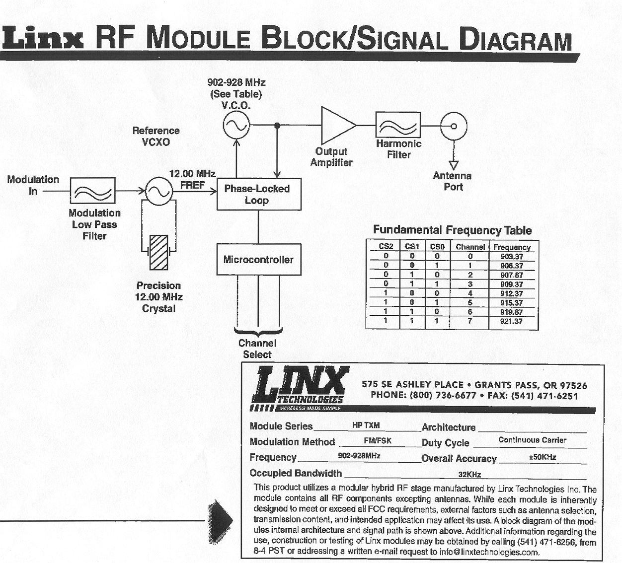
Radiation Survey Instrument Simulators Model TXR-21 Owner’s Manual MODEL TXR-21 SURVEY METER SIMULATOR TELETRIX CORPORATION TXR-21 SURVEY METER SIMULATOR TABLE OF CONTENTS Page Safety Precautions 2 Electric Shock Hazards 2 Regarding RF Emissions 2 Introduction 3 About the Survey Meter Simulator 3 Controls and Indicators 3 Locations 3 Functions 4 Operation of the Instrument Package 5 Care and Maintenance 7 Handling 7 Batteries 7 2 MODEL TXR-21 SURVEY METER SIMULATOR SAFETY PRECAUTIONS Electric Shock Hazards The Model TXR-21 Survey Meter Simulator is powered by its self-contained battery pack that is charged by one of the supplied chargers. To reduce the risk of electric shock, make certain that the charger is removed before removing the cover of the TXR-21 Survey Meter Simulator. To prevent fire or shock hazard, do not expose any component part of the Survey Meter Simulator package to rain or moisture. There are no user serviceable parts within the TXT-21 Remote Controller except for the battery. If the battery is suspect, refer to qualified personnel only. When repair or adjustment is required in either the TXR-21 or TXT-21, refer to qualified personnel, as the risk of electric shock exists in these units. ****** CAUTION ****** Battery Charger is intended for 120 VAC indoor use only. Do not attempt to charge the TXR-21 Survey Meter Simulator or the TXT-21 Remote Controller with any charger other than the supplied charger with UL listing and CSA certification to avoid potential hazard from electric shock or fire. Regarding RF Emissions The 900 Series Remote Controller, TXT-21, uses RF (Radio Frequency) transmission for communications with the TXR-21. The operating frequencies are on 8 user-selectable channels between 902 and 928 MHz. ****** CAUTION ****** Changes or modifications not expressly approved by the party responsible for compliance could void the user's authority to operate the equipment. It is recommended that nuclear plant instrument personnel be notified of the operation of such a device if it is to be operated within or close to plant boundaries. A copy of the technical report filed with the FCC will be supplied upon request if compliance data is needed. Contact us at: Teletrix Corporation PO Box 14209 Pittsburgh, PA 15239 (412) 798-3636 3 MODEL TXR-21 SURVEY METER SIMULATOR INTRODUCTION Congratulations on your purchase of the Teletrix Survey Meter Simulator. The simulator has been designed with reliability of operation and simplicity of purpose and should yield years of trouble free operation with the proper maintenance and care. This manual is intended to provide the end-users with instructions on the functions, operations and care of the simulator. ABOUT THE SURVEY METER SIMULATOR The Teletrix Survey Meter Simulator is an operating replica of an actual GM survey meter radiation detector. The Teletrix Survey Meter Simulator produces an artificial reading of radiation levels by way of remote control versus directly reading a “live” source. The TXR-21 Simulator does not detect radiation. Instead, the TXT-21 Remote Controller excites the TXR-21 with a modulated RF data stream to produce an artificial reading of radiation levels. The operator of the TXT-21 Remote Controller merely sets a particular level of simulated radiation that the operator of the TXR-21 Survey Meter Simulator should be reading as a result of the actions being taken. The operator of the TXR-21 will be able to manipulate the controls on the TXR-21 to achieve the proper reading as transmitted by the TXT-21 Remote Controller. The complete instrument package you have received is ready for operation and comes with the following: 1 -- TXR-21 Survey Meter Simulator 1 -- TXT-21 Remote Controller 2 – Battery Chargers CONTROLS AND INDICATORS The controls and indicators on the TXR-21 provide the functions of an actual survey meter. The TXT-21 has only 3 controls that vary the indications obtained from the TXR-21. Locations TXR-21 Survey Meter Simulator • Meter -- Located on the front of the TXR-21 the meter is scaled from 0-500 COUNTS/MIN with a BATT TEST span and a high voltage scale from 0 to 2.5 KV. • Range Switch -- Located on the top of the TXR-21 this is a 6-position switch with 4 decades of range selection, BAT check, and ON/OFF function. • 6 external adjustment pots, one per range of indication, HV, and DIS located on the front of the case. • AUD -- 2-position toggle switch located on the front of the TXR-21 used to enable or disable the audio output. • F-S -- This switch is located on the front of the TXR-21 and used for controlling meter response. • RES -- A pushbutton located on the front of the TXR-21 used to reset the meter. • HV -- A pushbutton located on the front of the TXR-21 used to check the high voltage setting. 4 MODEL TXR-21 SURVEY METER SIMULATOR • BNC Connector -- Is provided to allow for attachment of a probe or probe simulator. • Charger Receptacle -- Mounted on the bottom edge of the case top. TXT-21 Remote Controller The controls and indicators on the TXT-21 and their locations are as follows: • ON/OFF -- This is a slide switch located on the front of theTXT-21. • COUNTS PER MINUTE -- The main output control knobs are located on the front of the TXT-21 with the BACKGROUND control in white and the CONTAMINATION control in yellow. • BACKGROUND/CONTAMINATION -- This pushbutton is on the front of the unit and indicates which of the above mentioned output control settings are being transmitted to the TXR-21. • BATTERY -- This red indicator is only visable when the unit is on or charging. • Charger Receptacle -- Mounted on the bottom edge of the case. Functions • Range Switch -- The functions of this 6-postion switch are as follows: • OFF -- Interrupts power to the TXR-21. • BAT -- Displays battery condition on the meter. An indication within the BATT TEST range indicates that the unit can be operated properly • 1K -- This is the 1000 times multiplier for meter reading • X100 -- This is the 100 …
Text truncated - open the document above for the full version.
External Photos
Front View Right Side View Rear View Left Side View Top View
ID Label/Location Info
Remote Controller Rear View Label Location This device complies with Part 15 of the FCC Rules. Operation is subject to the following two conditions: (1) this device may not cause harmful interference, and (2) this device must accept any interference received, including interference that may cause undesired operation. FCC ID: HOJTXT900 Pittsburgh, PA Made in the USA FCC Label
Internal Photos
Interior, Component Side Interior Circuit, Track Side Sub Assy. Top Sub Assy. Bottom Case Interior Battery Pack
Operational Description
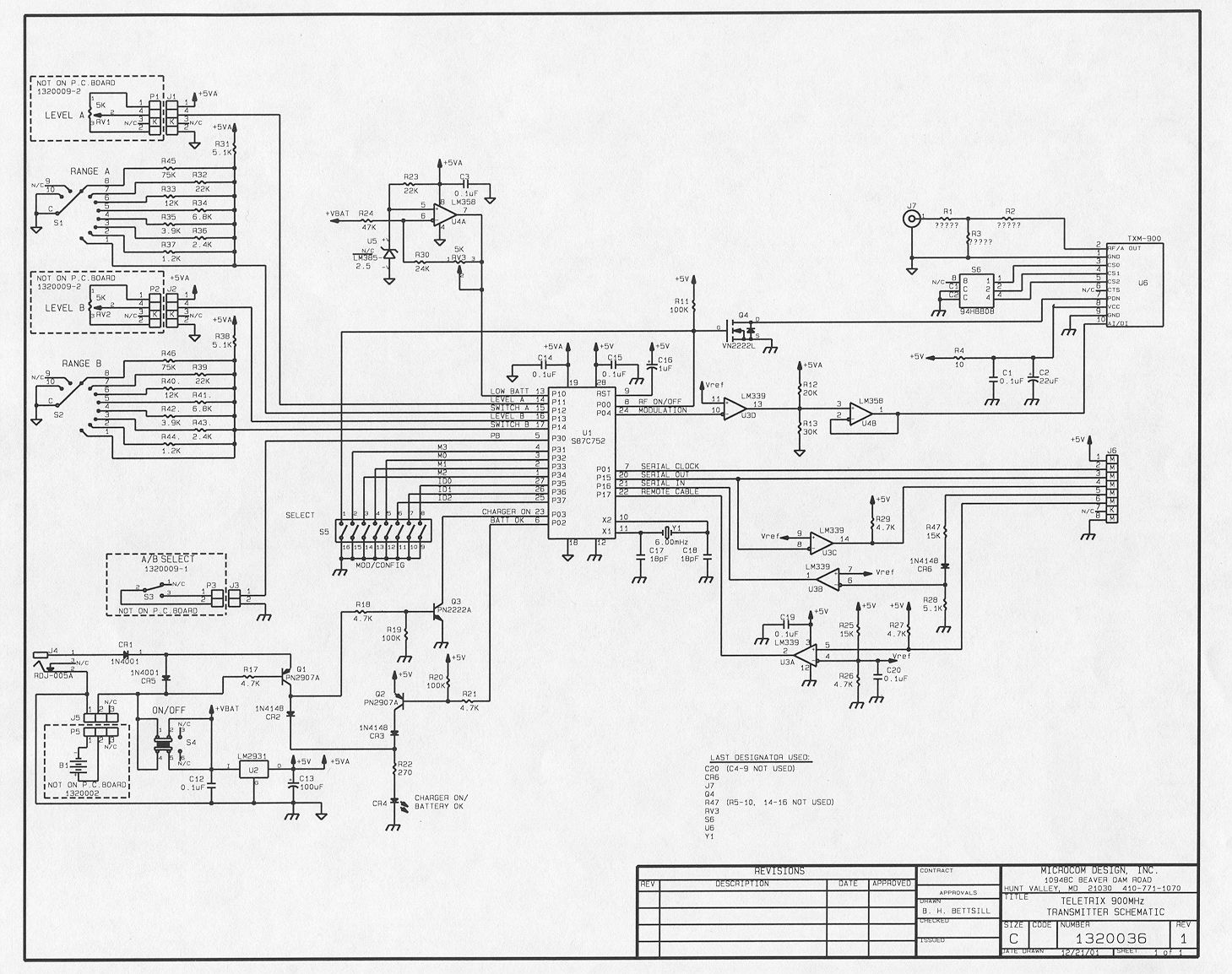
Operational Description The Teletrix Survey Meter Simulator is an operating replica of an actual GM survey meter radiation detector. The Teletrix Survey Meter Simulator produces an artificial reading of radiation levels by way of remote control versus directly reading a “live” source. The TXR-21 simulator does not detect radiation. Instead, the TXT-21 Remote Controller excites the TXR-21 with a modulated RF data stream to produce an artifical reading of radiation levels. The operator of the TXT-21 Remote Controller merely sets a particular level of simulated radiation that the operator of the TXR-21 should be reading as a result of the actions being taken. The operator of the TXR-21 will be able to manipulate the controls on the TXR-21 to achieve the proper reading as transmitted by the TXT-21 Remote Controller.
Test Report
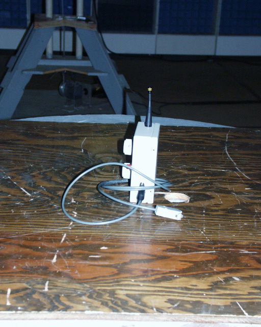
INTRODUCTION Procedures of ANSI 63.4 (1992) were used. COMPLIANCE_WITH_SECTION_15.249_OF_PART_15 15.249(a,b) The field strength of the radiation emission was measured and found to comply with the limits established by 15.249(a) and 15.209. (See data of Table 1.) 15.249(c) Emissions radiated outside of the specified frequency bands, except for harmonics, were attenuated by at least 50 dB below the level of the fundamental or to the general radiated emission limits in 15.209, (whichever is the lesser attenuation). See Figure 1. Operating channels are limited to the 920.8 – 921.8 MHz band in order to provide 1 MHz band- edge compliance with any close-in spectra less than 50 dB below carrier. 15.207(a) No AC power line conducted measurements are required; the device operates only from batteries. DATA Tables and Figures referenced above follow immediately after this page. Description of measurement procedures and test equipment used in the measurements follow the data pages. TABLE 1 RADIATED SPURIOUS EMISSIONS Measured at 3 meters PART 15(B) PARA. 15.249 Frequency of Meter Antenna Field 1 Emission Reading Factor Intensity FCC Limit dB to (MHz) (dBm) (dB) uV/m @ 3m uV/m @ 3m Limit 921.330 -44.2 31.1 49716.4 50000 0.05V 1842.645 -91.6 27.5 139.6 500 11V 2764.110 -100.0 30.2 72.4 500 17V 3685.480 -103.6 32.8 64.6 500 18V 4606.850 -102.4 33.2 77.6 500 16V 5528.220 -104.4 35.0 75.9 500 16V 6449.590 -102.0 35.8 109.6 500 13V 7370.960 -100.0 37.3 164.1 500 10H 8292.330 -105.5 38.1 95.5 500 14V 9213.700 -101.5 38.5 158.5 500 10V Note 1: uV/m = Log -dB/m 20 dBu = dBm + antenna factor + 107 *Measured at 1 meter, extrapolated to 3 meters. RBW 100 kHz to 1 GHz; 1 MHz > 1 GHz. Reduced if CW signal. H,V: Worst-case test antenna polarization. RADIATED SPURIOUS EMISSIONS FCC ID: HOJTXT900 TABLE 1 2 FIGURE 1 OCCUPIED BANDWIDTH FCC ID: HOJTXT900 FIGURE 1 3 PROCEDURES,_RADIATED_SPURIOUS_EMISSIONS The field strength of the radiated emissions from the test sample was measured following ANSI 63.4 (1992) at a distance of 3 meters to the third harmonic at which time the horn antennas were moved to 1 meter. The spectrum was scanned from 30 MHz to the tenth harmonic using a Tektronix 494P spectrum analyzer. Measurement procedure included recording the worst-case field strength for receiving test antenna polarization, test antenna height variation from 1 meter to 4 meters and test sample rotation, and test sample antenna in both vertical and horizontal plane. The test sample was placed on a rotatable 80 cm high wooden stand. The receiving antenna, placed 3 meters from the test sample, was a Compliance Design dipole, or Polarad CA-L, CA-S, or EMCO 3115 Horns. RBW used on the TEK 494P was 100 kHz to 1 GHz; 1 MHz > 1 GHz. Measurements above the 2nd harmonic were made at 1 meter extrapolated to 3 m; peak responding detector, VBW = > than RBW. The device was operated from a battery supply enclosed in the EUT. The spectrum was checked from 30 MHz to the tenth harmonic. All emissions not reported were less than 50 uV/m @ 3m or in system noise. Tabulation of the measurements are shown in Table 1. 4
Test Report
The antenna is a Linx part # ANT-916-PW-QW (Linx says it is Part 15 compliant) and is permanently mounted to the case thru a 1/4" hole in the case. The antenna is fed thru the hole using RG-174 Coax cable and is terminated in an right-angle crimp SMA connector which is a Johnson Part # 142-0403-101 which is screwed on to a mating connector on the circuit board.
Contact Information
Applicant
Michael E Podobnik(President)
Test Firm
Carl T. Jones CorporationCarl Jones
Technical Specifications
| # | Rule Parts | Frequency Range | Power Output |
|---|---|---|---|
| 1 | 15C | 920.8 MHz - 921.8 MHz | - |
Other Applications from Teletrix Corporation
HOJTXT-1A
Jan 17, 1991Remote Control Transmitter
Equipment Class
DXX - Part 15 Low Power Communication Device TransmitterHOJ2XGTR20
Feb 02, 1989DXX - Part 15 Low Power Communication Device Transmitter
Equipment Class
DXX - Part 15 Low Power Communication Device Transmitter