HQKKMEMFYY33RF Mouse
Key Mouse Electronic Enterprise Co Ltd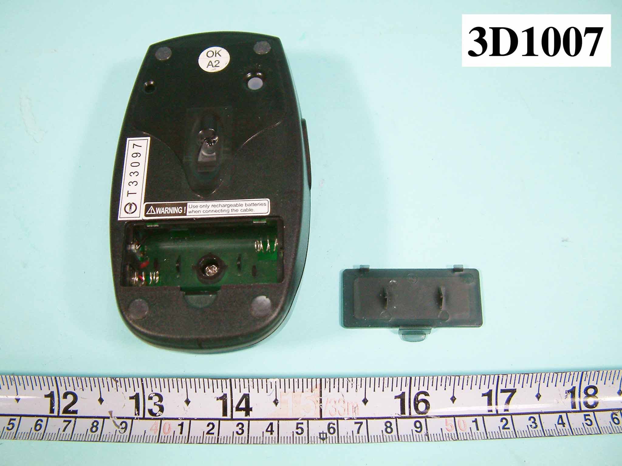
Click to zoom
Application Details
- Equipment Class
- DXX - Part 15 Low Power Communication Device Transmitter
- Date of Grant
- Apr 25, 2004
- Application Purpose
- Original Equipment
- Date of Application
- Apr 25, 2004
- Equipment Note
- RF Mouse
- Frequency Range
- 26.96000000 - 27.28000000
- Country
- Taiwan
Documents & Files
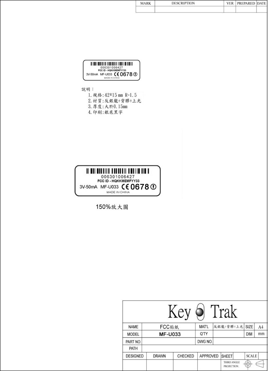
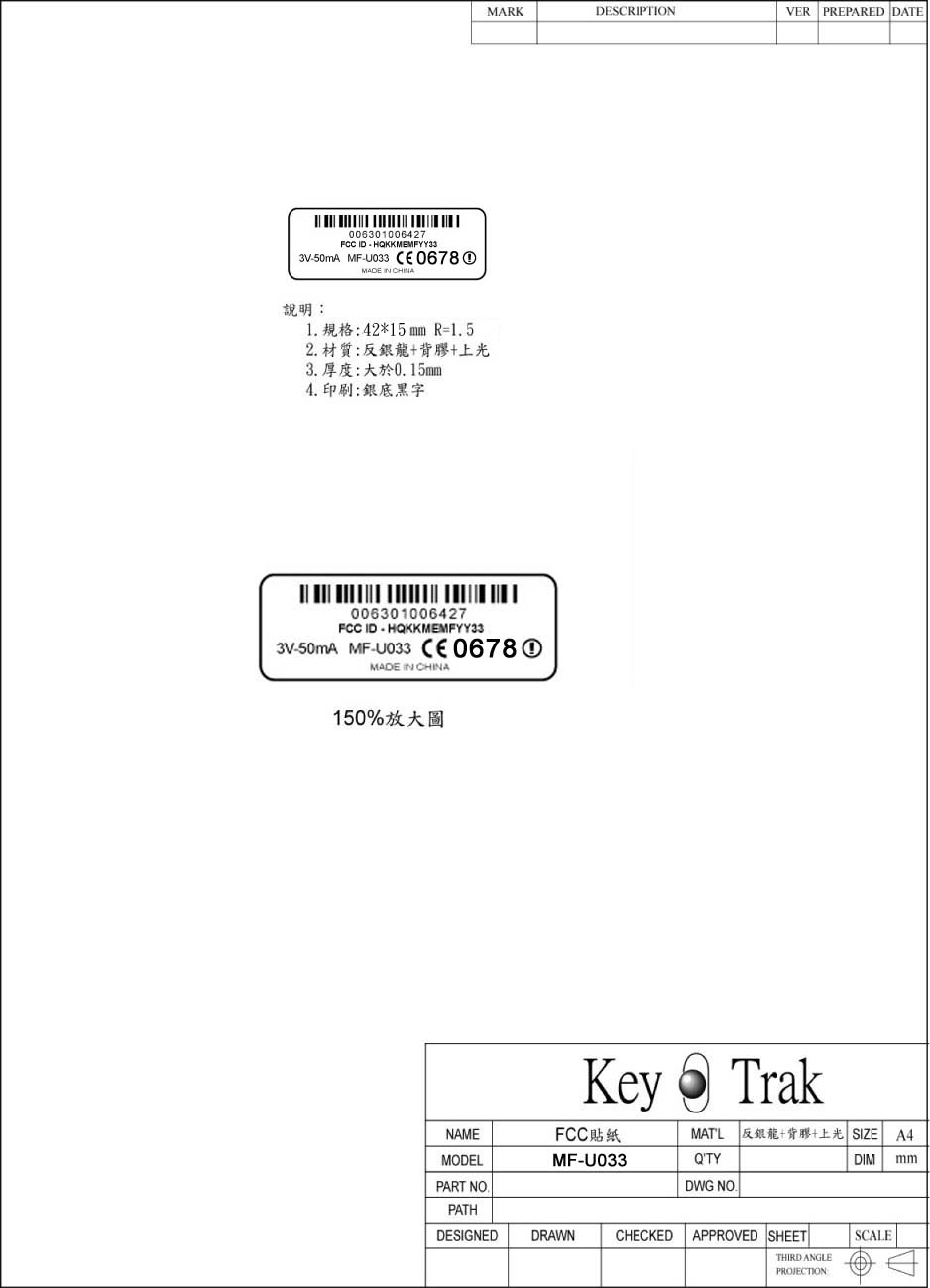
Document Text
Text extracted from the exhibit documents filed with the FCC. Open a document above to read the original.
Users Manual
RF Keyboard & Mouse User Manual PRODUCT LIST When you have opened the package, please make sure that all accessories are included as below: z Wireless Keyboard ×1 z Wireless Mouse ×1 z Receiver ×1 z Driver Disk ×1 z User’s instructional Guide ×1 z Alkaline Batteries of size AA ×3 (for keyboard) z Ni-MH Batteries of size AAA ×2 (for Mouse) In case of missing or damage of the above accessories, please contact your purchased dealer immediately. BATTERY INSTALLATION Open the battery cap , which is on keyboard’s or mouse’s reverse side , place batteries, and put the cap back. Every time after having changed batteries , please reset up mouse ,or keyboard, or mouse and keyboard depending on which unit you have changed batteries. For re-setup , please follow the setup of “SETUP FOR USE “. HARDWARE INSTALLATION Shut down your computer system. Connect the green connector of the receiver to the PS2 connection port of the computer , or connect the purple connector of the receiver to the PS2 connection port,or connect the black USB connector of the receiver to the USB connection port on the computer. Turn on your computer system. SOFTWARE INSTALLATION (DRIVER) Insert the CD/Driver into CD-ROM. The computer will into the setup up screen . Select “KEYBOARD + MOUSE 2 IN 1” Click on the appropriate item to setup. Follow the setups indicated in the screen to complete the setup. SETUP FOR USE 1. MOUSE 1.1 Aim the front point of the mouse at receiver. PRESS THE BUTTON ON THE REAR SIDE OF MOUSE AND RELEASE, THEN PRESS THE CONNECTOR BUTTON ON THE RECEIVER AND RELEASE WITHIN 15 SECONDS. Move the mouse and the cursor is moving then the setup of mouse is completed .If the cursor is not moving , please repeat the above setup. 2. KEYBOARD 2.1 PRESS THE BUTTON ON THE REAR SIDE OF KEYBOARD AND RELEASE, THEN PRESS THE CONNECTOR BUTTON ON THE RECEIVER AND RELEASE WITHIN 15 SECONDS. Press the “Num Lock “key ,you can find the Num indicator light of receiver is changing status. The setup of keyboard is completed. If not, please repeat the steps. MOUSE BUTTON FUNCTION SETUP 1. Get into setup from the control desk or directly click into the mouse pattern show in right-down corner of the screen . It shows the functions as following: Button : setup for habit of using right or left hand, adjustment of the speed of continuously pressing twice the mouse buttons, adjustment of numbers of column for each rolling. Mouse Marking : to set up the pattern or mouse marking. Wheel : to set up the functions of hot key, zooming ,and rolling of auto-turning. Motion : to set up the moving speed of mouse sign, the length of the dragging tail, and non-border, etc. 2. After the function is set u, press “Yes” to store the new setup. TROUBLESHOOTING If the mouse or keyboard doesn’t function well, please follow the steps below: 1. Check if the connector of USB or PS/2 port is well connected or not. 2. heck if the positive(+) and negative(-) pole of the battery is put correctly. If the power is low, the mouse will become sluggish or slow. 3. Reset: Follow the setup of “Setup for use”. HARDWARE MAINTENANCE AND CLEANING When the mouse doesn’t move smoothly or its speed is not normal, please clean the rolling ball of he mouse. The steps are as follows: 1. Follow the arrow direction (open with clockwise direction, and close with counterclockwise direction) to turn the rolling ball cap, which is under the mouse, to take out the ball. 2. Wipe the ball with a clean cloth dampen with clean water or alcohol, and wipe the dust inside the mouse with a dry clean cloth. After the cleaning is done, put back the ball and the cap. (Caution: never clean with organic dissolvent,) ENVIRONMENT To avoid environmental interference, which will reduce the effective distance, it should be noted below for the mouse and receiver: 1. Do not put the mouse and receiver on metal cabinet or metal desk. It’s better not having metal or interference source around, which affect the RF communication, and reduce the communication distance. 2. The ideal for the mouse and receiver is having 15-20 cm distant from computers or, in any open place. 3. Keep a distance of more than 1.5m to avoid interference if there are other RF devices in using. HOW TO REMOVE THE DRIVER -From the windows taskbar, click the Start, then select Setup, Control desk, Add/Remove program. Find the file USB wireless Mouse and click Add/Remove. -in the window Confirm File Deletion, click YES. For any problem in using this device, please reach to the Customer Service Center through the e-mail n the website. A response will be forwarded by e-mail to you very soon. This device complies with Part 15 of the FCC Rules. Operation is subject to the following two conditions:(1) this device may not cause harmful interference, and (2) this device must accept any interference received, including interference that may cause undesired operation. This equipment has been tested and found to comply with the limits for a Class B digital device, pursuant to Part 15 of the FCC Rules. These limits are designed to provide reasonable protection against harmful interference in a residential installation. This equipment generates, uses and can radiated radio frequency energy and, if not installed and used in accordance with the instructions, may cause harmful interference to radio communications. However, there is no guarantee that interference will not occur in a particular installation If this equipment does cause harmful interference to radio or television reception, which can be determined by turning the equipment off and on, the user is encouraged to try to correct the interference by one or more of the following measures: -Reorient or relocate the receiving antenna. -Increase the separation between the equipment and receiver. -Connect the equipment into an outlet on a circuit different from that to which the receiver is connected. -Consult the dealer or an experienced radio/TV technician for help. Changes or modifications not expressl…
Text truncated - open the document above for the full version.
Users Manual
RF Keyboard & Mouse User Manual PRODUCT LIST When you have opened the package, please make sure that all accessories are included as below: z Wireless Keyboard ×1 z Wireless Mouse ×1 z Receiver ×1 z Driver Disk ×1 z User’s instructional Guide ×1 z Alkaline Batteries of size AA ×3 (for keyboard) z Ni-MH Batteries of size AAA ×2 (for Mouse) In case of missing or damage of the above accessories, please contact your purchased dealer immediately. BATTERY INSTALLATION Open the battery cap , which is on keyboard’s or mouse’s reverse side , place batteries, and put the cap back. Every time after having changed batteries , please reset up mouse ,or keyboard, or mouse and keyboard depending on which unit you have changed batteries. For re-setup , please follow the setup of “SETUP FOR USE “. HARDWARE INSTALLATION Shut down your computer system. Connect the green connector of the receiver to the PS2 connection port of the computer , or connect the purple connector of the receiver to the PS2 connection port,or connect the black USB connector of the receiver to the USB connection port on the computer. Turn on your computer system. SOFTWARE INSTALLATION (DRIVER) Insert the CD/Driver into CD-ROM. The computer will into the setup up screen . Select “KEYBOARD + MOUSE 2 IN 1” Click on the appropriate item to setup. Follow the setups indicated in the screen to complete the setup. SETUP FOR USE 1. MOUSE 1.1 Aim the front point of the mouse at receiver. PRESS THE BUTTON ON THE REAR SIDE OF MOUSE AND RELEASE, THEN PRESS THE CONNECTOR BUTTON ON THE RECEIVER AND RELEASE WITHIN 15 SECONDS. Move the mouse and the cursor is moving then the setup of mouse is completed .If the cursor is not moving , please repeat the above setup. 2. KEYBOARD 2.1 PRESS THE BUTTON ON THE REAR SIDE OF KEYBOARD AND RELEASE, THEN PRESS THE CONNECTOR BUTTON ON THE RECEIVER AND RELEASE WITHIN 15 SECONDS. Press the “Num Lock “key ,you can find the Num indicator light of receiver is changing status. The setup of keyboard is completed. If not, please repeat the steps. MOUSE BUTTON FUNCTION SETUP 1. Get into setup from the control desk or directly click into the mouse pattern show in right-down corner of the screen . It shows the functions as following: Button : setup for habit of using right or left hand, adjustment of the speed of continuously pressing twice the mouse buttons, adjustment of numbers of column for each rolling. Mouse Marking : to set up the pattern or mouse marking. Wheel : to set up the functions of hot key, zooming ,and rolling of auto-turning. Motion : to set up the moving speed of mouse sign, the length of the dragging tail, and non-border, etc. 2. After the function is set u, press “Yes” to store the new setup. TROUBLESHOOTING If the mouse or keyboard doesn’t function well, please follow the steps below: 1. Check if the connector of USB or PS/2 port is well connected or not. 2. heck if the positive(+) and negative(-) pole of the battery is put correctly. If the power is low, the mouse will become sluggish or slow. 3. Reset: Follow the setup of “Setup for use”. HARDWARE MAINTENANCE AND CLEANING When the mouse doesn’t move smoothly or its speed is not normal, please clean the rolling ball of he mouse. The steps are as follows: 1. Follow the arrow direction (open with clockwise direction, and close with counterclockwise direction) to turn the rolling ball cap, which is under the mouse, to take out the ball. 2. Wipe the ball with a clean cloth dampen with clean water or alcohol, and wipe the dust inside the mouse with a dry clean cloth. After the cleaning is done, put back the ball and the cap. (Caution: never clean with organic dissolvent,) ENVIRONMENT To avoid environmental interference, which will reduce the effective distance, it should be noted below for the mouse and receiver: 1. Do not put the mouse and receiver on metal cabinet or metal desk. It’s better not having metal or interference source around, which affect the RF communication, and reduce the communication distance. 2. The ideal for the mouse and receiver is having 15-20 cm distant from computers or, in any open place. 3. Keep a distance of more than 1.5m to avoid interference if there are other RF devices in using. HOW TO REMOVE THE DRIVER -From the windows taskbar, click the Start, then select Setup, Control desk, Add/Remove program. Find the file USB wireless Mouse and click Add/Remove. -in the window Confirm File Deletion, click YES. For any problem in using this device, please reach to the Customer Service Center through the e-mail n the website. A response will be forwarded by e-mail to you very soon. This device complies with Part 15 of the FCC Rules. Operation is subject to the following two conditions:(1) this device may not cause harmful interference, and (2) this device must accept any interference received, including interference that may cause undesired operation. This equipment has been tested and found to comply with the limits for a Class B digital device, pursuant to Part 15 of the FCC Rules. These limits are designed to provide reasonable protection against harmful interference in a residential installation. This equipment generates, uses and can radiated radio frequency energy and, if not installed and used in accordance with the instructions, may cause harmful interference to radio communications. However, there is no guarantee that interference will not occur in a particular installation If this equipment does cause harmful interference to radio or television reception, which can be determined by turning the equipment off and on, the user is encouraged to try to correct the interference by one or more of the following measures: -Reorient or relocate the receiving antenna. -Increase the separation between the equipment and receiver. -Connect the equipment into an outlet on a circuit different from that to which the receiver is connected. -Consult the dealer or an experienced radio/TV technician for help. Changes or modifications not expressl…
Text truncated - open the document above for the full version.
Cover Letter(s)
Key Mouse Electronic Enterprise Co., Ltd. April 27, 2004 Federal Communications Commission Authorization and Evaluation Division FCC ID:HQKKMEKFYY33 Confidentiality Request Pursuant to Sections 0..457 and 0.459 of the Commission’s Rules, the Applicant Hereby requests confidential treatment of information accomparrting this Application As outlined below: 1. Block diagram 2. Circuits diagram 3. Operation description 4. Parts List The above materials contain trade secrets and proprietary information not customarily Released to the public. The public disclosure of these matters might be harmful to the Applicant and provide unjustified benefits to its competitors. The Applicant understands that pursuant to Rule 0.457, disclosure of this Application and all accompanying documentation will not be made before the date of the Grant for this application Sincerely, Shu Min Hung/ Audit Specialist Applicant: Key Mouse Electronic Enterprise Co., Ltd. Address: Rm. No.602, 6F-8, No.3, Wu-Chuan 1 st Rd. Hsin Chuang City, Taipei, Taiwan R.O.C. TEL: 886-2-2298-2929 FAX: 886-2-2298-2978 E-Mail: [email protected]
External Photos
FCC TEST REPORT REPORT NO. : F3D1007 SPORTON International Inc. PAGE NUMBER : A1 OF A8 TEL : 886-2-2696-2468 ISSUED DATE : Dec. 20, 2003 FAX : 886-2-2696-2255 APPENDIX A. Photographs of EUT FCC TEST REPORT REPORT NO. : F3D1007 SPORTON International Inc. PAGE NUMBER : A2 OF A8 TEL : 886-2-2696-2468 ISSUED DATE : Dec. 20, 2003 FAX : 886-2-2696-2255
External Photos
FCC TEST REPORT REPORT NO. : F3D1007 SPORTON International Inc. PAGE NUMBER : A1 OF A8 TEL : 886-2-2696-2468 ISSUED DATE : Dec. 20, 2003 FAX : 886-2-2696-2255 APPENDIX A. Photographs of EUT FCC TEST REPORT REPORT NO. : F3D1007 SPORTON International Inc. PAGE NUMBER : A2 OF A8 TEL : 886-2-2696-2468 ISSUED DATE : Dec. 20, 2003 FAX : 886-2-2696-2255
Internal Photos
FCC TEST REPORT REPORT NO. : F3D1007 SPORTON International Inc. PAGE NUMBER : A3 OF A8 TEL : 886-2-2696-2468 ISSUED DATE : Dec. 20, 2003 FAX : 886-2-2696-2255 FCC TEST REPORT REPORT NO. : F3D1007 SPORTON International Inc. PAGE NUMBER : A4 OF A8 TEL : 886-2-2696-2468 ISSUED DATE : Dec. 20, 2003 FAX : 886-2-2696-2255 FCC TEST REPORT REPORT NO. : F3D1007 SPORTON International Inc. PAGE NUMBER : A5 OF A8 TEL : 886-2-2696-2468 ISSUED DATE : Dec. 20, 2003 FAX : 886-2-2696-2255 FCC TEST REPORT REPORT NO. : F3D1007 SPORTON International Inc. PAGE NUMBER : A6 OF A8 TEL : 886-2-2696-2468 ISSUED DATE : Dec. 20, 2003 FAX : 886-2-2696-2255 FCC TEST REPORT REPORT NO. : F3D1007 SPORTON International Inc. PAGE NUMBER : A7 OF A8 TEL : 886-2-2696-2468 ISSUED DATE : Dec. 20, 2003 FAX : 886-2-2696-2255 FCC TEST REPORT REPORT NO. : F3D1007 SPORTON International Inc. PAGE NUMBER : A8 OF A8 TEL : 886-2-2696-2468 ISSUED DATE : Dec. 20, 2003 FAX : 886-2-2696-2255
Internal Photos
FCC TEST REPORT REPORT NO. : F3D1007 SPORTON International Inc. PAGE NUMBER : A3 OF A8 TEL : 886-2-2696-2468 ISSUED DATE : Dec. 20, 2003 FAX : 886-2-2696-2255 FCC TEST REPORT REPORT NO. : F3D1007 SPORTON International Inc. PAGE NUMBER : A4 OF A8 TEL : 886-2-2696-2468 ISSUED DATE : Dec. 20, 2003 FAX : 886-2-2696-2255 FCC TEST REPORT REPORT NO. : F3D1007 SPORTON International Inc. PAGE NUMBER : A5 OF A8 TEL : 886-2-2696-2468 ISSUED DATE : Dec. 20, 2003 FAX : 886-2-2696-2255 FCC TEST REPORT REPORT NO. : F3D1007 SPORTON International Inc. PAGE NUMBER : A6 OF A8 TEL : 886-2-2696-2468 ISSUED DATE : Dec. 20, 2003 FAX : 886-2-2696-2255 FCC TEST REPORT REPORT NO. : F3D1007 SPORTON International Inc. PAGE NUMBER : A7 OF A8 TEL : 886-2-2696-2468 ISSUED DATE : Dec. 20, 2003 FAX : 886-2-2696-2255 FCC TEST REPORT REPORT NO. : F3D1007 SPORTON International Inc. PAGE NUMBER : A8 OF A8 TEL : 886-2-2696-2468 ISSUED DATE : Dec. 20, 2003 FAX : 886-2-2696-2255
Test Report
FCC TEST REPORT Report No. : F3D1007 SPORTON International Inc. TEL : 886-2-2696-2468 FAX : 886-2-2696-2255 FCC TEST REPORT for 47 CFR, Part 15, Subpart C Equipment : RF Mouse Model No. : Mx-yy33/35/36; (x=F,G,O; y=0~9; A~Z) FCC ID : HQKKMEMFYY33 Filing Type : Certification Applicant : Key Mouse Electronic Enterprise Co., Ltd. Rm. No. 602, 6F-8, No. 3, Wu-Chuan 1 st Rd., Hsin-Chuang City, Ta i p e i , Ta i w a n , R . O . C . . The test result refers exclusively to the test presented test model / sample. Without written approval of SPORTON International Inc., the test report shall not be reproduced except in full. Certificate or Test Report must not be used by the applicant to claim the product in this test report endorsement by NVLAP or any agency of U.S. government. SPORTON International Inc. 6F, No.106, Sec. 1, Hsin Tai Wu Rd., Hsi Chih, Taipei Hsien, Taiwan, R.O.C. FCC TEST REPORT Report No. : F3D1007 SPORTON International Inc. FCC ID : HQKKMEMFYY33 TEL : 886-2-2696-2468 Page No. : i FAX : 886-2-2696-2255 Issued Date : Dec. 20, 2003 Table of Contents History of this test report....................................................................................................................................ii CERTIFICATE OF COMPLIANCE........................................................................................................................1 1. General Description of Equipment under Test.............................................................................................2 1.1. Applicant..........................................................................................................................................................................................2 1.2. Manufacturer ...................................................................................................................................................................................2 1.3. Basic Description of Equipment under Test ....................................................................................................................................2 1.4. Feature of Equipment under Test ...................................................................................................................................................3 2. Test Configuration of Equipment under Test ...............................................................................................4 2.1. Test Manner ....................................................................................................................................................................................4 2.2. Description of Test System .............................................................................................................................................................4 2.3. Connection Diagram of Test System ..............................................................................................................................................5 2.4. Band edge compliance plot per 15.227(b). .....................................................................................................................................6 3. Test Software ...................................................................................................................................................8 4. General Information of Test............................................................................................................................9 4.1. Test Facility .....................................................................................................................................................................................9 4.2. Test Voltage ....................................................................................................................................................................................9 4.3. Standard for Methods of Measurement...........................................................................................................................................9 4.4. Frequency Range Investigated .......................................................................................................................................................9 4.5. Frequency Range Investigated .......................................................................................................................................................9 4.6. Test Distance ..................................................................................................................................................................................9 5. Test of Conducted Powerline .......................................................................................................................10 6. Test of Radiated Emission............................................................................................................................11 6.1. Major Measuring Instruments........................................................................................................................................................11 6.2. Test Procedures ............................................................................................................................................................................12 6.3. Typical Test Setup Layout of Radiated Emission..........................................................................................................................13 6.4. Test Result of Radiated Emission .................................................................................................................................................14 7. EMI Suppression Component List ...............................................................................................................19 8. Antenna Factor & Cable Loss ..................................................................................................…
Text truncated - open the document above for the full version.
Test Report
FCC TEST REPORT Report No. : F3D1007 SPORTON International Inc. TEL : 886-2-2696-2468 FAX : 886-2-2696-2255 FCC TEST REPORT for 47 CFR, Part 15, Subpart C Equipment : RF Mouse Model No. : Mx-yy33/35/36; (x=F,G,O; y=0~9; A~Z) FCC ID : HQKKMEMFYY33 Filing Type : Certification Applicant : Key Mouse Electronic Enterprise Co., Ltd. Rm. No. 602, 6F-8, No. 3, Wu-Chuan 1 st Rd., Hsin-Chuang City, Ta i p e i , Ta i w a n , R . O . C . . The test result refers exclusively to the test presented test model / sample. Without written approval of SPORTON International Inc., the test report shall not be reproduced except in full. Certificate or Test Report must not be used by the applicant to claim the product in this test report endorsement by NVLAP or any agency of U.S. government. SPORTON International Inc. 6F, No.106, Sec. 1, Hsin Tai Wu Rd., Hsi Chih, Taipei Hsien, Taiwan, R.O.C. FCC TEST REPORT Report No. : F3D1007 SPORTON International Inc. FCC ID : HQKKMEMFYY33 TEL : 886-2-2696-2468 Page No. : i FAX : 886-2-2696-2255 Issued Date : Dec. 20, 2003 Table of Contents History of this test report....................................................................................................................................ii CERTIFICATE OF COMPLIANCE........................................................................................................................1 1. General Description of Equipment under Test.............................................................................................2 1.1. Applicant..........................................................................................................................................................................................2 1.2. Manufacturer ...................................................................................................................................................................................2 1.3. Basic Description of Equipment under Test ....................................................................................................................................2 1.4. Feature of Equipment under Test ...................................................................................................................................................3 2. Test Configuration of Equipment under Test ...............................................................................................4 2.1. Test Manner ....................................................................................................................................................................................4 2.2. Description of Test System .............................................................................................................................................................4 2.3. Connection Diagram of Test System ..............................................................................................................................................5 2.4. Band edge compliance plot per 15.227(b). .....................................................................................................................................6 3. Test Software ...................................................................................................................................................8 4. General Information of Test............................................................................................................................9 4.1. Test Facility .....................................................................................................................................................................................9 4.2. Test Voltage ....................................................................................................................................................................................9 4.3. Standard for Methods of Measurement...........................................................................................................................................9 4.4. Frequency Range Investigated .......................................................................................................................................................9 4.5. Frequency Range Investigated .......................................................................................................................................................9 4.6. Test Distance ..................................................................................................................................................................................9 5. Test of Conducted Powerline .......................................................................................................................10 6. Test of Radiated Emission............................................................................................................................11 6.1. Major Measuring Instruments........................................................................................................................................................11 6.2. Test Procedures ............................................................................................................................................................................12 6.3. Typical Test Setup Layout of Radiated Emission..........................................................................................................................13 6.4. Test Result of Radiated Emission .................................................................................................................................................14 7. EMI Suppression Component List ...............................................................................................................19 8. Antenna Factor & Cable Loss ..................................................................................................…
Text truncated - open the document above for the full version.
Test Setup Photos
FCC TEST REPORT Report No. : F3D1007 SPORTON International Inc. Page No. : B1 of B2 TEL : 886-2-2696-2468 Issued Date : Dec. 20, 2003 FAX : 886-2-2696-2255 Photographs of Radiated Emission Test Configuration FRONT VIEW APPENDIX B. Photographs of Setup FCC TEST REPORT Report No. : F3D1007 SPORTON International Inc. Page No. : B2 of B2 TEL : 886-2-2696-2468 Issued Date : Dec. 20, 2003 FAX : 886-2-2696-2255 REAR VIEW
Test Setup Photos
FCC TEST REPORT Report No. : F3D1007 SPORTON International Inc. Page No. : B1 of B2 TEL : 886-2-2696-2468 Issued Date : Dec. 20, 2003 FAX : 886-2-2696-2255 Photographs of Radiated Emission Test Configuration FRONT VIEW APPENDIX B. Photographs of Setup FCC TEST REPORT Report No. : F3D1007 SPORTON International Inc. Page No. : B2 of B2 TEL : 886-2-2696-2468 Issued Date : Dec. 20, 2003 FAX : 886-2-2696-2255 REAR VIEW
Contact Information
Applicant
MS. Hingis Chen(Manager)
Test Firm
SPORTON International IncKathy Lin
Technical Specifications
| # | Rule Parts | Frequency Range | Power Output |
|---|---|---|---|
| 1 | 15C | 26.96 MHz - 27.28 MHz | - |
Other Applications from Key Mouse Electronic Enterprise Co Ltd

HQKKMEKA3381J
Apr 06, 2010Wireless Keyboard
Equipment Class
DXX - Part 15 Low Power Communication Device Transmitter
HQKKMEMAC233J
Apr 06, 2010Wireless Mouse
Equipment Class
DXX - Part 15 Low Power Communication Device Transmitter
HQKKMERGG5J
Apr 06, 2010Wireless Dongle
Equipment Class
DXX - Part 15 Low Power Communication Device Transmitter
HQKKMEMYX138
May 09, 200527 MHz Wireless Mouse
Equipment Class
DXX - Part 15 Low Power Communication Device Transmitter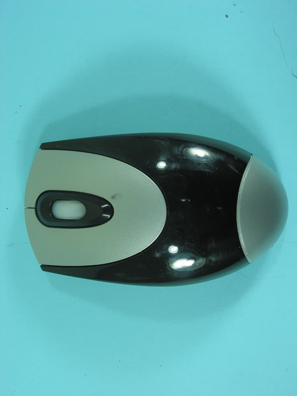
HQKKMEMFB033
Apr 20, 200527MHz Wireless Mouse
Equipment Class
DXX - Part 15 Low Power Communication Device Transmitter