I32TA-7410Aeronautical Ground Station
TAC Systems Inc
Click to zoom
Application Details
- Equipment Class
- TNB - Licensed Non-Broadcast Station Transmitter
- Date of Grant
- Jul 10, 2000
- Application Purpose
- Original Equipment
- Date of Application
- Jul 10, 2000
- Equipment Note
- Aeronautical Ground Station
- Frequency Range
- 118.00000000 - 137.00000000
- Company
- TAC Systems Inc
- Country
- United States
Documents & Files
Document Text
Text extracted from the exhibit documents filed with the FCC. Open a document above to read the original.
Cover Letter(s)
May 24, 2000 FEDERAL AVIATION ADMINISTRATION Spectrum Engineering Division 800 Independence Avenue S.W. Washington, DC 20591 Ref (a): Tac Systems, Inc. FCC ID: I32TA-7410, I32TA-7425 and I32TA-7450 (b): FCC Rules part 87.147(d) To Whom It May Concern: The applications for the approval of Tac Systems, Inc. FCC ID: I32TA-7410, I32TA-7425 and I32TA-7450 will be submitted to the Federal Communicatio ns Commission upo n completion of the test reports. Our laboratory tested these devices in accordance with the FCC rules part 87 and found that they comply with the necessary requirements. Specifications are listed below: I32TA-7410I32TA-7425I32TA-7450 Frequency Range: 118-137MHz118-137MHz118-137MHz Rated RF Power Output in Watts: 102550 Frequency Tolerance: 202020 Emission Designator: 6K00A3E6K00A3E6K00A3E Antenna Characteristics: ExternalExternalExternal Please send a reply to this notification to: Eric F. Dobson TIMCO ENGINEERING, INC. P.O. Box 370 Newberry, FL 32669 Should you have any questio ns, please feel free to contact us. Regards, ERIC F. DOBSON TAC SYSTEMS INC. FCC ID : I32TA-7410 JOB # 160U0 EXHIBIT # 1
RF Exposure Info
SYSTEM DESCRIPTION 1.0 IMPORTANT NOTE ON ANTENNA INSTALLATION: To comply with FCC RF exposure compliance requirements, the following antenna installation and device operating configurations must be satisfied; 1. The antenna MUST be fixed-mounted on an outdoor permanent structure with a separation distance of at least 6 meters from all persons during normal operation. 2. If the antenna is co-located, then its installation must meet the guidelines in CFR PART §1.1037(B)(3 ) reprinted below for your reference. CFR PART §1.1037(B)(3) In general when the guidelines specified in §1.1310 are exceeded in an accessible area due to the emissions form multiple fixed transmitters, actions necessary to bring the area into compliance are the shares responsibility of all licensees whose transmitters produce, at the area in question, power density levels that exceed 5% of the power density exposure limit applicable to their particular transmitter or field strength levels that, when squared, exceed 5% of the square of the electric or magnetic fields strength limit applicable to their particular transmitter. Owners of transmitter sites are expected to allow applicants and licensees to take reasonable steps to comply with the requirements contained in §1.1307 (b) and, where feasible, should encourage co-location of transmitters and common solutions for controlling access to areas where the RF exposure limits contained in §1.1310 might be exceeded. DRAFT TAC SYSTEMS INC. FCC ID: I32TA-7410 JOB # 160U0 EXHIBIT # 16A
Test Report
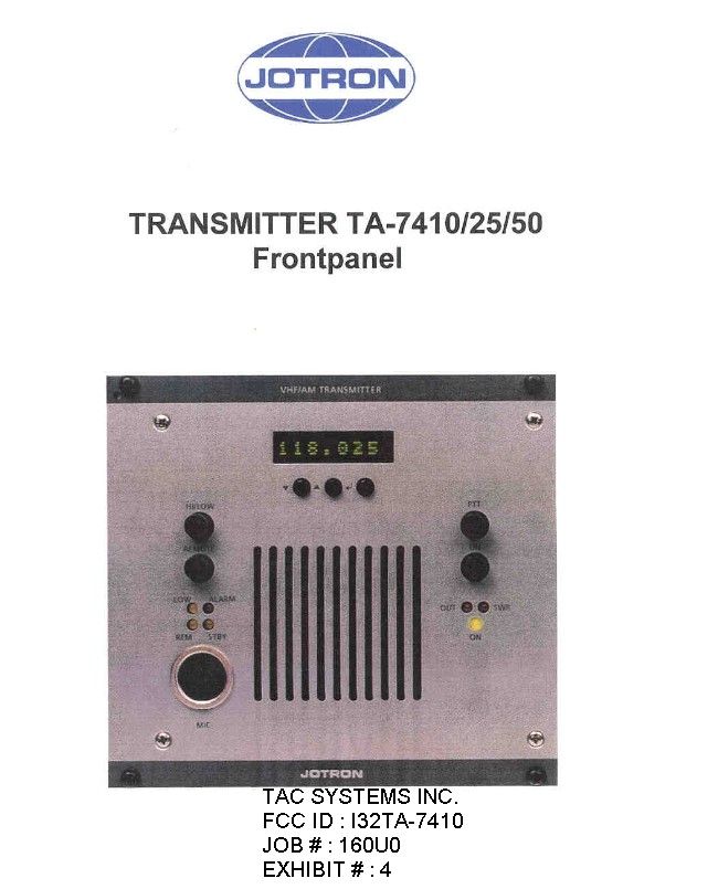
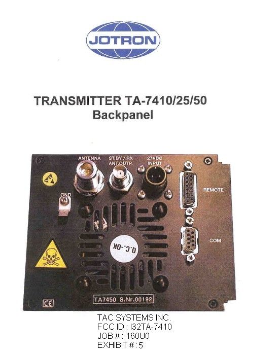
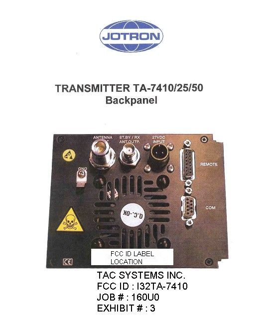
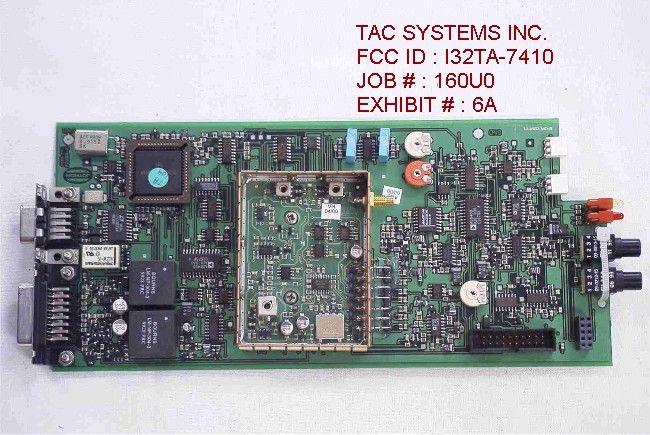
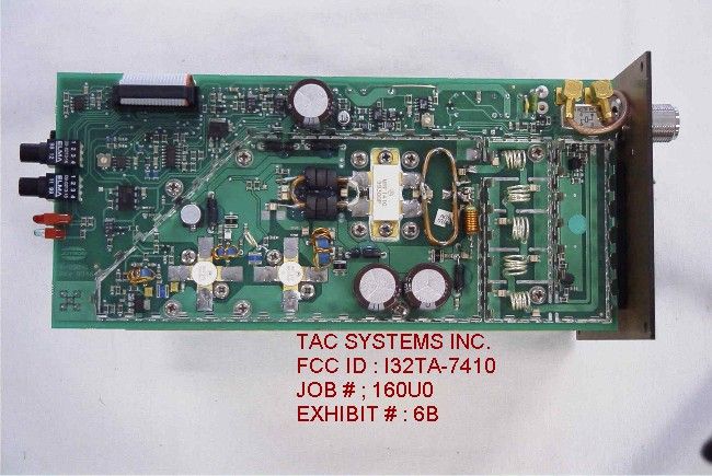
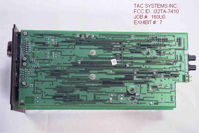
TABLE OF CONTENTS LIST APPLICANT: TAC SYSTEMS INC. FCC ID: I32TA-7410 TEST REPORT: PAGE 1......GENERAL INFORMATION & TECHNICAL DESCRIPTION PAGE 2......TECHNICAL DESCRIPTION CONT'D AND MODULATION CHARAC. PAGE 3......OCCUPIED BANDWIDTH DATA PAGE 4......SPURIOUS EMISSIONS & METHOD OF MEASUREMENT PAGE 5......RADIATED SPURIOUS EMISSIONS PAGE 6......METHOD OF MEASURING RADIATED SPURIOUS EMISSIONS PAGE 7......FREQUENCY STABILITY PAGE 8......TEST EQUIPMENT LIST EXHIBIT CONTAINING: EXHIBIT 1.........FAA LETTER EXHIBIT 2.........FCC ID LABEL SAMPLE EXHIBIT 3.........FCC ID LABEL LOCATION EXHIBIT 4.........EXTERNAL PHOTO FRONT VIEW EXHIBIT 5.........EXTERNAL PHOTO REAR VIEW EXHIBIT 6A........INTERNAL PHOTO COMPONENT -EXCITER/MODULATOR EXHIBIT 6B........INTERNAL PHOTO COMPONENT -POWER AMPLIFIER 10W EXHIBIT 7.........INTERNAL PHOTO COPPER SIDE -EXCITER/MODULATOR EXHIBIT 8.........BLOCK DIAGRAM EXHIBIT 9.........CIRCUIT DIAGRAM RF BOARD-1 of 3 EXHIBIT 10........CIRCUIT DIAGRAM RF BOARD-2 of 3 EXHIBIT 11........CIRCUIT DIAGRAM RF BOARD-3 of 3 EXHIBIT 12........CIRCUIT DIAGRAM SYNTHESIZER UNIT EXHIBIT 13........CIRCUIT DIAGRAM LF BOARD-1 of 3 EXHIBIT 14........CIRCUIT DIAGRAM LF BOARD-2 of 3 EXHIBIT 15........CIRCUIT DIAGRAM LF BOARD-3 of 3 EXHIBIT 16A.......ANTENNA NOTICE & INSTALLATION INSTRUCTIONS EXHIBIT 16B-C.....SYSTEM DESCRIPTION EXHIBIT 17A-I.....FUNCTIONAL DESCRIPTION EXHIBIT 18A-R.....OPERATING INSTRUCTIONS EXHIBIT 19........TUNING PROCDURE EXHIBIT 20A-F.....TECHNICAL DESCRIPTION EXHIBIT 21........AUDIO FREQUENCY RESPONSE PLOT EXHIBIT 22........MODULATION LIMITING PLOT - 300 Hz EXHIBIT 23........MODULATION LIMITING PLOT - 1000 Hz EXHIBIT 24........MODUALTION LIMITING PLOT - 3000 Hz EXHIBIT 25A-25B...OCCUPIED BANDWIDTH PLOTS APPLICANT : TAC SYSTEMS INC. FCC ID : I32TA-7410 DATE : 22 May 2000 REPORT # : T:\CUS\T\TAC\TAC160U0\160U0.RPT TABLE OF CONTENTS GENERAL INFORMATION REQUIRED FOR TYPE ACCEPTANCE 2.1033(c)(1)(2) TAC SYSTEMS INC. will sell their FCC ID: I32TA-7410 in quantity, for use under FCC RULES PART 87, AERONAUTICAL GROUND STATION. This UUT has an antenna connector. TAC SYSTEMS INC. PO Box 705 Coconut Grove, Florida 33222-0705 2.1033(c)(3) Instruction book. The instruction manual is included as Exhibit # 18A-18R. 2.1033(c)(4) TECHNICAL DESCRIPTION (4) Type of Emission: 6K00A3E ALLOWED AUTHORIZED BANDWIDTH = 25KHz. Frequency Range: Part 87: 118-137MHz, TEST FREQ = 127.000MHz. (5) Power Range and Controls:The output of this UNIT is NOT adjustable. (6)(7) Maximum Output Power Rating: 10.0 Watt average power into 50 ohms resistive load. (8) DC Voltages and Current into Final Amplifier: FINAL AMPLIFIER ONLY 27.0VDC Vce = 27.0Volts Ice = 1.54A. (9) Tune-up procedure. The tune-up procedure is given as Exhibit # 19 2.1033(c)(10) Complete Circuit Diagrams: The circuit diagram is included as Exhibit #: 9-15. The block diagram is also included as Exhibit #: 8. 2.1033(c)(11) The equipment identification is shown as Exhibit No. 2. 2.1033(c)(12) Photographs of the equipment are shown as Exhibits No. 4-7. 2.1033(c)(13) Equipment employing Digital modulation. DATE: 22 May 2000 REPORT #: T:\CUS\T\TAC\TAC160U0\160U0.RPT PAGE #: 1 TECHNICAL DESCRIPTION CONT'D 2.1033(c)(14) The data required by 2.1046 through 2.1057 follows; 2.1046 Limiting Power: There is no provision for limiting power, the design limits the power to 10Watts. There is NO provision for reducing the power. 2.1047 Modulation Characteristics: The transmitter audio circuitry is contained in the audio processing board and is controlled by that assembly dependent upon which combination of modulation. The audio frequency response is attached as Exhibit #21 and the modulation limiting plots are attached as Exhibits #22-24. The audio frequency response was measured in accordance with TIA/EIA Specification 603 Paragraph 2.2.6. 87.141 AUDIO LOW PASS FILTER The audio low pass filter is not required in this unit. APPLICANT : TAC SYSTEMS INC. FCC ID : I32TA-7410 REPORT # : T:\CUS\T\TAC\TAC160U0\160U0.RPT PAGE # : 2 APPLICANT : TAC SYSTEMS INC. FCC ID : I32TA-7410 OCCUPIED BANDWIDTH 2.1049 Occupied bandwidth: Data in the plots shows that frequencies removed from the assigned frequency by more than 50%(12.5KHz) up to and including 100% percent of the authorized bandwidth the attenuation must be at least 25dB. When the frequency is removed from the assigned frequency by more that 100% up to and including 250% of the authorized bandwidth the attenua- tion must be at least 35dB. When the frequency is removed from the assigned frequency by more than 250% of the author- ized bandwidth the attenuation must be at least 43 + log pY dB. The plots show the transmitter modulated with 2500 Hz(the highest modulation frequency), adjusted for 50% modulation plus 16dB. The spectrum analyzer was set with the unmodulated carrier at the top of the screen. The test procedure diagram and occupied bandwidth plots follow. Microphone transmitter Test procedure diagram OCCUPIED BANDWIDTH MEASUREMENT /------------\ Coupler /------------\ | | /----\ | | | Transmitter|------------|____|------|__ 50 ohm | | under test | \----/ | Resistive| \------------/ | | Load | | | \------------/ /------------\ /-----------\ | Audio | | Spectrum | | Oscillator | | Analyzer | | | \-----------/ \------------/ APPLICANT: TAC SYSTEMS INC. FCC ID: I32TA-7410 DATE: 22 May 2000 REPORT #: T:\CUS\T\TAC\TAC160U0\160U0.RPT PAGE #: 3 SPURIOUS EMISSIONS AND METHOD OF MEASUREMENT 2.1051 Spurious emissions at antenna terminals(conducted): Data on the following page shows the level of conducted spurious responses. The carrier was modulated 90% using a 2500Hz tone. The spectrum was scanned from 30 to at least the 10th harmonic of the fundamental. Method of Measuring Conducted Spurious Emissions /---------\ |HP | |Spectrum | |Analyzer | |8566B | \---------/ /------------\ /-----------------\ /-----------\ | | | | | | | | |TRANSMITTER |------| 50 OHM RESISTIVE|----| ATTENUATOR|-----/ | UNDER TEST | | ATTENUATOR | …
Text truncated - open the document above for the full version.
Test Report
Modulation Limiting TAC Systems Inc. I32TA- 7410 0 20 40 60 80 100 00.20.40.60.8 rms Volts % Modulation 300 Hz TAC SYSTEMS INC. FCC ID: I32TA-7410 JOB # 160U0 EXHIBIT # 22
Test Report
Modulation Limiting TAC Systems Inc. I32TA-7410 0 10 20 30 40 50 60 70 80 90 00.0040.0080.012 rms Volts %Modulation 1000 Hz TAC SYSTEMS INC. FCC ID: I32TA-7410 JOB # 160U0 EXHIBIT # 23
Test Report
Modulation Limiting TAC Systems Inc. I32TA-7410 30 40 50 60 70 80 90 0.00550.0060.00650.0070.0075 rms Volts Deviation 3000 Hz TAC SYSTEMS INC. FCC ID : I32TA-7410 JOB # : 160U0 EXHIBIT # : 24
Contact Information
Applicant
Thomas A Coleman
Technical Specifications
| # | Rule Parts | Frequency Range | Power Output | Emission | Tolerance |
|---|---|---|---|---|---|
| 1 | 87 | 118 MHz - 137 MHz | 10 W | 6K00A3E | 0.0020000000 % |
Other Applications from TAC Systems Inc

I32TA-7450
Sep 07, 2000Aeronautical Ground Station
Equipment Class
TNB - Licensed Non-Broadcast Station Transmitter
I32TA-7425
Jul 10, 2000Aeronautical Ground Station
Equipment Class
TNB - Licensed Non-Broadcast Station TransmitterI32TA-7310
Apr 08, 1997TNB - Licensed Non-Broadcast Station Transmitter
Equipment Class
TNB - Licensed Non-Broadcast Station TransmitterI32RA-7201
Aug 13, 1996Aircraft Radio Receiver
Equipment Class
CXX - Communications Rcvr for use w/ licensed Tx and CBsI32TA-5302
May 06, 1991TNB - Licensed Non-Broadcast Station Transmitter
Equipment Class
TNB - Licensed Non-Broadcast Station Transmitter