I4OSE700Ship Station Marine Transceiver
Shakespeare Company, LLC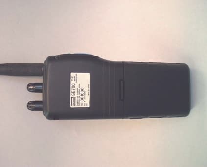
Click to zoom
Application Details
- Equipment Class
- TNF - Licensed Non-Broadcast Transmitter Held to Face
- Date of Grant
- Feb 15, 2000
- Application Purpose
- Original Equipment
- Date of Application
- Nov 17, 1999
- Equipment Note
- Ship Station Marine Transceiver
- Frequency Range
- 156.00000000 - 163.00000000
- Company
- Shakespeare Company, LLC
- Country
- United States
Documents & Files
Document Text
Text extracted from the exhibit documents filed with the FCC. Open a document above to read the original.
Users Manual
SE700 HAND HELD MARINE VHF RADIO OWNER’S HANDBOOK - 1 - TABLE OF CONTENS 1.0INTRODUCTION 2.0 INSTALLATION 3.0OPERATION 4.0APPENDIX - 2 - Figure1 Shakespeare SE700 Handheld Marine VHF Radio 1.0 INTRODUCTION 1.1 Purpose 1.2 Equipment Description 1.3 Supplied Parts 1.4 License - 3 - 2.0 INSTALLATION 2.1 Unpacking And Inspection 2.2 Preparation for Use 2.3 Antenna Installation 2.4 Battery Pack Installation 2.5 Charging the Battery 2.6 Using the Belt Clip 3.0 OPERATION 3.1 INTRODUCTION 5 1 2 3 4 - 4 - 1, Light key & Lock key2,PTT key 3, Squelch Knob4,Power Switch & Volume Control 5, External Charge Jack 3.2 Controls And Display 3.2.1 Controls (1)ON / OFF Volume Switch Turns power OFF if turned fully CCW. Max audio output if turned fully CW. All stored memory will be cleared by pressing “MEM” key and turning the power ON. LCD display test mode will be activated by pressing “Light” key and “16/9” key at the same time and turning the power ON. Display when the power is turned ON. Freq. Mode : Last used CH freq. mode. ( USA, INT, CANADA) Channel : 16CH, Working CH WX Channel :Last used WX CH. Tx Power :HI 5W LCD : All characters displayed for 2 sec. (2)Squelch Knob Squelch will get shallow when the knob is turned CCW. Squelch will get deep when turned CW. (3)Light Key By pressing the Light key, Alarm 1 will sound and back light will get ON or OFF. If pressed and held for 1.5 sec., alarm 1 will sound and all key operation will be locked. ( Key lock ) (4)PTT Key Radio will Tx when pressed. When it is on either WX CH or Non-Tx CH, Alarm 2 will sound and does not Tx. When the radio is transmitting for continuous 5 min., radio will stop Tx and Alarm 2 will sound until the PTT key is released. (5)SCAN Key If pressed, alarm 1 will sound and starts or ends ALL SCAN. Except in SCAN MODE, radio will start SCAN if the button is pressed ( short press or long press. ). Short press during SCAN mode will pause SCAN and cancel SCAN mode. SCAN mode will also be canceled if keys other than LIGHT key is pressed. After cancellation of SCAN mode, the radio will operate on the channel that the SCAN mode was cancelled. A long press during the SCAN mode will stop ALL scan and alarm 1 will sound and starts DW. A short press during memory stand-by will start Memory scan. Type of SCAN (a) ALL SCAN : Scans all the channels. (b) MEM-SCAN : Scans memory channels. - 5 - If only 1 or less channel is stored in memory, alarm 2 will sound and return to the previous operation . (6)MEM Key At a short press, alarm 1 will sound and starts memory stand-by. If pressed again, then it will show the channels stored in memory on the small CH display. It will show from the smallest number. Other channels stored in memory can be seen by pressing UP/DOWN key and during the time MEM will blink on the display. At a long press, alarm 1 will sound and will store the current channel into memory. If the current channel is already stored in memory, it will be deleted from memory. MEM will be displayed on LCD if the channel is stored in memory. CLR will be displayed for 3 sec. and MEM will come off when channels are deleted from Memory. (7)WX Key If pressed, alarm 1 will sound and channel will toggle between working and WX channel Long press will change the Tx power. ( toggle between 1W and 5W ) (8)UP Key If pressed, alarm 1 will sound and channel will be changed (+1). If pressed and hold for 0.5 sec. or more, the channels will be changed continuously by 100 msec. step. (9)DOWN Key If pressed, alarm 1 will sound and channel will be changed (-1). If pressed and hold for 0.5 sec. or more, the channels will be changed continuously by 100 msec. step. (10)16/9 Key If pressed, alarm 1 will sound and the radio switches to priority channel . At a long press, the set priority channel will toggle between CH16 and 9. (11)MEM+WX Key If pressed together, the frequency mode will be changed. The frequency mode consist of USA, INT and CAN mode and will change as follows :. The display will show on which mode the radio is : ( USA-INT, INT- CAN, CAN- USA) - 6 - 3.2.2 Display Fig.LCD Display 1) MEM (Memory):Displayed when the current channel is memory channel,and memory SCAN mode. 2) SCAN (All scan/memory Scan) : displayed when the radio is in the All SCAN or Memory SCAN mode. 3) WX : Will be displayed when Weather channel 4) ALERT : The “ALERT” indicator will blink when a weather alert tone is receive(in SCAN mode or WX mode) 5) PRIORITY : will be displayed when small CH indicate display is priority. 6) USA : will be displayed when USA channel mode. 7) INT’L : will be displayed when international channel mode. 8) CAN : will be displayed when canada channel mode. 9) HI : will be displayed when high power output mode(TX) 10) LO : will be displayed when low power output mode(TX) 11) TX : will be displayed on the LCD when the Push-To-Talk(PTT) switch on the radio is engaged and the transmitter circuits are providing RF signals to the antenna. 12) BAT (Battery) : will be displayed when battery voltage is low. 13) KEY : will be displayed when key locked. 14) LARGE CHANNEL # : displays the chanel number currently. 15) SMALL CHANNEL # : displays the channel number of priority channel or memory channel. 3.3 Operation (1) Operation to change frequency mode Frequency mode is selectable from USA, International and Canada. The present mode will be shown on LCD by “USA”, “INT” or “CAN”. Press MEM and WX key at the same time for 1.5sec. or more, alarm 1 will sound and the frequency mode will be changed. ( USA to INT, INT to CAN, CAN to USA) The changed frequency mode will be stored in the EEPROM. If the radio if turned ON, it will start from the last used frequency mode and the set priority channel ( CH 16 or 9 ). When frequency modes are changed : It will change to the same channel number of the channel it is changed from. If the frequency mode does not have that channel number, the channel number next to it will be used. But when the frequency mode is changed again, it will change…
Text truncated - open the document above for the full version.
External Photos
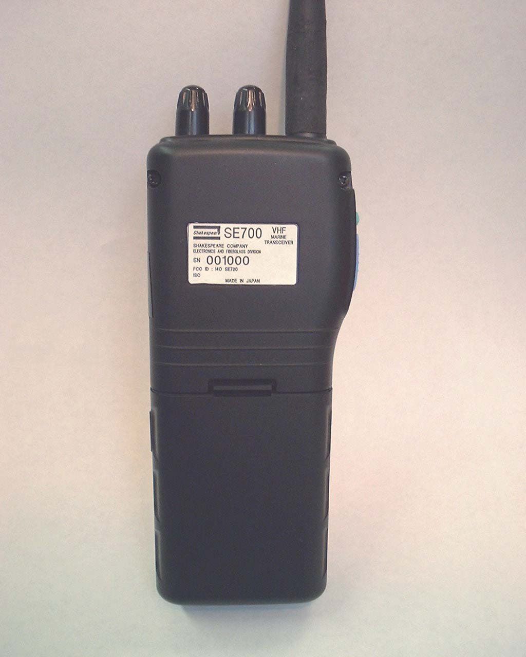
Exterior Front View Exterior Back View Exterior Side View 1 Exterior Side View 2
Internal Photos
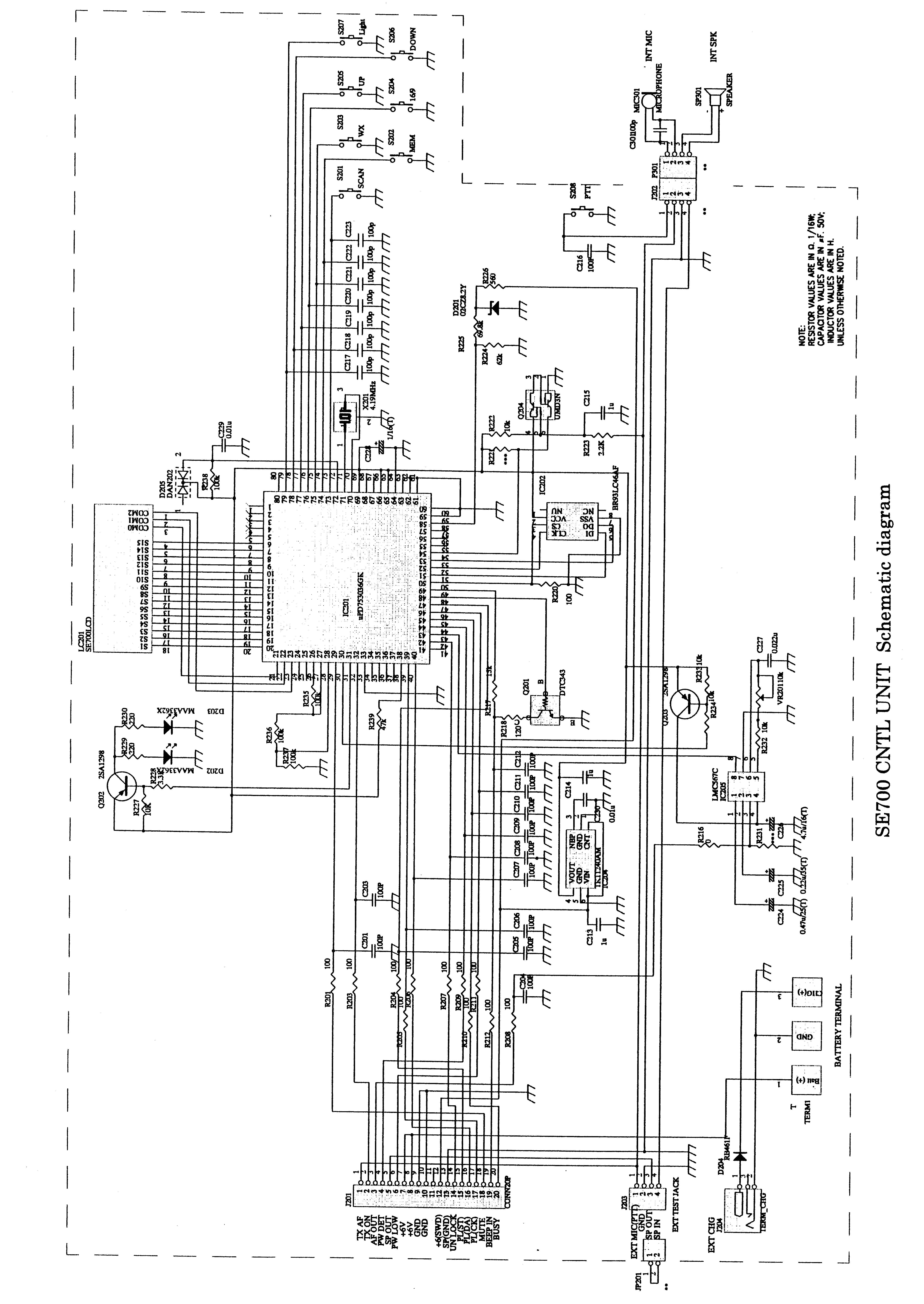
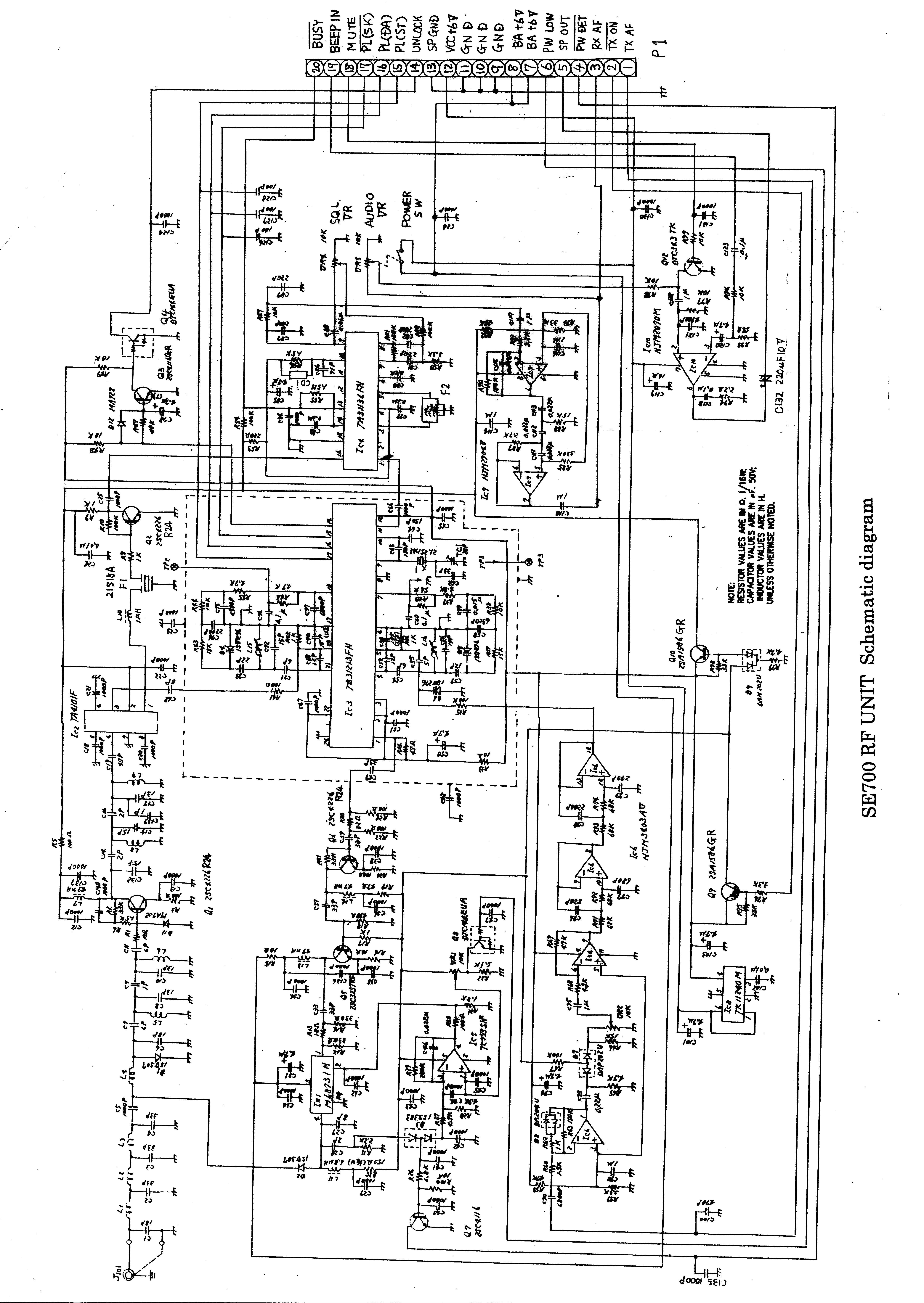
Display Board CPU Board RF Board – Track Side RF Board – Component Side Interior - Overview RF Board, Track Side – Without Shield RF Board, Component Side – Without Shield
Test Report
ENGINEERING STATEMENT For Type Certification of SHAKESPEARE COMPANY Model No: SE700 FCC ID: I40SE700 I am an Electronics Engineer, a principal in the firm of Hyak Laboratories, Inc., Springfield, Virginia. My education and experience are a matter of record with the Federal Communications Commission. Hyak Laboratories, Inc. has been authorized by Shakespeare Company to make type certification measurements on the SE700 transceiver. These tests made by me or under my supervision in our Springfield laboratory. Test data required by the FCC for type certification are included in this report. It is submitted that the above mentioned transceiver meets FCC requirements and type Certification is requested. ______________________________ Rowland S. Johnson Dated: October 7, 1999 A. INTRODUCTION 2 The following data are submitted in connection with this request for type certification of the SE700 transceiver in accordance with Part 2, Subpart J of the FCC Rules. The SE700 is a portable, 1 or 5 watt, VHF, frequency modulated transmitter/receiver combination intended for applications in the 156-163 MHz band. B. GENERAL INFORMATION REQUIRED FOR TYPE CERTIFICATION (Paragraph 2.983 of the Rules) 1. Name of applicant: Shakespeare Company 2. Identification of equipment: FCC ID: I40SE700 a. The equipment identification label is submitted as a separate exhibit. b. Photographs of the equipment are submitted as a separate exhibit. 3. Quantity production is planned. 4. Technical description: a. 16k0F3E emission Frequency range: 156-162.6 MHz. b. Operating power of transmitter is fixed at the factory at 5 watts, with provisions for reduction to one watt. d. Maximum power permitted under Part 80 of the FCC Rules is 25 watts, with capability to reduce, readily, to one watt maximum. The SE700 meets both these requirements. e. The dc voltage and dc currents at final amplifier: Collector voltage: 6.4 Vdc Collector current: 1.1 A f. Function of each active semiconductor device: See Appendix 1. g. Complete circuit diagram is submitted as a separate exhibit. h. A draft instruction book is submitted as a separate exhibit. i. The transmitter tune-up procedure is submitted as a separate exhibit. j. A description of circuits for stabilizing frequency is included in Appendix 2. B. GENERAL INFORMATION (continued) 3 k. A description of circuits and devices employed for suppression of spurious radiation and for limiting modulation is included in Appendix 3. l. Not applicable. 5. Data for 2.985 through 2.997 follow this section. 6. The equipment identification label is submitted as a separate exhibit. 7. Photographs of the equipment are submitted as separate exhibits. 8. RF Power Output (Paragraph 2.987(a) of the Rules) RF power output was measured with a Bird 4421 RF power meter and a Narda 765-20 power attenuator as a 50-ohm dummy load. (The transmitter was tuned by the factory according to the procedure of Appendix 4.) A power output of 5.2 watts was measured on Channel 16 with a supply voltage of 6.5 volts at 68 o F ambient temperature, and in the lower power position, 1.2 watts. Automatic power reduction to 1 nominal watt on Channels 13 and 67 was confirmed. A manual over-ride is provided. C. MODULATION CHARACTERISTICS 1. A curve showing frequency response of the transmitter Is shown in Figure 1. Reference level was audio signal output from a Boonton 8220 modulation meter with one kHz deviation. Audio output was measured with a Audio Precision System One TRMS voltmeter and tracking generator. 2. Modulation limiting curves are shown in Figure 2. Using a Boonton 8220 modulation meter, signal level was established with a Audio Precision System One TRMS voltmeter. The curves show compliance with paragraphs 2.987(b). 3. Figure 3 is a graph of the post-limiter low pass filter which meets the requirements of paragraph 80.211(e) in providing a roll-off of 60Logf/3 dB where f is audio frequency in kHz. Measurements were made following EIA RS-152B with an Audio Precision System One tracking generator and selective voltmeter on the Boonton 8220 C. MODULATION CHARACTERISTICS (continued) 4 modulation meter audio output. 4. Occupied Bandwidth (Paragraphs 2.989(c), and 80.211(f) of the Rules) Figures 4a and 4b are plots of the sideband envelope of the transmitter taken from the display unit of a Tek- tronix 494P spectrum analyzer. Modulation corresponded to conditions of 2.989(1) and consisted of 2500 Hz tone at an input level 16 dB greater than that necessary to produce 50% modulation at 2996 Hz, the frequency of maximum response. Measured modulation under these conditions was 4.2 kHz. The plots are within the limits imposed by Part 80 for frequency modulation. The horizontal scale (frequency is 10 kHz per division) and the vertical scale (amplitude) is a logarithmic presentation equal To 10 dB per division. FIGURE 1 5 MODULATION FREQUENCY RESPONSE MODULATION FREQUENCY RESPONSE FCC ID: I40SE700 FIGURE 1 FIGURE 2 6 AUDIO LIMITER CHARACTERISTICS AUDIO LIMITER CHARACTERISTICS FCC ID: I40SE700 FIGURE 2 FIGURE 3 7 AUDIO LOW PASS FILTER RESPONSE AUDIO LOW PASS FILTER RESPONSE FCC ID: I40SE700 FIGURE 3 FIGURE 4a 8 OCCUPIED BANDWIDTH Attenuation in dB Below Mean Output Power Required On any frequency more than 50% up to and including 100% of the authorized bandwidth, 20 kHz (10-20 kHz) 25 On any frequency more than 100%, up to and including 250% of the authorized bandwidth (20-50 kHz) 35 On any frequency removed from the assigned frequency by more than 250% of the authorized bandwidth (over 50 kHz) 43+10LogP=50 (P=5.2W) OCCUPIED BANDWIDTH FCC ID: I40SE700 FIGURE 4a FIGURE 4b OCCUPIED BANDWIDTH 9 Attenuation in dB Below Mean Output Power Required On any frequency more than 50% up to and including 100% of the authorized bandwidth, 20 kHz (10-20 kHz) 25 On any frequency more than 100%, up to and including 250% of the authorized bandwidth (20-50 kHz) 35 On any frequency removed from the assigned frequency by more than 250% of the authorized bandwid…
Text truncated - open the document above for the full version.
Contact Information
Applicant
Gary A Martek(VP-R&D, Electronics Group)
Technical Contact
Hyak Laboratories, Inc.Rowland S Johnson
[email protected](703) 451-1188
7011 Calamo St., Suite 107 · Springfield, Virginia · United States
Non-Technical Contact
Hyak Laboratories, Inc.Georgia Hall
[email protected](703) 451-1188
Test Firm
Hyak Laboratories, Inc.Rowland Johnson
703-451-1188
Technical Specifications
| # | Rule Parts | Frequency Range | Power Output | Emission | Tolerance |
|---|---|---|---|---|---|
| 2 | 8 | 156 MHz - 163 MHz | 5 W | 16k0G3E | 0.001 % |
Other Applications from Shakespeare Company, LLC
I4OSE2001
Jan 18, 1996TNF - Licensed Non-Broadcast Transmitter Held to Face
Equipment Class
TNF - Licensed Non-Broadcast Transmitter Held to FaceI4OSE6000
Dec 21, 1993TNB - Licensed Non-Broadcast Station Transmitter
Equipment Class
TNB - Licensed Non-Broadcast Station TransmitterI4OSE2000
Sep 27, 1993TNB - Licensed Non-Broadcast Station Transmitter
Equipment Class
TNB - Licensed Non-Broadcast Station TransmitterI4OSE600
Sep 27, 1993TNF - Licensed Non-Broadcast Transmitter Held to Face
Equipment Class
TNF - Licensed Non-Broadcast Transmitter Held to FaceI4OSE2500MD
Feb 24, 1993TNB - Licensed Non-Broadcast Station Transmitter
Equipment Class
TNB - Licensed Non-Broadcast Station Transmitter