I6XTX001Radio Control Transmitter
Novak Electronics Inc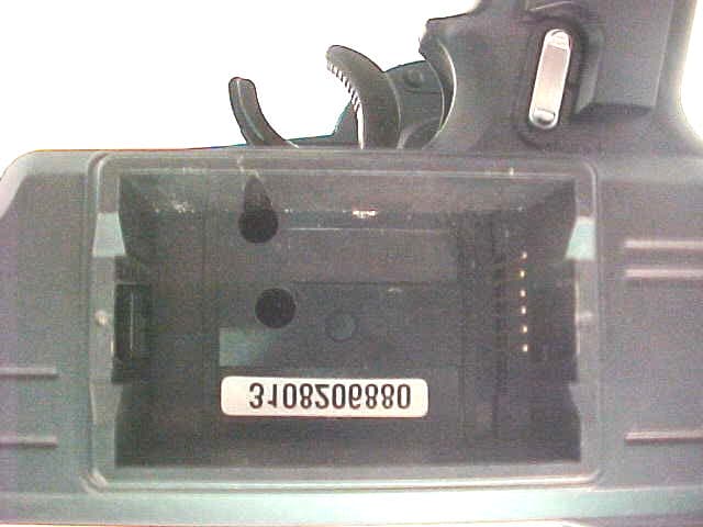
Click to zoom
Application Details
- Equipment Class
- TNB - Licensed Non-Broadcast Station Transmitter
- Date of Grant
- Jul 15, 2003
- Application Purpose
- Original Equipment
- Date of Application
- Jul 15, 2003
- Equipment Note
- Radio Control Transmitter
- Frequency Range
- 75.41000000 - 75.99000000
- Company
- Novak Electronics Inc
- Country
- United States
Documents & Files
Document Text
Text extracted from the exhibit documents filed with the FCC. Open a document above to read the original.
External Photos
Photo 1 Overall View of complete unit with Novak RF Plug-in Module Photo 2 Detail View – Hand held transmitter with RF Plug-in removed. Photo 3 Detail View - Novak RF Plug-in - Front Photo 4 Detail View - Novak RF Plug-in - Back
ID Label/Location Info
2.1033 (c) (11) Equipment Identification Plate NOTES: Label will be constructed of a material suitable for permanency on the equipment with permanent adhesive. All information on the label will be etched or stamped. Both methods will exceed the expected lifetime of the equipment. The label will be large enough to allow all information to be legible.
Internal Photos
FCC ID: I6XTX001 1 Photo 5 Detail View - PCB – Top Side FCC ID: I6XTX001 2 Photo 6 Detail View – PCB – Back Side
Operational Description
FCC ID: I6XTX001 1 2.1033 (b) (13) Brief Description of Circuit Function The device is a synthesized R.F. plug-in module for use with the Airtronics Inc. M-8 hand held transmitter. The unit is composed of a crystal controlled synthesized oscillator with a base frequency of 11.155 Mhz. This base frequency is factory tuned with trimmer capacitor C28 to meet the 0.002% tolerance. The oscillator frequency can be user changed thru two rotary switches S1 and S2 from 18.8525 to 18.9975 Mhz in 5Khz steps. The output frequency of this oscillator is applied to the first amplifier whose output is tuned to the fourth harmonic to produce the final output frequencies of 75.410 to 75.990 Mhz in 20Khz steps. This signal is sent to the next tuned amplifier to supply enough energy to drive the final class C output tuned amplifier. The output of the Class C amplifier is filtered and matched to the transmitters antenna. The synthesized oscillator is FM modulated thru a low pass filter and adjusted with potentiometer P1 to obtain the proper modulation index. The DSC input turns the power off to the module when a DSC cord is plugged into the hand held transmitter. This cord is also plugged into the receiver without danger of RF being transmitted even if the transmitters power switch is turned on. The complete module is enclosed in an orange nylon case.
Parts List/Tune Up Info
FCC ID: I6XTX001 6 2.1033 (c) (4) Type of Emissions CW 2.1033 (c) (5) Frequency Range 75.410 to 75.990 MHz in 20KHz steps 2.1033 (c) (6) Operating Power 100 mW 2.1033 (c) (7) Maximum Power Allowed in Applicable Part(s) of the Rules RULES PART MAXIMUM POWER (WATTS) Part 95.639 b 3 750mW 2.1033 (c) (8) DC Voltage Battery operated 3Vdc 2.1033 (c) (9) Tuning Procedures Rotating two 10 position rotary switches on the top of the module does the channel selection. Only positions 6, 7, 8, and 9 are used on the first switch and all 10 positions are used on the second to produce Channels 61 thru 90. (75.410 to 75.990 Mhz in 20 Khz steps). A lockout circuit in the microprocessor does not allow frequencies to be changed while power is being applied to the module
Test Report
FCC ID: I6XTX001 1 Application for Certification For an RF Transmitter for use with R/C Model Surface Craft Novak Electronics Inc. 18910 Teller Avenue Irvine, CA 92612 RF Transmitter: Part # M8FCC FCC ID: I6XTX001 REPORT # RV38044 This report was prepared in accordance with the requirements of the FCC Rules and Regulations Part 2, Subpart J, 2.1031 through 2.1057, and Part 95 and other applicable sections of the rules as indicated herein. Prepared By: Dana Grove DNB Engineering, Inc. 5969 Robinson Avenue Riverside, CA 92503 11 Nov 2002 FCC ID: I6XTX001 2 TABLE OF CONTENTS Section Title Sheet # 1.0 ADMINISTRATIVE DATA 3 1.1 Certifications and Qualifications 3 1.2 Measurements and Repeatability Information 3 Note: Paragraph numbers in this report follow the application section numbers found in the FEDERAL COMMUNICATIONS COMMISSION Rules and Regulations, Part 2, Subpart J for Certification of electronic equipment. 2.1033 (C) (1) Application for Certification 4 2.1033 (C) (2) FCC Identifier 4 2.1033 (C) (3) Installation and Operating Instructions 5 2.1033 (C) (4) Type of Emissions 6 2.1033 (C) (5) Frequency Range 6 2.1033 (C) (6) Operating Power 6 2.1033 (C) (7) Maximum Power Allowed in Applicable part(s) of the Rules 6 2.1033 (C) (8) DC Voltage 6 2.1033 (C) (9) Tune Up Procedure 6 2.1033 (C) (10) Schematic Diagrams and Circuit Descriptions 7-14 2.1033 (C) (11) Equipment Identification Plate 15 2.1033 (C) (12) Equipment Photographs 15-21 2.1033 (C) (13) Brief Description of Circuit Function 22 2.1033 (C) (14) Report of Measurements 22 2.1046 Measurement of RF Power Output 23 2.1047 Modulation Characteristics 23 2.1049 Measurement of Occupied Bandwidth 24-27 2.1051 Spurious Emissions at Antenna Terminals 28-29 2.1053 Measurement of Field Strength of Spurious Radiation 30-32 2.1055 Measurement of Frequency Stability 33 2.1057 Frequency Spectrum to be Investigated 34 15.109 Radiated Emissions – Class B 35-36 Test Equipment Log 37-39 FCC ID: I6XTX001 3 1.0 ADMINISTRATIVE DATA 1.1 Certifications and Qualifications I certify that DNB Engineering, Inc conducted the tests performed in order to obtain the technical data presented in this application. Also, based on the results of the enclosed data, I have concluded that the equipment tested meets or exceeds the requirements of the Rules and Regulations governing this application. 1.2 Measurement Repeatability Information The test data presented in this report has been acquired using the guidelines set forth in FCC Part 2.1031 through 2.1057, Part 95. The test results presented in this document are valid only for the equipment identified herein under the test conditions described. Repeatability of these test results will only be achieved with identical measurement conditions. These conditions include: The same test distance, EUT Height, Measurement Site Characteristics, and the same EUT System Components. The system must have the same Interconnecting Cables arranged in identical placement to that in the test set-up, with the system and/or EUT functioning in the identical mode of operation (i.e. software and so on) as on the date of the test. Any deviation from the test conditions and the environment on the date of the test may result in measurement repeatability difficulties. All changes made to the EUT during the course of testing as identified in this test report must be incorporated into the EUT or identical models to ensure compliance with the FCC regulations. C. L. Payne III (Para. 1.1) Manager, Riverside Facility. DNB Engineering, Inc. Tel. (909) 637-2630 FAX (909) 637-2704 FCC ID: I6XTX001 4 2.1033 (c) (1) Application for Certification Name of Applicant: Novak Electronics Inc. 18910 Teller Avenue Irvine, CA 92612 Applicant is: X Manufacturer Vendor Licensee Prospective Licensee Other Name of Manufacturer Novak Electronics Inc. Description: RF Transmitter Part Number: M8FCC Anticipated Production Quantity: Multiple Units 2.1033 (c) (2) FCC Identifier FCC ID: I6XTX001 FCC ID: I6XTX001 5 2.1033 (c) (3) Installation and Operating Instructions Complete information to the user is located on the product carton as depicted below. FCC ID: I6XTX001 6 2.1033 (c) (4) Type of Emissions CW 2.1033 (c) (5) Frequency Range 75.410 to 75.990 MHz in 20KHz steps 2.1033 (c) (6) Operating Power 100 mW 2.1033 (c) (7) Maximum Power Allowed in Applicable Part(s) of the Rules RULES PART MAXIMUM POWER (WATTS) Part 95.639 b 3 750mW 2.1033 (c) (8) DC Voltage Battery operated 3Vdc 2.1033 (c) (9) Tuning Procedures Rotating two 10 position rotary switches on the top of the module does the channel selection. Only positions 6, 7, 8, and 9 are used on the first switch and all 10 positions are used on the second to produce Channels 61 thru 90. (75.410 to 75.990 Mhz in 20 Khz steps). A lockout circuit in the microprocessor does not allow frequencies to be changed while power is being applied to the module FCC ID: I6XTX001 7 2.1033 (c) (10) Schematic Diagram and Circuit Description FCC ID: I6XTX001 8 FCC ID: I6XTX001 9 FCC ID: I6XTX001 10 FCC ID: I6XTX001 11 FCC ID: I6XTX001 12 FCC ID: I6XTX001 13 FCC ID: I6XTX001 14 FCC ID: I6XTX001 15 2.1033 (c) (11) Equipment Identification Plate NOTES: Label will be constructed of a material suitable for permanency on the equipment with permanent adhesive. All information on the label will be etched or stamped. Both methods will exceed the expected lifetime of the equipment. The label will be large enough to allow all information to be legible. 2.1033 (c) (12) Equipment Photographs Photo 1 Overall View of complete unit with Novak RF Transmitter Module Photo 2 Detail View – Hand held transmitter with RF Transmitter removed Photo 3 Detail View - Novak RF Transmitter - Front Photo 4 Detail View - Novak RF Transmitter - Back Photo 5 Detail View - PCB – Top Side Photo 6 Detail View – PCB – Back Side FCC ID: I6XTX001 16 Photo 1 Overall View of complete unit with Novak RF Transmitter Module FCC ID: I6XTX001 17 Photo 2 Detail View – Hand held transmitte…
Text truncated - open the document above for the full version.
Test Report
Effective Radiated Power,Pass [X] Fail [ ] N/A [ ] The EUT was measured on an open area test site (OATS) in accordance to the provisions in Annex A of the standard. A measuring distance of at least 3 m shall be used for measurements at frequencies up to 1 GHz. For frequencies above 1 GHz, any suitable measuring distance may be used. The equipment size (excluding the antenna) shall be less than 20 % of the measuring distance. The height of the equipment or of the substitution antenna shall be 1,5 m; the height of the test antenna (transmit or receive) shall vary between 1 m and 4 m. Sufficient precautions shall be taken to ensure that reflections from extraneous objects adjacent to the site do not degrade the measurement results, in particular: - no extraneous conducting objects having any dimension in excess of a quarter wavelength of the highest frequency tested shall be in the immediate vicinity of the site; - all cables shall be as short as possible; as much of the cables as possible shall be on the ground plane or preferably below; and the low impedance cables shall be screened. The EUT shall be placed upon a non-conductive table 1.5 meters above the ground plane and shall be placed in the “worst case” transmitting mode. The EUT shall be rotated 360 degrees to find the azimuth maxima. The receive antenna shall then be raised and lowered between 1 to 4 meters to find the maximum signal emanating from the EUT. Once the maximum has been identified and recorded the EUT is replaced with a tuned dipole at the appropriate frequency and a signal generator is input into the dipole. The level is raised until the same signal strength is achieved. This signal strength is then recorded on the data sheets. Note: To obtain the effective power the spectrum analyzer was placed in average mode and the time was decreased in order to get a true representation of the effective radiated power in the spectrum. 5969 Robinson Avenue Riverside, CA 92503 (909) 637-2630 FAX (909) 637-2704 XMTR Effective Radiated Power (ERP) DNB Job Number:38044Date:30 Sep 2002 Conformance Standard FCC Title 47 Part 95 Customer:Novak Electronics Model Number:M8Serial Number: Description:R/C Transmitter Clause 95.210 Environmental Conditions Ambient TemperatureRelative HumidityBarometric Pressure 31 °C37 %101.2 kPa Rated Radiated Power in W750mWRated Radiated Power in dBm28.75 dBm Polarization of the measurement for the largest power level (Horizontal or Vertical)Vertical TESTS Measured Power (W/dBm) and Variation (W/dB) Channel 1Channel 2Channel 3 WdBmWdBmWdBm Measured Radiated Power0.081319.10N/aN/aN/aN/a VariationN/o *N/o *N/aN/aN/aN/a Measurement Uncertainty +/- 0.5dB Limit per FCC Part 95.210750mW (27.5dBm) NotesN/o * = No Variation observed during test Test performed under normal operating conditions EUT performed within the requirements of the applicable standard [X] Yes [ ] No
Contact Information
Applicant
Robert Novak
Test Firm
DNB Engineering, Inc.Mike Neis
Technical Specifications
| # | Rule Parts | Frequency Range | Power Output | Emission | Tolerance |
|---|---|---|---|---|---|
| 1 | 95C | 75.41 MHz - 75.99 MHz | 81.30 mW | 8K00F1D | 0.0050000000 % |
Other Applications from Novak Electronics Inc
I6XNER2375
Oct 02, 1996CXX - Communications Rcvr for use w/ licensed Tx and CBs
Equipment Class
CXX - Communications Rcvr for use w/ licensed Tx and CBsI6XNER-3AM-1
Aug 10, 1994R/C Toy Receiver
Equipment Class
CYY - Communications Receiver used w/Pt 15 TransmitterI6XNER-3AM-2
Aug 09, 1994CYY - Communications Receiver used w/Pt 15 Transmitter
Equipment Class
CYY - Communications Receiver used w/Pt 15 TransmitterI6XNER-3FM
Jun 05, 1991CXX - Communications Rcvr for use w/ licensed Tx and CBs
Equipment Class
CXX - Communications Rcvr for use w/ licensed Tx and CBs