I84AS1795COLOR MONITOR
A Plus Info Corp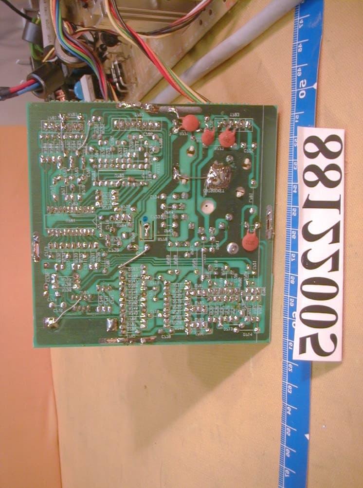
Click to zoom
Application Details
- Equipment Class
- JBP - Part 15 Class B Computing Device Peripheral
- Date of Grant
- Apr 23, 2000
- Application Purpose
- Original Equipment
- Date of Application
- Jan 11, 2000
- Equipment Note
- COLOR MONITOR
- Company
- A Plus Info Corp
- Country
- Taiwan
Documents & Files
Document Text
Text extracted from the exhibit documents filed with the FCC. Open a document above to read the original.
Users Manual
Federal Communications Commission (FCC Statement) This device has been tested and found to comply with the limits for a Class B digital device, pursuant to Part 15 of the FCC Rules. These limits are designed to provide reasonable protection against harmful interference in a residential installation. This equipment generates, uses, and can radiate radio frequency energy. If not installed in accordance with the instructions in this manual, harmful interference to radio communication may occur. However, there is no guarantee that interference will not occur in a particular installation. If this equipment does cause interference to radio and television reception, which can be determined by turning the equipment off and on, the user is encouraged to correct the interference by one or more of the following measures: l Re-orient or relocate the receiving antenna. l Increase the space between the equipment and receiver. l Connect the equipment into an outlet on a circuit different from the one that the receiver is connected. l Consult the dealer or an experienced radio/TV technician for help. l Use only RF shielded cable to connect this monitor to a computer device. Installation and Operation 1. Shut down and power off computer. Connect the 15-pin video signal cable to the appropriate socket on the PC, and lock attached screws to ensure proper connection between monitor and PC system. Connect power cord to monitor. Connect the other end of power cord to appropriate power source – for plugable equipment the Socket-Outlet shall be installed near the Monitor and shall be easily accessible. 2. Power up computer. The monitor simultaneously auto detects the frequency of the input video signal and display the picture. 3. Use the main control knob to adjust the display: l Press the control knob once to bring up the On-Screen-Display menu in “selecting mode”. l In selecting mode, rotate the control knob clockwise or counter- clockwise to select feature for adjustment. The selected icon is displayed in red and all others in white. Press the control knob once to enter “adjusting mode”, the “%” mark starts blinking. l In adjusting mode, rotate the control knob clockwise or counter- clockwise to adjust the selected feature. Press the control knob once again to return to selecting mode, the “%” mark stops blinking. l If the control knob is not operated for more than 10 seconds, the display will save the adjusted settings and turn the On-Screen- Display menu off. 4. If horizontal or vertical frequency is out of the operating range as specified in the specification, the display enters power saving mode and the power indicator blinks. If both are out of range, the display turns off and power LED is extinguished. 5. Press the power saving button (beside the main control knob) to force the display into power saving mode and power indicator off. Press the power saving button again to resume operation. OSD ICON Descriptions ICON Display Feature (page 1) ICON Display Feature (page 2) Save seting and escapeDegauss function Vertical SizeVertical morie Vertical PositionHorizontal morie Horizontal SizeVertical dynamic focus Horizontal PhaseHorizontal dynamic focus Trapezoid9300K color temerpture Pincushion6500K color temperture ParallelogramRed video gain control Pin-BalanceGreen video gain control Vertical S correctionBlue video gain control Vertical C correctionRecall factory function Horizontal linearityRed Bias adjustment Cornor correctionGreen Bias adjustment Recall factory functionBlue Bias adjustment Tilt controlSelect input level 0.7/1.0V Next pageNext page BrightnessVertical OSD position ContrastHorizontal OSD position Specifications CRTSize & Dot Pitch17” - 0.26 / 0.28mm Face TreatmentNon-glare Deflection Angle90° DisplayFactory setting300x225mm (11.8x8.86”) SizeOver Scan325x244mm (12.8x9.61”) DisplayHorizontal Freq.30~95Khz30~70Khz FormatVertical Freq.50~160Hz50~125Hz Max. Resolution (N.I.) 1600x12001280x1024 Bandwidth150Mhz Memories26 Sets20 Sets InputConnectivityEnhanced VESA standards, MAC II SignalVideo SignalRGB Analog 0.7 or 1.0 Vp-p Connector15 Pin D-shell Input Voltage100~240Vac, 50/60Hz Consumption110W85W Sleep Mode10W Deep Sleep Mode 1W Power PFCOption MechanicalDimension(HxWxD)420x410x440mm (16.5x16.1x17.3”) SpecsPacking(HxWxD)537x527x575mm (21.1x20.7x22.6”) AdjustmentTilt and Swivel External Control On Screen DisplayContrast, Brightness, V-Size, V-Position, H- Size, H-Phase, Trapezoid, Pincushion, Parallelogram, Pin-Balance, H-Linearity, S/C/Cornor, Tilt, Degauss, H/V Morie, Red/Green/Blue Intensity, Input Level, Red/Green/Blue Bias Intensity, 9300/6500, Horizontal/Vertical Dynamic Focus Plug & PlayWindows 98 compliant DDC1 / 2B SpeakerExternalOptional Pin Assignment Pin 1:RPin 6:GndPin11:Gnd Pin 2:GPin 7:Gndn 12:SDA Pin 3:BPin 8:GndPin 13:H-sync Pin 4:GndPin 9:+5VPin 14:V-sync Pin 10:GndPin 15:SCL Wichtige Sicherheitshinweise 1. Bitte Lesen Sie sich diese Hinweise sorgfältig durch. 2. Heben Sie diese Anleitung für den späteren Gebrauch auf. 3. Vor jedem Reinigen ist das Gerät vom Stromnetz zu trennen. Verwenden Sie keine Flüssigoder Aerosolreiniger. Am besten dient ein angefeuchtetes Tuch zur Reinigung. 4. Um eine Beschädigung des Gerätes zu vermeiden sollten Sie nur Zubehörteile verwenden, die vom Hersteller zugelassen sind. 5. Das Gerät ist vor Feuchtigkeit zu schützen. 6. Bei der Aufstellung des Gerätes ist auf sicheren Stand zzu achten, Ein Kippen oder Fallen könnte Verletzungen hervorrufen. Verwenden Sie nur sichere Standorte und beachten Sie die Aufstellhinweise des Herstellers. 7. Die Belüftungsöffnungen dienen zur Luftzirkulation die das Gerät vor Überhitzung schützt. Sorgen Sie dafür,daß diese Öffnungen nicht abgedeckt werden. 8. Beachten Sie beim Anschluß an das Stromnetz die Anschlußwerte. 9. Die Netzanschlußsteckdose muß aus Gründen der elektrischen Sicherheit einen Schutleiterkontakt haben. 10. Verlegen Sie die Netzanschlußleitung so,daß niemand darüber fallen kann. Es sollte auch nic…
Text truncated - open the document above for the full version.
Cover Letter(s)
Federal Communications CommissionDate: Jan. 6, 2000 Authorization and Evaluation Division 7435 Oakland Mills Rd. Columbia, MD. 21046 Attention: Authorization and Evaluation Division Subject: Application for Certification on COLOR MONITOR (EUT) with FCC ID: I84AS1795 Dear Sir: We would like to apply for FCC certification of the EUT. Enclosed please find all required documents of the EUT listed below: 1. Exhibit 1 : The Authorization Letter signed by the applicant 2. Exhibit 2 : The FCC Label of EUT 3. Exhibit 3 : The modification List Letter signed by the applicant 4. Exhibit 4 : The RFI/EMI Test Report issued by ADT Corp. 5. Exhibit 5 : The photographs of EUT 6. Exhibit 6 : The Block Diagram & Schematic Diagram of EUT 7. Exhibit 7 : The User’s Manual of EUT Please review the information we submitted and issue us a grant for the EUT. If you have any questions or comments, please do not hesitate to contact Mr. Mike Su of ADT Lab. at fax no.: 886-2-2602-2943 or e-mail: [email protected] Sincerely yours, Cc. Mr. Harris W. Lai / Advance Data Technology Corporation
ID Label/Location Info
(Fig. 1) FCC ID: I84AS1795 The label will be permanently affixed at a conspicuous location on the device. LABEL
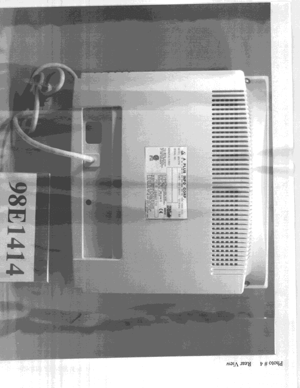
Internal Photos
(Photo 1) FCC ID: I84AS1795 (Photo 2) FCC ID: I84AS1795 1 (Photo 3) FCC ID: I84AS1795 (Photo 4) FCC ID: I84AS1795 2 (Photo 5) FCC ID: I84AS1795 2 (Photo 6) FCC ID: I84AS1795 1 3 4 5 (Photo 7) FCC ID: I84AS1795 6 7 8 (Photo 8) FCC ID: I84AS1795 (Photo 9) FCC ID: I84AS1795 (Photo 10) FCC ID: I84AS1795 9 9 9 (Photo 11) FCC ID: I84AS1795 (Photo 12) FCC ID: I84AS1795 10 10 10 10 (Photo 13) FCC ID: I84AS1795 (Photo 14) FCC ID: I84AS1795 (Photo 15) FCC ID: I84AS1795
Test Report
ADVANCE DATA TECHNOLOGY CORPORATION REPORT NO.: F88122005 Page 1 FCC ID: I84AS1795 EMC TEST REPORT REPORT NO.: F88122005 MODEL NO.: AS1795 DATE OF TEST: Dec. 23, 1999 PREPARED FOR : A PLUS INFO CORPORATION ADDRESS : 5FL, NO. 2, LANE 235, BAO CHIAO RD., HSIN TIEN, TAIPEI HSIEN, TAIWAN, R.O.C. PREPARED BY:ADVANCE DATA TECHNOLOGY CORPORATION 11F, NO.1, SEC.4, NAN-KING EAST RD., TAIPEI, TAIWAN, R.O.C. This test report consists of 19 pages in total. It may be duplicated completely for legal use with the allowance of the applicant. It shall not be reproduced except in full, without the written approval of our laboratory. It should not be used by the client to claim product endorsement by NVLAP or any agency of the U.S. government. The test result in the report only applies to the tested sample. Accredited Laboratory ADVANCE DATA TECHNOLOGY CORPORATION REPORT NO.: F88122005 Page 2 FCC ID: I84AS1795 TABLE OF CONTENTS 1.CERTIFICATION.............................................................................................................3 2.GENERAL INFORMATION............................................................................................4 2.1GENERAL DESCRIPTION OF EUT....................................................................4 2.2DESCRIPTION OF SUPPORT UNITS.................................................................5 2.3TEST METHODOLOGY AND CONFIGURATION............................................5 3.TEST INSTRUMENTS....................................................................................................6 3.1TEST INSTRUMENTS (EMISSION)...................................................................6 3.2LIMITS OF CONDUCTED AND RADIATED EMISSION..................................7 4.TEST RESULTS (EMISSION)......................................................................................8 4.1RADIO DISTURBANCE......................................................................................8 4.2EUT OPERATION CONDITION.........................................................................8 4.3TEST DATA OF CONDUCTED EMISSION (A).................................................9 4.4TEST DATA OF CONDUCTED EMISSION (B)...............................................11 4.5TEST DATA OF RADIATED EMISSION (A)...................................................13 4.6TEST DATA OF RADIATED EMISSION (B)...................................................15 5.PHOTOGRAPHS OF THE TEST CONFIGURATION WITH MINIMUM MARGIN....17 6.APPENDIX - INFORMATION OF THE TESTING LABORATORY............................19 ADVANCE DATA TECHNOLOGY CORPORATION REPORT NO.: F88122005 Page 3 FCC ID: I84AS1795 1. CERTIFICATION Issue Date: Dec. 27, 1999 Product:COLOR MONITOR Trade Name:APLUS Model No.:AS1795 Applicant:A PLUS INFO CORPORATION Standard:FCC Part 15, Subpart B, Class B CISPR 22: 1993+A1: 1995+A2: 1996, Class B ANSI C63.4-1992 We hereby certify that one sample of the designation has been tested in our facility on Dec. 23, 1999. The test record, data evaluation and Equipment Under Test (EUT) configurations represent herein are true and accurate representation of the measurements of the sample's EMC characteristics under the conditions herein specified. The test results show that the EUT as described in this report is in compliance with the Class B limits of conducted and radiated emission of applicable standards. ADVANCE DATA TECHNOLOGY CORPORATION Accredited Laboratory ADVANCE DATA TECHNOLOGY CORPORATION REPORT NO.: F88122005 Page 4 FCC ID: I84AS1795 2. GENERAL INFORMATION 2.1 GENERAL DESCRIPTION OF EUT Product:COLOR MONITOR Model No.:AS1795 Power Supply Type:Switching Power Cord:Nonshielded (1.8m, 3-pin) Data Cable:Shielded (1.2m) Note: The EUT is a 17” color monitor with resolution up to 1600x1200. The EUT was pre-tested under the following resolution & horizontal synchronization speed modes: ♦ 1600 x 1200 mode (93 kHz), ♦ 1280 x 1024 mode (91 kHz), ♦ 1024 x 768 mode (69 kHz), ♦ 640 x 480 mode (31.5 kHz) For the final test, the worst emission levels were found under these two modes: MODE 1 - 1600 x 1200 (93 kHz) MODE 2 - 1024 x 768 (69 kHz) Both modes are tested separately and recorded in this report. There is a ferrite core on the video cable outside the monitor. For more detailed features description, please refer to manufacturer's specification or User's Manual. ADVANCE DATA TECHNOLOGY CORPORATION REPORT NO.: F88122005 Page 5 FCC ID: I84AS1795 2.2 DESCRIPTION OF SUPPORT UNITS The EUT has been tested as an independent unit together with other necessary accessories or support units. The following support units or accessories are used to form representative test configuration during the tests. No.ProductBrandModel No.FCC IDI/O Cable 1. PERSONAL COMPUTER NTIPII-150MT FCC DoC Approved Nonshielded Power (1.8m) 2. KEYBOARDFORWARDFDA-104GAF4ZDA-104GShielded Signal (1.4m) 3. MOUSEDEXINA2P800ANIYA2P800AShielded Signal (1.5m) 4. PRINTERHP2225C+DSI6XU2225 Shielded Signal (1.2m) Nonshielded Power (1.8m) 5. MODEMACEEX1414IFAXDM1414 Shielded Signal (1.2m) Nonshielded Power (1.8m) 6. VGA CARDGAINWARD S3d VIRGE GX2 ICUVGA- GW710 NA 2.3 TEST METHODOLOGY AND CONFIGURATION Both conducted and radiated testing were performed according to the procedures in ANSI C63.4: 1992. Radiated testing was performed at an antenna to EUT distance of 3/ 10 m on an open area test site. Please refer to the photos of test configuration in Item 5. ADVANCE DATA TECHNOLOGY CORPORATION REPORT NO.: F88122005 Page 6 FCC ID: I84AS1795 3. TEST INSTRUMENTS 3.1 TEST INSTRUMENTS (EMISSION) CONDUCTED EMISSION MEASUREMENT Description & ManufacturerModel No.Serial No.Calibrated Until ROHDE & SCHWARZ Test Receiver ESHS30828109/007July 13, 2000 ROHDE & SCHWARZ Artificial Mains Network ESH2-Z5892107/003July 13, 2000 EMCO L.I.S.N.3825/29504-2359July 13, 2000 Shielded RoomSite 3ADT-C03NA Note: 1. The measurement uncertainty is less than +/- 2.6dB, which is calculated as per NAMAS document NIS81. 2. The calibration interval of the abo…
Text truncated - open the document above for the full version.
Contact Information
Applicant
Kao-wan Lee(Engineer)
886 2 2267-7168Fax: 886 2 2267-3460
Technical Contact
Advance Data Technology Corp.Mike Su
[email protected]886-2-26032180
No. 47, 14 Ling, Chia Pau Tsuen · Taipei Hsien · Taiwan
Non-Technical Contact
Advance Data Technology Corp.Mike Su
[email protected]886-2-26032180
Test Firm
Bureau Veritas CPS (H.K.) Ltd., Taoyuan BranchRichard Chen
Technical Specifications
| # | Rule Parts | Frequency Range | Power Output |
|---|---|---|---|
| 1 | 15B | - | - |
Other Applications from A Plus Info Corp
I84AS1770
Jan 05, 1999JBP - Part 15 Class B Computing Device Peripheral
Equipment Class
JBP - Part 15 Class B Computing Device PeripheralI84AS1570
Sep 29, 1998JBP - Part 15 Class B Computing Device Peripheral
Equipment Class
JBP - Part 15 Class B Computing Device PeripheralI84AS1454
Sep 29, 1998JBP - Part 15 Class B Computing Device Peripheral
Equipment Class
JBP - Part 15 Class B Computing Device PeripheralI84CM1454
Jul 20, 1997JBP - Part 15 Class B Computing Device Peripheral
Equipment Class
JBP - Part 15 Class B Computing Device PeripheralI84CM1570
Jul 08, 1997JBP - Part 15 Class B Computing Device Peripheral
Equipment Class
JBP - Part 15 Class B Computing Device Peripheral