IFKTMPTire Monitor Sensor
NEXION S.p.A.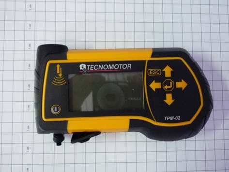
Click to zoom
Application Details
- Equipment Class
- DCD - Part 15 Low Power Transmitter Below 1705 kHz
- Date of Grant
- Aug 07, 2012
- Application Purpose
- Original Equipment
- Date of Application
- Aug 07, 2012
- Equipment Note
- Tire Monitor Sensor
- Frequency Range
- 0.12500000 - 0.12500000
- Company
- NEXION S.p.A.
- Country
- Italy
Documents & Files
Document Text
Text extracted from the exhibit documents filed with the FCC. Open a document above to read the original.
Users Manual
How to use the TPM-02 CONTROL, DIAGNOSIS AND CODING TOOL FOR TPMS SYSTEMS Operating Instructions (ENGLISH) Produced by TECNOMOTOR S.p.A All rights reserved. This publication may not be reproduced, in full or in part, without the express written consent of TECNOMOTOR S.p.A. TECNOMOTOR S.p.A reserves the right to revise or make changes to this publication without prior notice. Copyright information All other product and firm names within this manual may be trademarks of other entities. 3 TABLE OF CONTENTS 1.Symbols used in the manual .............................................................................................5 2.Safety rules........................................................................................................................5 3.Upon receipt......................................................................................................................7 4.Package contents ...............................................................................................................7 4.1OBD Option ..................................................................................................................7 5.Maintenance and care .......................................................................................................7 6.How to power on/off the equipment .................................................................................8 7.Recharging the equipment (par.7) ....................................................................................8 8.Settings..............................................................................................................................8 9.What is a TPMS system? ..................................................................................................9 10.TPMS indicator lights ...................................................................................................9 11.Type of sensors............................................................................................................10 12.How to position the equipment ...................................................................................11 13.Functions .....................................................................................................................12 13.1. Keypad ....................................................................................................................... 12 13.2. Sensor Test ................................................................................................................. 12 13.3. Tightening Torques .................................................................................................... 14 13.4. Part Number ............................................................................................................... 15 13.5. Tire Rotation and Sensor Replacement...................................................................... 16 13.6. Car Test ...................................................................................................................... 17 14.Test database ...............................................................................................................18 14.1. Vehicle Data Log: ...................................................................................................... 19 14.2. Sensors Data Log: ...................................................................................................... 19 14.3. Upload to PC:............................................................................................................. 19 15.Vehicle remote control test .........................................................................................19 16.Sensor installation/removal procedure ........................................................................20 16.1. Maintenance equipment required for TPMS-equipped tires...................................... 20 16.2. Sensor replacement .................................................................................................... 21 16.3. Servicing the sensor with the tire installed. ............................................................... 22 17.Tire removal ................................................................................................................23 17.1. Breaking the bead....................................................................................................... 23 17.2. Breaking the upper bead ............................................................................................ 24 17.3. Breaking the lower bead ............................................................................................ 24 17.4. Tire installation .......................................................................................................... 25 17.5. Seating the lower bead ............................................................................................... 25 17.6. Seating the external bead ........................................................................................... 25 18.Hardware and software requirements for update/data upload PC...............................26 19. UP DATING THE TOOL (PRENDERE PARTE AGGIO TPM1)................................27 4 Foreword Dear Customer, Thanks for choosing our product. This product has been designed to give you years of satisfactory service. To ensure this, please read this User Manual thoroughly before using the product and keep the manual in a safe place for future reference. Our exhaustive range of products sets a new standard in TPMS (Tire Pressure Monitoring System) diagnostics while offering an aesthetically pleasing design. All of our products are designed and manufactured to the highest quality standards. TPM-02 will prove an indispensable tool for: •Checking sensor operation before servicing the tires (when vehicle is brought in for service or repair). •Establishing proper operation of the TPMS system wh…
Text truncated - open the document above for the full version.
Block Diagram
Quality System Edit. : 1 Date : 18/06/2012 Quality Documents Note and reference: UNI EN ISO 9001 (2008) Block Diagram Questo documento è di proprietà del TECNOMOTOR S.p.A. e non può essere usato, riprodotto o reso noto a terzi, senza autorizzazione scritta della Direzione Gestione Qualità TECNOMOTOR S.p.A. Pagina 1 di 1 BLOCKS : 1. Supervisor recharge circuit 2. Li‐ion battery 3. Switching power supply for energy saving 4. USB interface 5. Cpu NXP ARM7 6. Receiver RF 315MHz / RF433.92MHz / RF 868MHz / 915 MHZ 7. Diagnostic cable 8. Power circuit to generate the excitation signal at 125kHz 9. Keyboard with 7 keys 10. Buzzer for various signalling 11. 128 x 64 pixel LCD display 12. Excitation coil 13. Main Power suppy Quality System Edit. : 1 Date : 18/06/2012 Quality Documents Note and reference: UNI EN ISO 9001 (2008) Block Diagram Questo documento è di proprietà del TECNOMOTOR S.p.A. e non può essere usato, riprodotto o reso noto a terzi, senza autorizzazione scritta della Direzione Gestione Qualità TECNOMOTOR S.p.A. Pagina 2 di 2 Block Diagram Charger Battery Supervisor LI-ION Battery Power supply CPU Diagnostic cable Antenna RF Keyboard Display USB interface Switching Power supply LF DRIVER Excitation coil 3 5 2 1 4 7 6 8 9 10 Buzzer 11 12 13 Quality System Edit. : 1 Date : 18/06/2012 Quality Documents Note and reference: UNI EN ISO 9001 (2008) Block Diagram Questo documento è di proprietà del TECNOMOTOR S.p.A. e non può essere usato, riprodotto o reso noto a terzi, senza autorizzazione scritta della Direzione Gestione Qualità TECNOMOTOR S.p.A. Pagina 3 di 3 1. Supervisor recharge circuit Battery management Charge Level indicator Automatic power off 2. Li‐ion battery High capacity 11.1 V 800 mAh 3. Switching power supply for energy saving Switching supply circuit at low power for best energy saving 4. USB interface For update/data upload to PC 5. Cpu NXP ARM7 Cpu to control the display/LEDs, the keyboard, the buzzer, the serial connections, rf and Lf device. 6. Receiver RF 315MHz / RF433.92MHz / RF 868MHz / 915 MHZ Ultra low‐power wireless applications operating in the 315/433/868/915 MHz ISM/SRD bands Frequency bands: 300‐348 MHz, 387‐464 MHz and 779‐928 MHz High sensitivity : ‐116 dBm at 0.6 kBaud, 433 MHz, 1% packet error rate ‐112 dBm at 1.2 kBaud, 868 MHz, 1% packet error rate Excellent receiver selectivity and blocking performance Programmable data rate from 0.6 to 600kbps Flexible support for packet oriented systems; On‐chip support for sync word detection, address check, flexible packet length, and automatic CRC handling Efficient SPI interface; All registers can beprogrammed with one “burst” transfer Digital RSSI output Programmable channel filter bandwidth, Programmable Carrier Sense (CS) indicator Programmable Preamble Quality Indicator (PQI) for improved protection against false sync word detection in random noise Support for automatic Clear Channel Assessment (CCA) before transmitting (for listen‐before‐talk systems) Support for per‐ package Link Quality Indication (LQI) , Optional automatic whitening and dewhitening of data 7. Diagnostic cable to reprogram sensors, read and delete control unit errors, enable and disable TPMS, detect pressure, battery status and temperature, set winter and summer tires. 8. Power circuit to generate the excitation signal at 125kHz Integrated power excitation coil used to create the magnetic field continuous or modulated wave 9. Keyboard with 7 keys Easy key command 10. Buzzer for various signalling 11. 128 x 64 pixel LCD display 12. Excitation coil generate a 125kHz electromagnetic field 13. Power supply Universal voltage power supply
Cover Letter(s)
APPARECCHIATURE PER DIAGNOSI MOTORI TECNOMOTOR S.p.A. - Società soggetta a direzione e coordinamento di Nexion S.p.A. Via Moruzzi 3/A, 43100 PARMA - Tel. +39 0521398211 (r.a.) - Telefax +39 0521607586 CF, Partita IVA, R.I. Parma 00697030344 – Capitale Sociale €. 900.000 i.v. – R.E.A. PR 158235 – N. Meccanogr. PR 000648 Modulo del Sistema Qualità Rev. 1 Federal Communications Commission 7435 Oakland Mills Road Columbia, MD 21046 Gentlemen: This letter is to comply with Sections 0.457 and 0.459 pertaining to confidential material. TECNOMOTOR S.p.A. would like the following documents regarding this submission for FCC ID: IFKTPM to be kept confidential. 1. Block diagram 2 . Operation Description/Theory of Operation 3. Parts List & Placement/BOM 4. Schematics The above material contains trade secrets or technical data, which would customarily be guarded from competitors. We do not want these documents to be accessible to the general public. Sincerely, Ing. Caso Antonio TECNOMOTOR SpA Parma, 08 August 2012
External Photos
G.S.D. S.r.l. Via Marmiceto, 8 - 56121 Ospedaletto (Pisa) Italy This document may be only fully reproduced. Every partial reproduction is only allowed after written approval released by G.S.D. S.r.l. Report n. 12951 -FCC Rev. 00, page 1 / 1 EUT identification – external view
Internal Photos
G.S.D. S.r.l. Via Marmiceto, 8 - 56121 Ospedaletto (Pisa) Italy This document may be only fully reproduced. Every partial reproduction is only allowed after written approval released by G.S.D. S.r.l. Report n. 12951 -FCC Rev. 00, page 1 / 1 EUT identification – internal view Empty space
Test Report
G.S.D. S.r.l. Via Marmiceto, 8 - 56121 Ospedaletto (Pisa) Italy This document may be only fully reproduced. Every partial reproduction is only allowed after written approval released by G.S.D. S.r.l. Report n. 12951-A-FCC Rev. 00, page 1 / 19 MARKING ELECTROMAGNETIC COMPATIBILITY E LECTRICAL SAFETY L ASER SPECTROSCOPY E NVIRONMENTAL PHYSIC G.S.D. Srl PISA - Italy Test Report n. 12951-A-FCC Rev. 00 Applicant Tecnomotor S.p.A. Via Moruzzi, 3/A Italy43122 Parma (PR) Mailing Tecnomotor S.p.A. Via Moruzzi, 3/A 43122 Parma (PR) Italy Attention of Ing. Ronnie Guasti Email: [email protected] Tel: +39 0521 398 261; Fax: +39 0521 607 586 Equipment TPM FCC Rules Rule Part 15, Subpart C - Intentional Radiators Testing Laboratory G.S.D. S.r.l. Via Marmiceto, 8 - 56121 Ospedaletto Pisa (PI) Italy FCC listed Id nr. 424037 Gentlemen: Certification of the inductive transponder at 125 kHz is required under part 15C (tests according to 15.209). Location and Date of Issue Pisa, 30 th July 2012 Laboratories G.S.D. S.r.l. Via Marmiceto, 8 - 56121 Ospedaletto (Pisa) Italy This document may be only fully reproduced. Every partial reproduction is only allowed after written approval released by G.S.D. S.r.l. Report n. 12951-A-FCC Rev. 00, page 2 / 19 MARKING ELECTROMAGNETIC COMPATIBILITY E LECTRICAL SAFETY L ASER SPECTROSCOPY E NVIRONMENTAL PHYSIC G.S.D. Srl PISA - Italy Test Report n. 12951-A-FCC Rev. 00 Model TPM To Federal Communications Commission FCC Rules 47 CFR (2010) Rule Part 15, Subpart B - Unintentional Radiators Class B Limits At the request of Tecnomotor S.p.A. Via Moruzzi, 3/A Italy43122 Parma (PR) Mailing Tecnomotor S.p.A. Via Moruzzi, 3/A 43122 Parma (PR) Italy Attention of Ing. Ronnie Guasti Email: [email protected] Tel: +39 0521 398 261; Fax: +39 0521 607 586 Testing Laboratory G.S.D. S.r.l. Via Marmiceto, 8 - 56121 Ospedaletto Pisa (PI) Italy Tel/Fax +39 050 984254 / +39 050 984262 e-mail: [email protected] Date Pisa, 30 th July 2012 Laboratories G.S.D. S.r.l. Via Marmiceto, 8 - 56121 Ospedaletto (Pisa) Italy This document may be only fully reproduced. Every partial reproduction is only allowed after written approval released by G.S.D. S.r.l. Report n. 12951-A-FCC Rev. 00, page 3 / 19 The applicant has been cautioned as to the following: 15.21 Information to User. The User’s Manual or Instruction Manual for an unintentional radiator shall caution the user that changes or modifications not expressly approved by the party responsible for compliance could void the user's authority to operate the equipment. 15.27(a) Special Accessories. Equipment marketed to a consumer must be capable of complying with the necessary regulations in the configuration in which the equipment is marketed. Where special accessories, such as shielded cables and/or special connectors are required to enable an unintentional or intentional radiator to comply with the emission limits in this part, the equipment must be marketed with, i.e. shipped and sold with, those special accessories. However, in lieu of shipping or packaging the special accessories with the unintentional or intentional radiator, the responsible party may employ other methods of ensuring that the special accessories are provided to the consumer, without additional charge. Information detailing any alternative method used to supply the special accessories for a grant of equipment authorization or retained in the verification records, as appropriate. The party responsible for the equipment, as detailed in § 2.909 of this chapter, shall ensure that these special accessories are provided with the equipment. The instruction manual for such devices shall include appropriate instructions on the first page of text concerned with the installation of the device that these special accessories must be used with the device. It is the responsibility of the user to use the needed special accessories supplied with the equipment. G.S.D. S.r.l. Via Marmiceto, 8 - 56121 Ospedaletto (Pisa) Italy This document may be only fully reproduced. Every partial reproduction is only allowed after written approval released by G.S.D. S.r.l. Report n. 12951-A-FCC Rev. 00, page 4 / 19 Testimonial and Statement of Certification This is to certify that: 1. That the application was prepared either by, or under the direct supervision of, the undersigned. 2. That the technical data supplied with the application was taken under my direction and supervision. 3. That the data was obtained on representative units, randomly selected. 4. That, to the best of my knowledge and belief, the facts set forth in the application and accompanying technical data are true and correct. G.S.D. S.r.l. Via Marmiceto, 8 - 56121 Ospedaletto (Pisa) Italy This document may be only fully reproduced. Every partial reproduction is only allowed after written approval released by G.S.D. S.r.l. Report n. 12951-A-FCC Rev. 00, page 5 / 19 INDEX 1. MANUFACTURER AND EUT IDENTIFICATION .................................................................................... 6 2. REFERENCE STANDARDS ........................................................................................................................... 7 3. TEST GENERALITY ....................................................................................................................................... 8 4. DC POWERLINE CONDUCTED EMISSIONS ............................................................................................ 9 5. RADIATED EMISSIONS ............................................................................................................................... 10 6. PHOTOGRAPHIC SECTION ....................................................................................................................... 17 G.S.D. S.r.l. Via Marmiceto, 8 - 56121 Ospedaletto (Pisa) Italy This document may be only fully reproduced. Every partial reproduction is only allowed after written approval released by G.S.D. S.r.l. Report n. 12951-A-FCC Rev.…
Text truncated - open the document above for the full version.
Test Setup Photos
G.S.D. S.r.l. Via Marmiceto, 8 - 56121 Ospedaletto (Pisa) Italy This document may be only fully reproduced. Every partial reproduction is only allowed after written approval released by G.S.D. S.r.l. Report n. 12951 -FCC Rev. 00, page 1 / 1 TEST SET-UP Fig. 1 Radiated emission test set-up Fig. 2 Radiated emission test set-up
Contact Information
Applicant
Ronnie Guasti
Test Firm
G.S.D. S.r.l. Testing LaboratoryDr. Gian Luca Genovesi
Technical Specifications
| # | Rule Parts | Frequency Range | Power Output |
|---|---|---|---|
| 1 | 15C | 0.125 MHz - 0.125 MHz | - |