IHDSBG940-1Wireless Cable Modem Gateway
Motorola Mobility LLC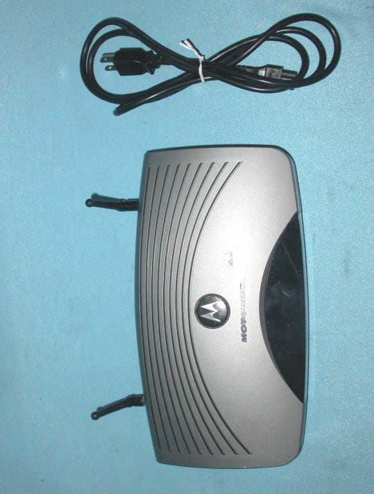
Click to zoom
Application Details
- Equipment Class
- DTS - Digital Transmission System
- Date of Grant
- Mar 18, 2004
- Application Purpose
- Original Equipment
- Date of Application
- Mar 18, 2004
- Equipment Note
- Wireless Cable Modem Gateway
- Frequency Range
- 2412.00000000 - 2462.00000000
- Company
- Motorola Mobility LLC
- Country
- United States
Documents & Files
Document Text
Text extracted from the exhibit documents filed with the FCC. Open a document above to read the original.
Users Manual
User Guide SBG940 Wireless Cable Modem Gateway iiSBG940 User Guide Home X ExitPrint Overview Installation Troubleshooting ContactFAQ Specifications Glossary License Configuration: Basic Gateway TCP/IP Wireless USB WARNING: TO PREVENT FIRE OR SHOCK HAZARD, DO NOT EXPOSE THIS PRODUCT TO RAIN OR MOISTURE. THE UNIT MUST NOT BE EXPOSED TO DRIPPING OR SPLASHING. DO NOT PLACE OBJECTS FILLED WITH LIQUIDS, SUCH AS VASES, ON THE UNIT. CAUTION: TO PREVENT ELECTRIC SHOCK, THIS EQUIPMENT MAY REQUIRE A GROUNDING CONDUCTOR IN THE LINE CORD. CONNECT THE UNIT TO A GROUNDING TYPE AC WALL OUTLET USING THE POWER CORD SUPPLIED WITH THE UNIT. CAUTION: THIS PRODUCT WAS QUALIFIED UNDER TEST CONDITIONS THAT INCLUDED THE USE OF THE SUPPLIED CABLES BETWEEN SYSTEMS COMPONENTS. TO ENSURE REGULATORY AND SAFETY COMPLIANCE, USE ONLY THE PROVIDED POWER AND INTERFACE CABLES AND INSTALL THEM PROPERLY. CAUTION: DIFFERENT TYPES OF CORD SETS MAY BE USED FOR CONNECTIONS TO THE MAIN SUPPLY CIRCUIT. USE ONLY A MAIN LINE CORD THAT COMPLIES WITH ALL APPLICABLE PRODUCT SAFETY REQUIREMENTS OF THE COUNTRY OF USE. CAUTION: INSTALLATION OF THIS PRODUCT MUST BE IN ACCORDANCE WITH NATIONAL WIRING CODES AND CONFORM TO LOCAL REGULATIONS. CAUTION: DO NOT OPEN THE UNIT. DO NOT PERFORM ANY SERVICING OTHER THAN THAT CONTAINED IN THE INSTALLATION AND TROUBLESHOOTING INSTRUCTIONS. REFER ALL SERVICING TO QUALIFIED SERVICE PERSONNEL. CAUTION: CHANGES AND MODIFICATIONS NOT EXPRESSLY APPROVED BY MOTOROLA FOR COMPLIANCE COULD VOID USER’S AUTHORITY TO OPERATE THE EQUIPMENT. When using this device, basic safety precautions should always be followed to reduce the risk of fire, electric shock and injury to persons, including the following: •Read all of the instructions listed here and/or in the user manual before you operate this equipment. Give particular attention to all safety precautions. Retain the instructions for future reference. •This device must be installed and used in strict accordance with manufacturer’s instructions as described in the user documentation that comes with the product. •Comply with all warning and caution statements in the instructions. Observe all warning and caution symbols that are affixed to this equipment. •Comply with all instructions that accompany this equipment. •Do not overload outlets or extension cords, as this can result in a risk of fire or electric shock. Overloaded AC outlets, extension cords, frayed power cords, damaged or cracked wire insulation, and broken plugs are dangerous. They may result in a shock or fire hazard. •Route power supply cords so that they are not likely to be walked on or pinched by items placed upon or against them. Pay particular attention to cords where they are attached to plugs and convenience receptacles, and examine the point where they exit from the product. •Place this equipment in a location that is close enough to an electrical outlet to accommodate the length of the power cord. •Place unit to allow for easy access when disconnecting the power cord of the device from the AC wall outlet. •Do not connect the plug into an extension cord, receptacle, other outlet unless the plug can be fully inserted with no part of the blades exposed. •Place this equipment on a stable surface. iiiSBG940 User Guide Home X ExitPrint Overview Installation Troubleshooting ContactFAQ Specifications Glossary License Configuration: Basic Gateway TCP/IP Wireless USB •Postpone cable modem installation until there is no risk of thunderstorm or lightning activity in the area. •Avoid using this product during an electrical storm. There may be a risk of electric shock from lightning. For added protection for this product during a lightning storm, or when it is left unattended and unused for long periods of time, unplug it from the wall outlet, and disconnect the cable system. This will prevent damage to the product due to lightning and power surges. •It is recommended that the customer install an AC surge protector in the AC outlet to which this device is connected. This is to avoid damaging the equipment by local lightning strikes and other electrical surges. •Do not cover the device, or block the airflow to the device with any other objects. Keep the device away from excessive heat and humidity and keep the device free from vibration and dust. •Wipe the unit with a clean, dry cloth. Never use cleaning fluid or similar chemicals. Do not spray cleaners directly on the unit or use forced air to remove dust. •Avoid damaging the cable modem with static by touching the coaxial cable when it is attached to the earth grounded coaxial cable TV wall outlet. •Always first touch the coaxial cable connector on the cable modem when disconnecting or re-connecting USB or Ethernet cable from the cable modem or the user’s PC. •Operate this product only from the type of power source indicated on the product’s marking label. If you are not sure of the type of power supplied to your home, consult your dealer or local power company. •Upon completion of any service or repairs to this product, ask the service technician to perform safety checks to determine that the product is in safe operating condition. Be sure that the outside cable system is grounded, so as to provide some protection against voltage surges and built-up static charges. Article 820-20 of the NEC (Section 54, Part I of the Canadian Electrical Code) provides guidelines for proper grounding and, in particular, specifies the CATV cable ground shall be connected in the grounding system of the building, as close to the point of cable entry as practical. Apparaten skall anslutas till jordat uttag när den ansluts ett näverk. FCC Compliance Class B Digital Device This device complies with part 15 of the FCC Rules. Operation is subject to the following two conditions: (1) This device may not cause harmful interference, and (2) this device must accept any interference received, including interference that may cause undesired operation. Note: This equipment has been tested a…
Text truncated - open the document above for the full version.
Users Manual
56SBG940 User Guide Home X ExitPrint Overview Installation Troubleshooting ContactFAQ Specifications Glossary License Configuration: Basic Gateway TCP/IP Wireless USB 4Click Local Area Connection number. The value of number varies from system to system. The Local Area Connection number Status window is displayed: 5Click Properties. Information similar to the following window is displayed: 6If Internet Protocol (TCP/IP) is in the list of components, TCP/IP is installed. You can skip to step 10. If Internet Protocol (TCP/IP) is not in the list, click Install. The Select Network Component Type window is displayed: 57SBG940 User Guide Home X ExitPrint Overview Installation Troubleshooting ContactFAQ Specifications Glossary License Configuration: Basic Gateway TCP/IP Wireless USB 7Click Protocol on the Select Network Component Type window and click Add. The Select Network Protocol window is displayed: 8Click Internet Protocol (TCP/IP). 9Click OK. The Local Area Connection number Properties window is re-displayed. 10Be sure the box next to Internet Protocol (TCP/IP) is selected. 58SBG940 User Guide Home X ExitPrint Overview Installation Troubleshooting ContactFAQ Specifications Glossary License Configuration: Basic Gateway TCP/IP Wireless USB 11Click Properties. The Internet Protocol (TCP/IP) Properties window is displayed: 12Be sure Obtain IP address automatically and Obtain DNS server address automatically are selected. 13Click OK to accept the TCP/IP settings. 14Click Close to close the Local Area Connection number Properties window. 15Click OK when prompted to restart the computer and click OK again. When you complete the TCP/IP configuration, go to “Verifying the IP Address in Windows 2000 or Windows XP”. 59SBG940 User Guide Home X ExitPrint Overview Installation Troubleshooting ContactFAQ Specifications Glossary License Configuration: Basic Gateway TCP/IP Wireless USB Configuring TCP/IP in Windows XP 1On the Windows desktop, click Start to display the Start window: 2Click Control Panel to display the Control Panel window. The display varies, depending on the Windows XP view options. If the display is a Category view as shown below, continue with step 3. Otherwise, skip to step 5. 60SBG940 User Guide Home X ExitPrint Overview Installation Troubleshooting ContactFAQ Specifications Glossary License Configuration: Basic Gateway TCP/IP Wireless USB 3Click Network and Internet Connections to display the Network and Internet Connections window: 4Click Network Connections to display the LAN or High-speed Internet connections. Skip to step 7. 5If a classic view similar to below is displayed: 6Double-click Network Connections to display the LAN or High-speed Internet connections. 61SBG940 User Guide Home X ExitPrint Overview Installation Troubleshooting ContactFAQ Specifications Glossary License Configuration: Basic Gateway TCP/IP Wireless USB 7Right-click on the network connection. If more than one connection is displayed, be sure to select the one for your network interface: 8Select Properties from the pop-up menu to display the Local Area Connection Properties window: 9On the Local Area Connection Properties window, be sure Internet Protocol (TCP/IP) is selected. If it is not selected, select it. 62SBG940 User Guide Home X ExitPrint Overview Installation Troubleshooting ContactFAQ Specifications Glossary License Configuration: Basic Gateway TCP/IP Wireless USB 10Select Internet Protocol (TCP/IP) and click Properties to display the Internet Protocol (TCP/IP) Properties window: 11Verify that the settings are correct, as shown above. 12Click OK to close the TCP/IP Properties window. 13Click OK to close the Local Area Connection Properties window. When you complete the TCP/IP configuration, go to “Verifying the IP Address in Windows 2000 or Windows XP”. 63SBG940 User Guide Home X ExitPrint Overview Installation Troubleshooting ContactFAQ Specifications Glossary License Configuration: Basic Gateway TCP/IP Wireless USB Verifying the IP Address in Windows 95, Windows 98, or Windows Me To check the IP address: 1On the Windows Desktop, click Start. 2Select Run. The Run window is displayed. 3Type winipcfg.exe and click OK. The IP Configuration window is displayed. The Ethernet Adapter Information field will vary depending on the system, as shown in the following examples: The values for Adapter Address, IP Address, Subnet Mask, and Default Gateway on the PC will be different than in the images. In Windows 98, if “Autoconfiguration” is displayed before the IP Address as in the following image, call your service provider. 4Select the adapter name — the Ethernet card or USB device. 5Click Renew. 6Click OK after the system displays an IP address. If after performing this procedure the computer cannot access the Internet, call your cable provider for help. 64SBG940 User Guide Home X ExitPrint Overview Installation Troubleshooting ContactFAQ Specifications Glossary License Configuration: Basic Gateway TCP/IP Wireless USB Verifying the IP Address in Windows 2000 or Windows XP To check the IP address: 1On the Windows Desktop, click Start. 2Select Run. The Run window is displayed. 3Type cmd and click OK to display a command prompt window. 4Type ipconfig and press ENTER to display the IP configuration. A display similar to the following indicates a normal configuration: If an Autoconfiguration IP Address is displayed as in the following window, there is an incorrect connection between the PC and the SBG940 or there are cable network problems. Check the cable connections and determine if you can view cable-TV channels on your television: After verifying the cable connections and proper cable-TV operation, renew the IP address. 65SBG940 User Guide Home X ExitPrint Overview Installation Troubleshooting ContactFAQ Specifications Glossary License Configuration: Basic Gateway TCP/IP Wireless USB To renew the IP address: 1Type ipconfig /renew and press ENTER. If a valid IP address is displayed as shown, Internet access s…
Text truncated - open the document above for the full version.
Attestation Statements
Mototech Inc. No. 9, Park Avenue II, Science-based Industrial Park, Hsin-Chu, Taiwan, R.O.C. Attestation FCC ID :IHDSBG940-1 Product :Wireless Cable Modem Gateway Model : SBG940/SBG940i SBG940E SBG940 Diagnostic SBG940E Diagnostic Statements: We don’t provide with any controls or software to allow operation outside the USA frequency band for all future applications when we sell this product in USA. Sincerely,
Cover Letter(s)
Mototech Inc. No. 9, Park Avenue II, Science-based Industrial Park, Hsin-Chu, Taiwan, R.O.C. Confidentiality Request FCC ID :IHDSBG940-1 Product :Wireless Cable Modem Gateway Model : SBG940/SBG940i SBG940E SBG940 Diagnostic SBG940E Diagnostic Pursuant to Sections 0.457 and 0.459 of the Commission’s Rules, the Applicant hereby requests confidential treatment of information accompanying this Application as outlined below. Schematics / Block Diagram The above materials contain trade secrets and proprietary information not customarily released to the public. The public disclosure of these matters might be harmful to the Applicant and provide unjustified benefits to its competitors. The Applicant understands that pursuant to Rule 0.457, disclosure of this Application And all accompanying documentation will not be made before the date of the Grant for this application. Sincerely,
External Photos
Company: Mototech Inc. Page : 1 of 21 Product: Wireless Cable Modem Gateway Model: SBG940 Diagnostic Company: Mototech Inc. Page : 2 of 21 Product: Wireless Cable Modem Gateway Model: SBG940 Diagnostic Company: Mototech Inc. Page : 3 of 21 Product: Wireless Cable Modem Gateway Model: SBG940 Diagnostic Company: Mototech Inc. Page : 4 of 21 Product: Wireless Cable Modem Gateway Model: SBG940 Diagnostic Company: Mototech Inc. Page : 5 of 21 Product: Wireless Cable Modem Gateway Model: SBG940 Diagnostic Company: Mototech Inc. Page : 6 of 21 Product: Wireless Cable Modem Gateway Model: SBG940 Diagnostic
External Photos
Company: Mototech Inc. Page: 1 of 20 Product: Wireless Cable Modem Gateway Model: SBG940/SBG940i Company: Mototech Inc. Page: 2 of 20 Product: Wireless Cable Modem Gateway Model: SBG940/SBG940i Company: Mototech Inc. Page: 3 of 20 Product: Wireless Cable Modem Gateway Model: SBG940/SBG940i Company: Mototech Inc. Page: 4 of 20 Product: Wireless Cable Modem Gateway Model: SBG940/SBG940i Company: Mototech Inc. Page: 5 of 20 Product: Wireless Cable Modem Gateway Model: SBG940/SBG940i Company: Mototech Inc. Page: 6 of 20 Product: Wireless Cable Modem Gateway Model: SBG940/SBG940i
External Photos
Company: Mototech Inc. Page: 1 of 20 Product: Wireless Cable Modem Gateway Model: SBG940E Diagnostic Company: Mototech Inc. Page: 2 of 20 Product: Wireless Cable Modem Gateway Model: SBG940E Diagnostic Company: Mototech Inc. Page: 3 of 20 Product: Wireless Cable Modem Gateway Model: SBG940E Diagnostic Company: Mototech Inc. Page: 4 of 20 Product: Wireless Cable Modem Gateway Model: SBG940E Diagnostic Company: Mototech Inc. Page: 5 of 20 Product: Wireless Cable Modem Gateway Model: SBG940E Diagnostic Company: Mototech Inc. Page: 6 of 20 Product: Wireless Cable Modem Gateway Model: SBG940E Diagnostic
External Photos
Company: Mototech Inc. Page: 1 of 20 Product: Wireless cable modem Gateway Model: SBG940E Company: Mototech Inc. Page: 2 of 20 Product: Wireless cable modem Gateway Model: SBG940E Company: Mototech Inc. Page: 3 of 20 Product: Wireless cable modem Gateway Model: SBG940E Company: Mototech Inc. Page: 4 of 20 Product: Wireless cable modem Gateway Model: SBG940E Company: Mototech Inc. Page: 5 of 20 Product: Wireless cable modem Gateway Model: SBG940E Company: Mototech Inc. Page: 6 of 20 Product: Wireless cable modem Gateway Model: SBG940E
ID Label/Location Info
Wireless Cable Modem Gateway Model No: SBG940/SBG940i SBG940E SBG940 DiagnosticSBG940E Diagnostic FCC IDIHDSBG940-1 This device complies with part 15 of the FCC Rules. Operation is subject to the following two conditions: [1] this device may not cause harmful interference and [2] this device must accept any interference received, including interference that may cause undesired operation. S/N Made in Taiwan
Internal Photos
Company: Mototech Inc. Page : 7 of 21 Product: Wireless Cable Modem Gateway Model: SBG940 Diagnostic Company: Mototech Inc. Page : 8 of 21 Product: Wireless Cable Modem Gateway Model: SBG940 Diagnostic Company: Mototech Inc. Page : 9 of 21 Product: Wireless Cable Modem Gateway Model: SBG940 Diagnostic Company: Mototech Inc. Page : 10 of 21 Product: Wireless Cable Modem Gateway Model: SBG940 Diagnostic Company: Mototech Inc. Page : 11 of 21 Product: Wireless Cable Modem Gateway Model: SBG940 Diagnostic Company: Mototech Inc. Page : 12 of 21 Product: Wireless Cable Modem Gateway Model: SBG940 Diagnostic Company: Mototech Inc. Page : 13 of 21 Product: Wireless Cable Modem Gateway Model: SBG940 Diagnostic Company: Mototech Inc. Page : 14 of 21 Product: Wireless Cable Modem Gateway Model: SBG940 Diagnostic Company: Mototech Inc. Page : 15 of 21 Product: Wireless Cable Modem Gateway Model: SBG940 Diagnostic Company: Mototech Inc. Page : 16 of 21 Product: Wireless Cable Modem Gateway Model: SBG940 Diagnostic Company: Mototech Inc. Page : 17 of 21 Product: Wireless Cable Modem Gateway Model: SBG940 Diagnostic Company: Mototech Inc. Page : 18 of 21 Product: Wireless Cable Modem Gateway Model: SBG940 Diagnostic Company: Mototech Inc. Page : 19 of 21 Product: Wireless Cable Modem Gateway Model: SBG940 Diagnostic Company: Mototech Inc. Page : 20 of 21 Product: Wireless Cable Modem Gateway Model: SBG940 Diagnostic Company: Mototech Inc. Page : 21 of 21 Product: Wireless Cable Modem Gateway Model: SBG940 Diagnostic
Internal Photos
Company: Mototech Inc. Page: 7 of 20 Product: Wireless Cable Modem Gateway Model: SBG940/SBG940i Company: Mototech Inc. Page: 8 of 20 Product: Wireless Cable Modem Gateway Model: SBG940/SBG940i Company: Mototech Inc. Page: 9 of 20 Product: Wireless Cable Modem Gateway Model: SBG940/SBG940i Company: Mototech Inc. Page: 10 of 20 Product: Wireless Cable Modem Gateway Model: SBG940/SBG940i Company: Mototech Inc. Page: 11 of 20 Product: Wireless Cable Modem Gateway Model: SBG940/SBG940i Company: Mototech Inc. Page: 12 of 20 Product: Wireless Cable Modem Gateway Model: SBG940/SBG940i Company: Mototech Inc. Page: 13 of 20 Product: Wireless Cable Modem Gateway Model: SBG940/SBG940i Company: Mototech Inc. Page: 14 of 20 Product: Wireless Cable Modem Gateway Model: SBG940/SBG940i Company: Mototech Inc. Page: 15 of 20 Product: Wireless Cable Modem Gateway Model: SBG940/SBG940i Company: Mototech Inc. Page: 16 of 20 Product: Wireless Cable Modem Gateway Model: SBG940/SBG940i Company: Mototech Inc. Page: 17 of 20 Product: Wireless Cable Modem Gateway Model: SBG940/SBG940i Company: Mototech Inc. Page: 18 of 20 Product: Wireless Cable Modem Gateway Model: SBG940/SBG940i Company: Mototech Inc. Page: 19 of 20 Product: Wireless Cable Modem Gateway Model: SBG940/SBG940i Company: Mototech Inc. Page: 20 of 20 Product: Wireless Cable Modem Gateway Model: SBG940/SBG940i
Internal Photos
Company: Mototech Inc. Page: 7 of 20 Product: Wireless Cable Modem Gateway Model: SBG940E Diagnostic Company: Mototech Inc. Page: 8 of 20 Product: Wireless Cable Modem Gateway Model: SBG940E Diagnostic Company: Mototech Inc. Page: 9 of 20 Product: Wireless Cable Modem Gateway Model: SBG940E Diagnostic Company: Mototech Inc. Page: 1 of 20 Product: Wireless Cable Modem Gateway Model: SBG940E Diagnostic Company: Mototech Inc. Page: 11 of 20 Product: Wireless Cable Modem Gateway Model: SBG940E Diagnostic Company: Mototech Inc. Page: 12 of 20 Product: W Wireless Cable Modem Gateway Model: SBG940E Diagnostic Company: Mototech Inc. Page: 13 of 20 Product: Wireless Cable Modem Gateway Model: SBG940E Diagnostic Company: Mototech Inc. Page: 14 of 20 Product: Wireless Cable Modem Gateway Model: SBG940E Diagnostic Company: Mototech Inc. Page: 15 of 20 Product: Wireless Cable Modem Gateway Model: SBG940E Diagnostic Company: Mototech Inc. Page: 16 of 20 Product: Wireless Cable Modem Gateway Model: SBG940E Diagnostic Company: Mototech Inc. Page: 17 of 20 Product: Wireless Cable Modem Gateway Model: SBG940E Diagnostic Company: Mototech Inc. Page: 18 of 20 Product: Wireless Cable Modem Gateway Model: SBG940E Diagnostic Company: Mototech Inc. Page: 19 of 20 Product: Wireless Cable Modem Gateway Model: SBG940E Diagnostic Company: Mototech Inc. Page: 20 of 20 Product: Wireless Cable Modem Gateway Model: SBG940E Diagnostic
Internal Photos
Company: Mototech Inc. Page: 7 of 20 Product: Wireless cable modem Gateway Model: SBG940E Company: Mototech Inc. Page: 8 of 20 Product: Wireless cable modem Gateway Model: SBG940E Company: Mototech Inc. Page: 9 of 20 Product: Wireless cable modem Gateway Model: SBG940E Company: Mototech Inc. Page: 10 of 20 Product: Wireless cable modem Gateway Model: SBG940E Company: Mototech Inc. Page: 11 of 20 Product: Wireless cable modem Gateway Model: SBG940E Company: Mototech Inc. Page: 12 of 20 Product: Wireless cable modem Gateway Model: SBG940E Company: Mototech Inc. Page: 13 of 20 Product: Wireless cable modem Gateway Model: SBG940E Company: Mototech Inc. Page: 14 of 20 Product: Wireless cable modem Gateway Model: SBG940E Company: Mototech Inc. Page: 15 of 20 Product: Wireless cable modem Gateway Model: SBG940E Company: Mototech Inc. Page: 16 of 20 Product: Wireless cable modem Gateway Model: SBG940E Company: Mototech Inc. Page: 17 of 20 Product: Wireless cable modem Gateway Model: SBG940E Company: Mototech Inc. Page: 18 of 20 Product: Wireless cable modem Gateway Model: SBG940E Company: Mototech Inc. Page: 19 of 20 Product: Wireless cable modem Gateway Model: SBG940E Company: Mototech Inc. Page: 20 of 20 Product: Wireless cable modem Gateway Model: SBG940E
Operational Description
Description of Operation EUT is a Wireless Cable Modem Gateway with 11 channels. This device provided four kind of transmitting speed 1,2,5.5 and 11Mbps. The device of RF carrier is DQPSK,DB PSK and CCK.The device adapts direct sequence spread spectrum modulation. The Connector antenna was scolded on PCB provided diversity function to improve the receiving function.This Wireless Cable Modem Gateway is an IEEE 802.11b&g Wireless Gateway cable modem. It allows your computer to connect to a wireless network and to share resources, such as files or printers without being bound to the network wires. Operation in 2.4GHz Direct Sequence Spread Spectrum (D.S.S.S) Orthogonal Frequency Division Multiplex (O.F.D.M) radio transmission, the Wireless Cable Modem Gateway transfers data at speeds up to 64/128-bit Wired Equivalent Protection(WEP) algorithm is used. In addition, its standard compliance ensures that it can communicate with any 802.11bg network.
RF Exposure Info
Ecom Sertech Corp. Rm. 258, Bldg. 17, NO.195, Sec. 4 Chung Hsing Rd.,Chu -Tung Chen, Hsinchu, Taiwan 310, R.O.C TEL:886 - 3 - 5918012 FAX : 886 - 3 - 5825720 FCC ID IHDSBG940-1 Report No.EC04-01-053FRF Page 1 of 2 . RF EXPOSURE EVALUATION According to FCC 1.1310 : The criteria listed in the following table shall be used to evaluate the environment impact of human exposure to radio frequency (RF) radiation as specified in 1.1307(b) LIMITS FOR MAXIMUM PERMISSIBLE EXPOSURE (MPE) Frequency Range (MHz) Electric Field Strength (V/m) Magnetic Field Strength (A/m) Power Density (mW/cm 2 ) Average Time (A) Limits for Occupational / Control Exposures 300-1,500 -- -- F/300 6 1,500-100,000 -- -- 5 6 (B) Limits for General Population / Uncontrol Exposures 300-1,500 -- -- F/1500 6 1,500-100,000 -- -- 1 30 1 Friis Formula Friis transmission formula : Pd = (Pout*G)/(4*pi*r 2 ) Where Pd = power density in mW/cm 2 Pout = output power to antenna in mW G = gain of antenna in linear scale Pi = 3.1416 R = distance between observation point and center of the radiator in cm Pd id the limit of MPE, 1 mW/cm2. If we know the maximum gain of the antenna and the total power input to the antenna, through the calculation, we will know the distance r where the MPE limit is reached. 2 EUT Operating Condition A software provided by client enabled the EUT to transmit and receive data at lowest, middle and highest channel individually. 3 Test Result of RF Exposure Evaluation Test Item RF Exposure Evaluation Data Test Mode Normal Operation Ecom Sertech Corp. Rm. 258, Bldg. 17, NO.195, Sec. 4 Chung Hsing Rd.,Chu -Tung Chen, Hsinchu, Taiwan 310, R.O.C TEL:886 - 3 - 5918012 FAX : 886 - 3 - 5825720 FCC ID IHDSBG940-1 Report No.EC04-01-053FRF Page 2 of 2 3.1 Antenna Gain Antenna GainThe maximum Gain measured in fully anechoic chamber is 1dBi5dBi 6dBi and 9dBi linear scale. 3.2 Maximum PEAK Output Power Refer to 5.6 Maximum peak Output Power is : 14.7 dBm (for 802.11b mode CH6), 13.1 dBm (for 802.11g mode CH6). 3.3 Output Power into Antenna & RF Exposure Evaluation Distance Outpower (max) (dBm) Cable length to antenna (m) Min Cable Loss (dB) Input Power to Antenna (dBm) Antenna Model Antenna Type Antenna Gain (dBi) EIRP (dBm) EIRP (Watts) MPE Distance (cm) Pd at 20cm (mW/cm^2) Comments 14.7 1.6 0 14.7 CAF28927 Omnidirctional1 15.7 0.0371541.72 0.007392 Minimum separation shall be 20cm 14.7 1.6 1 13.7 CAF94554 Bi-directional5 18.7 0.0741312.43 0.014748 Minimum separation shall be 20cm 14.7 1.6 1 13.7 CAF94519 Omnidirctional6 19.7 0.0933252.73 0.018566 Minimum separation shall be 20cm 14.7 1.6 1 13.7 CAF95950 Directional9 22.7 0.1862093.85 0.037045 Minimum separation shall be 20cm Note : 1. For 802.11b Mode. 2. The power density Pd (4 th column) at a distance of 20cm calculated from the Friis transmission formula is far below the limit of 1 mW/cm 2 . The EUT is classified as mobile product. So, RF exposure limit warning or SAR test are not required. Outpower (max) (dBm) Cable length to antenna (m) Min Cable Loss (dB) Input Power to Antenna (dBm) Antenna Model Antenna Type Antenna Gain (dBi) EIRP (dBm) EIRP (Watts) MPE Distance (cm) Pd at 20cm (mW/cm^2) Comments 13.1 1.6 0 13.1 CAF28927 Omnidirctional1 14.1 0.0257041.43 0.005114 Minimum separation shall be 20cm 13.1 1.6 1 12.1 CAF94554 Bi-directional5 17.1 0.0512862.02 0.010203 Minimum separation shall be 20cm 13.1 1.6 1 12.1 CAF94519 Omnidirctional6 18.1 0.0645652.27 0.012845 Minimum separation shall be 20cm 13.1 1.6 1 12.1 CAF95950 Directional9 21.1 0.1288253.20 0.025629 Minimum separation shall be 20cm Note : 1. For 802.11g Mode. 2. The power density Pd (4 th column) at a distance of 20cm calculated from the Friis transmission formula is far below the limit of 1 mW/cm 2 . The EUT is classified as mobile product. So, RF exposure limit warning or SAR test are not required.
Test Report
Ecom Sertech Corp. Rm. 258, Bldg. 17, NO.195, Sec. 4 Chung Hsing Rd.,Chu -Tung Chen, Hsinchu, Taiwan 310, R.O.C TEL:886 - 3 - 5918012 FAX : 886 - 3 - 5825720 FCC ID IHDSBG940-1 Report No.EC04-01-053FRF Page 1 of 153 RF TEST REPORT Product Name Wireless Cable Modem Gateway Model Number SBG940/SBG940i SBG940E SBG940 Diagnostic SBG940E Diagnostic Applicant Mototech Inc. Address No. 9, Park Avenue II, Science-based Industrial Park, Hsin-Chu, Taiwan, R.O.C. Date Received Jan. 29, 2004 Date Tested Jan. 29 ~ Mar. 02, 2004 Notes 1. This report will be invalid if duplicated or photocopied in part. 2. This report refers only to the specimen(s) submitted to testing, and be invalid as seperately used. 3. This report is invalid without examination stamp and signature of this institute. 4. The tested specimen(s) will be preserved for thirty days from the data issued. 5. The report must not be used to claim product certification, approval, or endorsement by NVLAP, NIST, or any agency of the federal government. Ecom Sertech Corp. Rm. 258, Bldg. 17, NO.195, Sec. 4 Chung Hsing Rd.,Chu -Tung Chen, Hsinchu, Taiwan 310, R.O.C TEL:886 - 3 - 5918012 FAX : 886 - 3 - 5825720 FCC ID IHDSBG940-1 Report No.EC04-01-053FRF Page 2 of 153 Test Report Certification Product Name : Wireless Cable Modem Gateway Model Number : SBG940/SBG940iSBG940ESBG940 Diagnostic SBG940E Diagnostic Applicant : Mototech Inc. Measurement Standard : 47 CFR Part 15, Subpart B and Subpart C (Section 15.247), ANSI C63.4-2001 WE HEREBY CERTIFY THAT: The measurements shown in the attachment were made in accordance with the procedures indicated, and the energy emitted by the equipment was found to be within the limits applicable. We assume full responsibility for the accuracy and completeness of these measurements and vouch for the qualifications of all persons taking them. Ecom Sertech Corp. Rm. 258, Bldg. 17, NO.195, Sec. 4 Chung Hsing Rd.,Chu -Tung Chen, Hsinchu, Taiwan 310, R.O.C TEL:886 - 3 - 5918012 FAX : 886 - 3 - 5825720 FCC ID IHDSBG940-1 Report No.EC04-01-053FRF Page 3 of 153 TABLE OF CONTENTS TITLE PAGE NO. 1. GENERAL INFORMATION ................................................................................................ 5 1.1 General Statement ........................................................................................................................... 5 1.2 General Description of EUT & Power ............................................................................................ 5 1.3 Description of Peripherals............................................................................................................... 6 1.4 EUT & Peripherals Setup Diagram................................................................................................. 7 1.5 EUT Operating Condition ............................................................................................................... 8 1.6 Description of Test Site................................................................................................................... 8 1.7 Summary of Test Results ................................................................................................................ 9 2. CONDUCTED POWERLINE TEST.................................................................................... 10 2.1 Test Equipments.............................................................................................................................. 10 2.2 Test Setup..................................................................................…
Text truncated - open the document above for the full version.
Contact Information
Applicant
Jeff Narducci(Director Product Compliance)
Test Firm
ECOM Sertech Corp.C. Wu
Technical Specifications
| # | Rule Parts | Frequency Range | Power Output |
|---|---|---|---|
| 1 | 15C | 2.41 GHz - 2.46 GHz | 29.51 mW |
Other Applications from Motorola Mobility LLC
IHDT56AW9
May 12, 2026Smart Watch
Equipment Class
NII - Unlicensed National Information Infrastructure TXIHDT56AW5
Apr 08, 2026Mobile Cellular Phone
Equipment Class
DTS - Digital Transmission SystemIHDT56AW6
Mar 18, 2026Smart Watch
Equipment Class
JBP - Part 15 Class B Computing Device PeripheralIHDT56AX4
Mar 17, 2026Mobile Cellular Phone
Equipment Class
PCE - PCS Licensed Transmitter held to earIHDT56AW3
Mar 03, 2026Mobile Cellular Phone
Equipment Class
6XD - 15E 6 GHz Low Power Indoor Client