IHDT56AA1Portable Cellular Transceiver
Motorola Mobility LLC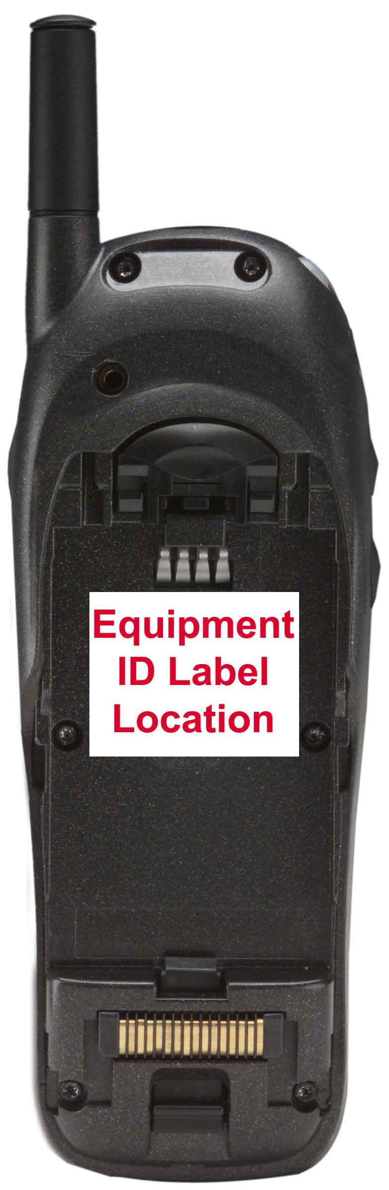
Click to zoom
Application Details
- Equipment Class
- TNE - Licensed Non-Broadcast Transmitter Held to Ear
- Date of Grant
- Aug 09, 2000
- Application Purpose
- Original Equipment
- Date of Application
- Jun 18, 2000
- Equipment Note
- Portable Cellular Transceiver
- Frequency Range
- 1851.25000000 - 1908.75000000
- Company
- Motorola Mobility LLC
- Country
- United States
Documents & Files
Document Text
Text extracted from the exhibit documents filed with the FCC. Open a document above to read the original.
Users Manual
APPLICANT: MOTOROLA, INC.FCC ID: IHDT56AA1 EXHIBIT 8 INSTRUCTION MANUAL A preliminary draft copy of the Users Manual follows: CDMA Panther Wireless Telephone Basic User’s Guide Preliminary Draft June 16, 2000 i Contents Contents Safety Information . . . . . . . . . . . . . . . . . . . . . . . . . . . . . . . . . . 3 Getting Started . . . . . . . . . . . . . . . . . . . . . . . . . . . . . . . . . . . . . 10 Opening the Box . . . . . . . . . . . . . . . . . . . . . . . . . . . . . . . . . . . . 10 Battery . . . . . . . . . . . . . . . . . . . . . . . . . . . . . . . . . . . . . . . . . . . . 11 Turning On Your Phone . . . . . . . . . . . . . . . . . . . . . . . . . . . . . . 12 Placing a Call . . . . . . . . . . . . . . . . . . . . . . . . . . . . . . . . . . . . . . 13 Ending a Call . . . . . . . . . . . . . . . . . . . . . . . . . . . . . . . . . . . . . . 13 Redialing a Number . . . . . . . . . . . . . . . . . . . . . . . . . . . . . . . . . 14 Receiving a Call . . . . . . . . . . . . . . . . . . . . . . . . . . . . . . . . . . . . 14 Viewing Your Phone Number . . . . . . . . . . . . . . . . . . . . . . . . . . 14 Learning More Tasks . . . . . . . . . . . . . . . . . . . . . . . . . . . . . . . 15 Navigating to Features . . . . . . . . . . . . . . . . . . . . . . . . . . . . . . . 15 Using Menu Features . . . . . . . . . . . . . . . . . . . . . . . . . . . . . . . . 19 Entering Text . . . . . . . . . . . . . . . . . . . . . . . . . . . . . . . . . . . . . . 22 Storing an Entry in the Phonebook . . . . . . . . . . . . . . . . . . . . . 25 Using Text Messages . . . . . . . . . . . . . . . . . . . . . . . . . . . . . . . . . 29 Using Voicemail . . . . . . . . . . . . . . . . . . . . . . . . . . . . . . . . . . . . 32 Locking and Unlocking Your Phone . . . . . . . . . . . . . . . . . . . . 33 Caller ID . . . . . . . . . . . . . . . . . . . . . . . . . . . . . . . . . . . . . . . . . . 35 Automatic Redial . . . . . . . . . . . . . . . . . . . . . . . . . . . . . . . . . . . 35 Call Waiting . . . . . . . . . . . . . . . . . . . . . . . . . . . . . . . . . . . . . . . 36 Unanswered Calls . . . . . . . . . . . . . . . . . . . . . . . . . . . . . . . . . . . 36 Dialing Emergency Numbers . . . . . . . . . . . . . . . . . . . . . . . . . 37 Additional Dialing Features . . . . . . . . . . . . . . . . . . . . . . . . . . . 37 Contents ii Using In-Call Features . . . . . . . . . . . . . . . . . . . . . . . . . . . . . . . 39 Phone Fundamentals . . . . . . . . . . . . . . . . . . . . . . . . . . . . . . . 40 Phone Diagram . . . . . . . . . . . . . . . . . . . . . . . . . . . . . . . . . . . . 40 Display . . . . . . . . . . . . . . . . . . . . . . . . . . . . . . . . . . . . . . . . . . . 41 Status Light . . . . . . . . . . . . . . . . . . . . . . . . . . . . . . . . . . . . . . . 43 Volume Keys . . . . . . . . . . . . . . . . . . . . . . . . . . . . . . . . . . . . . . . 44 Battery Use . . . . . . . . . . . . . . . . . . . . . . . . . . . . . . . . . . . . . . . . 44 When You’re Ready to Do More . . . . . . . . . . . . . . . . . . . . 46 Menu Map . . . . . . . . . . . . . . . . . . . . . . . . . . . . . . . . . . . . . . . . 46 Menu Feature Descriptions . . . . . . . . . . . . . . . . . . . . . . . . . . . 47 Conference Call . . . . . . . . . . . . . . . . . . . . . . . . . . . . . . . . . . . . 54 VoiceNotes . . . . . . . . . . . . . . . . . . . . . . . . . . . . . . . . . . . . . . . . . 55 Datebook . . . . . . . . . . . . . . . . . . . . . . . . . . . . . . . . . . . . . . . . . . 59 Configuring Settings . . . . . . . . . . . . . . . . . . . . . . . . . . . . . . . . 62 Troubleshooting . . . . . . . . . . . . . . . . . . . . . . . . . . . . . . . . . . . 68 FDA Update . . . . . . . . . . . . . . . . . . . . . . . . . . . . . . . . . . . . . . . . 75 Index . . . . . . . . . . . . . . . . . . . . . . . . . . . . . . . . . . . . . . . . . . . . . . 85 Patent Information . . . . . . . . . . . . . . . . . . . . . . . . . . . . . . . . . 92 3 Safety Information Safety Information Important: Read this information before using your wireless handheld phone. Exposure to Radio Frequency Signals Your wireless handheld portable telephone is a low power radio transmitter and receiver. When it is ON, it receives and also sends out radio frequency (RF) signals. In August 1996, The Federal Communications Commission (FCC) adopted RF exposure guidelines with safety levels for handheld wireless phones. Those guidelines are consistent with safety standards previously set by both U.S. and international standards bodies: • American National Standards Institute (ANSI) IEEE. C95. 1-1992 • National Council on Radiation Protection and Measurement (NCRP). Report 86 • International Commission on Non-Ionizing Radiation Protection (ICNIRP) 1996 • Ministry of Health (Canada), Safety Code 6 Those standards were based on comprehensive and periodic evaluations of the relevant scientific literature. For example, over 120 scientists, engineers, and physicians from universities, Safety Information 4 government health agencies, and industry reviewed the available body of research to develop the ANSI Standard (C95.1). The design of your phone complies with the FCC guidelines (and those standards). For additional information concerning exposure to radio frequency signals, see the statement by the FDA at the end of this user guide. To maintain compliance with FCC RF exposure guidelines, if you wear a handset on your body, use the Motorola-supplied or approved carrying case, holster, or other body-worn accessory. If you do not use a body-worn accessory, ensure the antenna is at least one inch (2.5 centimeters) from your body when transmitting. Use of non-Motorola accessories may violate FCC RF exposure guidelines. Antenna Care Use only the supplied or an approved replacement antenna. Unauthorized antennas, modifications, or attachments could damage the phone and may violate FCC regulations. Phone Operation Normal Operation Hold the phone a…
Text truncated - open the document above for the full version.
Attestation Statements
APPLICANT: MOTOROLA, INC. FCC ID : IHDT56AA1 EXHIBIT 2A SPECIFICATION COMPLIANCE STATEMENT Engineer-in-Charge Equipment Authorization Branch Federal Communications Commission We hereby certify that this transmit and receive equipment (FCC ID: IHDT56AA1) for tri-mode, dual band mobile station cellular use id capable of compliance with the TIA/EIA-95-B Mobile Station-Base Station Compatibility Standards for Dual-Mode Spread Spectrum Systems, December 1998. (Signed – Feng You) Feng You Regulatory Compliance Engineer Cellular Subscriber Equipment (Signed – Mark Francisco ) Mark Francisco Engineering Manager Cellular Subscriber Equipment APPLICANT: MOTOROLA, INC.FCC ID : IHDT56AA1 EXHIBIT 2B STATEMENT OF CERTIFICATION The technical data supplied with this application, having been taken under my supervision is hereby duly certified. The following is a statement of my qualifications: MSEE 1992 New Jersey Institute Of Technology 8.5 Years Regulatory Compliance Experience SIGNATURE: (signed) Feng You NAME: Feng You DATE: 09 June 2000 POSITION: Regulatory Compliance Engineer I hereby certify that the above application was prepared under my direction and that to the best of my knowledge and belief, the facts set forth in the application and accompanying technical data are true and correct. SIGNATURE: (signed) Mark Francisco NAME: Mark Francisco DATE: 09 June 2000 POSITION: Engineering Manager
Cover Letter(s)
APPLICANT: MOTOROLAFCC ID: IHDT56AA1 Exhibit 13 June 13, 2000 CONFIDENTIALITY REQUEST CONTAINED WITHIN Federal Communications Commission Authorization and Evaluation Division 7435 Oakland Mills Road Columbia, Maryland 21046 Re: Application for Cellular/PCS Transceiver Certification Gentlemen: Application: Motorola, Inc., Personal Communications Sector, 600 N. U.S. Highway 45, Libertyville, Illinois 60048-1286 herein submits: Application for Equipment Authorization (FCC Form 731-October 1992 with integrated Fee Processing Form, Fee Codes EFT and EBC), application fee in the amount of $610, and Exhibits; for Certification of a Cellular Transceiver, FCC ID: IHDT56AA1. Motorola is also the manufacturer of this equipment. Confidentiality: Pursuant to Section 0.459 of the Commission's rules (CFR 47), Motorola requests confidentiality for portions of the material contained in this application and that the identified material be withheld from public inspection following the grant of this authorization. This material contains Motorola's trade secrets and confidential information that Motorola does not customarily release to the public and which is otherwise not generally available to the public. Confidentiality is requested for the following exhibits: • Exhibit 4 Block Diagrams • Exhibit 5 Schematics • Exhibit 12 Operational Description Description: This equipment has the capability to operate in the conventional Analog Cellular standard in the 800 MHz cellular band, and the Digital CDMA standard in both the 800 MHz and the PCS bands, as outlined in EIA/TIA IS-95-A "Mobile Station – Base Station Compatibility Standard for Dual-Mode Wideband Spread Spectrum Cellular System”. Technical details for this alternate cellular technology (permitted under the cellular service option provisions in Section 22.933 of the Commission's rules) related to Type Acceptance of this equipment, as noted in paragraphs 31 and 32 of the Report and Order in FCC GEN. Docket No. 87- 390, are detailed in Exhibit 12. Contact Information: Please contact me by telephone at (847) 523-6167,or by e-mail ([email protected]), if there are questions or additional information needed concerning this filing. Regards, Andrew J. Bachler FCC Liaison Cellular Subscriber Sector 600 N. U.S. Highway 45 Libertyville, IL 60048-5343
External Photos
APPLICANT: MOTOROLA, INC. FCC ID: IHDT56AA1 EXHIBIT 3 Front View Rear View with Battery Removed to Show Equipment ID Label
ID Label/Location Info
APPLICANT: MOTOROLA, INC.FCC ID : IHDT56AA1 EXHIBIT 1 FCC IDENTIFICATION (NAMEPLATE) INFORMATION The FCC label shown is representative of the label that will appear on the radio when in production. It will be placed on the radio telephone as shown in Exhibit 3-2. Other information may also be included on this label. FCC ID: IHDT56AA1
Internal Photos
APPLICANT: MOTOROLA, INC. FCC ID: IHDT56AA1 EXHIBIT 9 Front View (Shields Removed) Rear View (Shields Removed)
Parts List/Tune Up Info
APPLICANT: MOTOROLA, INC.FCC ID: IHDT56AA1 EXHIBIT 10 TRANSCEIVER ADJUSTMENTS/TUNE-UP PROCEDURE There are no user accessible adjustments or tuning in this portable cellular transceiver. All necessary adjustments and tuning are performed during manufacture of the product. Any adjustments or tuning after service or repair are done as part of that process as special equipment is required to perform such adjustments.
RF Exposure Info
P June 13, 2000 SAR Test Report for Motorola portable cellular phone (FCC ID IHDT56AA1). Prepared by: Paul Moller Motorola Personal Communications Sector Product Safety Laboratory Libertyville, Illinois Contents 1) Introduction 2) Applicable Regulations 3) Description of Test Sample 4) Description of Motorola SAR Test Facility 5) Test Sample Conditions 6) Method of Measurement 7) Measurement Uncertainty 8) SAR Test Results 9) Body Worn Configuration 10) Battery Options 11) Summary Appendix A: Included data for 800MHz against Phantom Head Appendix B: Included data for 1900MHz against Phantom Head Appendix C: Included data for Body Worn Configuration Appendix D: Printout from the Dasy measurement system validation test P P a a g g e e 2 2 1. Introduction The Motorola Personal Communications Sector Product Safety Laboratory has performed measurements of the maximum potential exposure to the user of portable cellular phone FCC ID IHDT56AA1. The Specific Absorption Rate (SAR) of this product was measured. This report details the test setup and equipment as well as the results of those tests. 2. Applicable Regulations Federal Communications Commission rule §2.1093(d)(2), the ANSI/IEEE C95.1 1992 and the NCRP Report Number 86 specify the maximum exposure limit of 1.6 W/kg as averaged over any 1 gram of tissue for portable devices being used within 20cm of the user in the uncontrolled environment. 3. Description of Test Sample A prototype unit serial number A01307 was measured. This unit is identical in physical construction, maximum radiated power levels and antenna structure to units that will be in production. It transmits in the frequency range of 824 to 849 MHz using AMPS and CDMA modes, and 1850 to 1910 MHz using CDMA mode. The unit is equipped with a telescoping antenna that serves as both a receive and transmit antenna. The antenna has a retracted and an extended operating position as shown in figures 1 and 2 respectively. Figure 1. Showing Retracted Antenna Figure 2. Showing Extended Antenna P P a a g g e e 3 3 Figures 3 and 4 shows the test unit as it is placed onto the Motorola phantom. For the purposes of the actual SAR tests the Motorola phantom head is tilted on its side by 90 degrees so that a vertically oriented measurement probe can easily scan an area where the phone is in close contact with the phantom and the SAR will be the highest. Figure 3. Phone against side of Phantom Head with Antenna Retracted P P a a g g e e 4 4 Figure 4. Phone against side of Phantom Head with Antenna Extended 4. SAR Test Facility The Motorola test facility utilized for the SAR testing of this product is the Personal Communications Sector Product Safety Laboratory, in Libertyville Illinois. The laboratory utilizes a Dosimetric Assessment System (Dasy™) SAR measurement system manufactured by Schmid & Partner Engineering AG (SPEAG™), of Zurich Switzerland. This system utilizes a computer controlled six axis robot to move a measurement probe to measure the SAR. A photo of the Dasy system with the Motorola phantom is shown in figure 5. Probe serial number 1398 was used for the measurements. It was calibrated at SPEAG™, and has a calibration date October 28, 1999. Dipole Validation Kit type D900V2, serial number 57 was used to validate the system accuracy at 800MHz. The validation SAR value is 9.6 mW/g normalized to 1 Watt, and the Dasy system used for the test phone measured 9.24 mW/g normalized to 1 Watt. This is within the required accuracy, and thus the measured SAR values are considered correct. See appendix D for printout of the validation test from the Dasy measurement system. Dipole Validation Kit type D1800V2, serial number 255 was used to validate the system accuracy at 1900MHz. The validation SAR value is 39.0 mW/g normalized to 1 Watt, and the Dasy system used for the test phone measured 39.4 mW/g normalized to 1 Watt. This is within the required accuracy, and thus the measured SAR values are P P a a g g e e 5 5 considered correct. See appendix D for printout of the validation test from the Dasy measurement system. The measurement methodology is described in IEEE Transactions on Vehicular Technology, vol. 44, no. 3, August 1995, titled Electromagnetic Energy Exposure of Simulated users of Portable Cellular Telephones. The Dasy system is operated per the instructions in the Dasy Users Manual. The manual is available directly from SPEAG. Figure 5. Dasy System P P a a g g e e 6 6 5. Test Sample Conditions For the purposes of these tests the subject phone was positioned on the measurement phantom per the instructions in the Motorola users manual for the subject phone. The position used for the tests is the 3-point contact position. In this position the test sample contacts the phantom’s ear and cheek and is positioned with a repeatability of better than ±6%. Since the antenna is not located on the center of the phone, the SAR was measured with the phone on both the left and right side talk positions (See figures 3 and 4). Due to the construction of the phone, the base of the antenna is 17 mm away from the phantom for the left side head, which is the closest. The test sample is capable of operation in a test mode that allows control of the transmitter without the need to place actual phone calls. This guarantees that the unit does not change its transmitter power, and that the resultant SAR values will not be affected by external connections. For the purposes of Analog mode tests the unit is commanded to test mode and manually set to the proper channel, transmitter power level and transmit mode of operation. For the purposes of the CDMA mode tests, the unit is placed in a phone call using an HP8924 and is commanded to the highest possible power by means of the “always up” command. The phone is then placed in the SAR measurement system with a fully charged battery. At the end of each test the Dasy system measures the drift of the SAR at a fixed point in the phantom so as to ensure that th…
Text truncated - open the document above for the full version.
Test Report
APPLICANT: MOTOROLA, INC.FCC ID : IHDT56AA1 EXHIBIT 6 SUBMITTED MEASURED DATA INDEX RF Power Output...............................................................................................6A Audio Response.................................................................................................6B Post Limiter Low Pass Filter Response - Graph................................................6C Signaling Channel Audio Roll-Off Filter Response - Graph...............................6D Modulation Limiting (Compandor In) - Graph.....................................................6E1 Modulation Limiting (Compandor Out) - Graph..................................................6E2 Occupied Bandwidth, Audio - Photograph.........................................................6F1 Occupied Bandwidth, Audio and SAT - Graph..................................................6F2 Occupied Bandwidth, Wideband Data - Graph..................................................6F3 Occupied Bandwidth, Signaling Tone and SAT - Graph....................................6F4 Occupied Bandwidth, 1900 MHz Digital - Graph...............................................6F5 Occupied Bandwidth, 800 MHz Digital - Graph.................................................6F6 Analog Conducted Spurious and Harmonic Emissions - Graph........................6G1 Digital Conducted Spurious and Harmonic Emissions,1900 MHz - Graph........6G2 Digital Conducted Spurious and Harmonic Emissions, 800 MHz- Graph..........6G3 Analog Radiated Spurious and Harmonic Emissions - Graph..........................6H1 Digital Radiated Spurious and Harmonic Emissions, 1900 MHz - Graph..........6H2 Digital Radiated Spurious and Harmonic Emissions, 800 MHz - Graph............6H3 Analog Frequency Change vs. Temperature.....................................................6J1 Digital Frequency Change vs. Temperature, 1900 MHz....................................6J2 Digital Frequency Change vs. Temperature, 800 MHz......................................6J3 Analog Frequency Change vs. Supply Voltage.................................................6K1 Digital Frequency Change vs. Supply Voltage, 1900 MHz................................6K2 Digital Frequency Change vs. Supply Voltage, 800 MHz..................................6K3 Measurement Techniques.................................................................................6L APPLICANT: MOTOROLA, INC.FCC ID : IHDT56AA1 EXHIBIT 6A RF POWER OUTPUT DATA The input supply to the transmitter was set at 3.5 Volts. The RF power output was measured with the indicated voltage and current applied into the final RF amplifying device(s). ANALOG MODE Measured RF output: 0.548W Measured DC voltage: 3.5V Measured DC current: 490mA Measured RF input: 2.24mW 800 Mhz Digital CDMA In Digital Mode the values measured for RF Output, DC Current and RF Input Power are all average values which reflect a 100% transmit duty cycle in CDMA operation. Measured RF output: 0.264 W Measured DC voltage: 3.5V Measured DC current: 470mA. Measured RF input: 1.26mW 1900 Mhz Digital CDMA In Digital Mode the values measured for RF Output, DC Current and RF Input Power are all average values which reflect a 100% transmit duty cycle in CDMA operation. Measured RF output: 0.252 W Measured DC voltage: 3.5V Measured DC current: 580mA. Measured RF input: 2.82mW EFFECTIVE RADIATED POWER Since the unit is intended for use with a provided antenna (and “non standard” RF connector), ERP/ERIP is measured. The dipole antenna substitution method was used. The result indicated is the maximum ERP (800 MHz band) and EIRP (PCS band) found over the channels and radio orientations tested. Maximum Effective Radiated Power: Analog Mode 25.48 dBm (0.353 W) Maximum Effective Radiated Power: 800 Digital CDMA Mode 24.58 dBm (0.287 W) Maximum Effective Isotropic Radiated Power: 1900 Digital CDMA Mode 27.36 dBm (0.545 W) APPLICANT: MOTOROLA, INC.FCC ID : IHDT56AA1 EXHIBIT 6B Audio Frequency Response APPLICANT: MOTOROLA, INC.FCC ID : IHDT56AA1 EXHIBIT 6C Post Limiter Low Pass Filter Response Graph APPLICANT: MOTOROLA, INC.FCC ID : IHDT56AA1 EXHIBIT 6D Signaling Channel Audio Roll-Off Filter Response Graph APPLICANT: MOTOROLA, INC.FCC ID : IHDT56AA1 EXHIBIT 6E1 Modulation Limiting (Compander In) Modulation Limiter Response - Compandor On 0 2 4 6 8 10 12 14 16 18 20 1234567 Input Steps Input Level (dB) Input Level (dB) Deviation (KHz) @ 300 Hz Deviation (KHz) @ 1000 Hz Deviation (KHz) @ 3000 Hz APPLICANT: MOTOROLA, INC.FCC ID : IHDT56AA1 EXHIBIT 6E2 Modulation Limiting (Compander out) Modulation Limiter Response - Compandor Off 0 2 4 6 8 10 12 14 16 18 20 1234567 Input Steps Input Levels (dB) Input Level (dB) Deviation (KHz) @ 300 Hz Deviation (KHz) @ 1000 Hz Deviation (KHz) @ 3000 Hz APPLICANT: MOTOROLA, INC.FCC ID : IHDT56AA1 EXHIBIT 6F1 BANDWIDTH MEASUREMENT DATA FOR TRANSMITTER TYPES F8W DEVIATION OF THE CARRIER WITH 2500 Hz. AUDIO MODULATION HORIZONTAL SCALE = 20 kHz / DIVISION VERTICAL SCALE = 10 dB / DIVISION (REFERENCE LEVEL = 24.2 dBm) RESOLUTION BANDWIDTH =300 Hz VIDEO BANDWIDTH =300 Hz AUDIO LEVEL = 16 dB GREATER THAN LEVEL REQUIRED TO PRODUCE + / - 6 kHz POWER LEVEL = 0.532 W MEASURED DATA: 1. Instantaneous Deviation Control set for a maximum of +/- 12 kHz 2. Tune and adjust to obtain unmodulated carrier on the spectrum analyzer. Save trace of the unmodulated carrier. 3. Modulate the transmitter with the 2500 Hz. Tone, 16 dB greater than that required to produce +/- 6 kHz modulation. Photograph the sideband display while it is superimposed upon the unmodulated carrier. SPEC LIMITS a. On any frequency removed from the assigned carrier frequency by more than 20 kHz, up to and including 45 kHz, the sideband is at least 26 dB below the carrier. b.On any frequency removed from the assigned carrier frequency by more than 45 kHz, up to the first multiple of the carrier frequency, the sideband is at least 60 dB below the carrier or 63 + 10 log10 (mean output power …
Text truncated - open the document above for the full version.
Contact Information
Applicant
Jeff Narducci(Director Product Compliance)
Technical Specifications
| # | Rule Parts | Frequency Range | Power Output | Emission | Tolerance |
|---|---|---|---|---|---|
| 4 | 24E | 1.85 GHz - 1.91 GHz | 550.00 mW | 1M25F9W | 150 Hz |
Other Applications from Motorola Mobility LLC
IHDT56AW9
May 12, 2026Smart Watch
Equipment Class
NII - Unlicensed National Information Infrastructure TXIHDT56AW5
Apr 08, 2026Mobile Cellular Phone
Equipment Class
DTS - Digital Transmission SystemIHDT56AW6
Mar 18, 2026Smart Watch
Equipment Class
JBP - Part 15 Class B Computing Device PeripheralIHDT56AX4
Mar 17, 2026Mobile Cellular Phone
Equipment Class
PCE - PCS Licensed Transmitter held to earIHDT56AW3
Mar 03, 2026Mobile Cellular Phone
Equipment Class
6XD - 15E 6 GHz Low Power Indoor Client