IHDT56AL1Portable Cellular Transceiver
Motorola Mobility LLC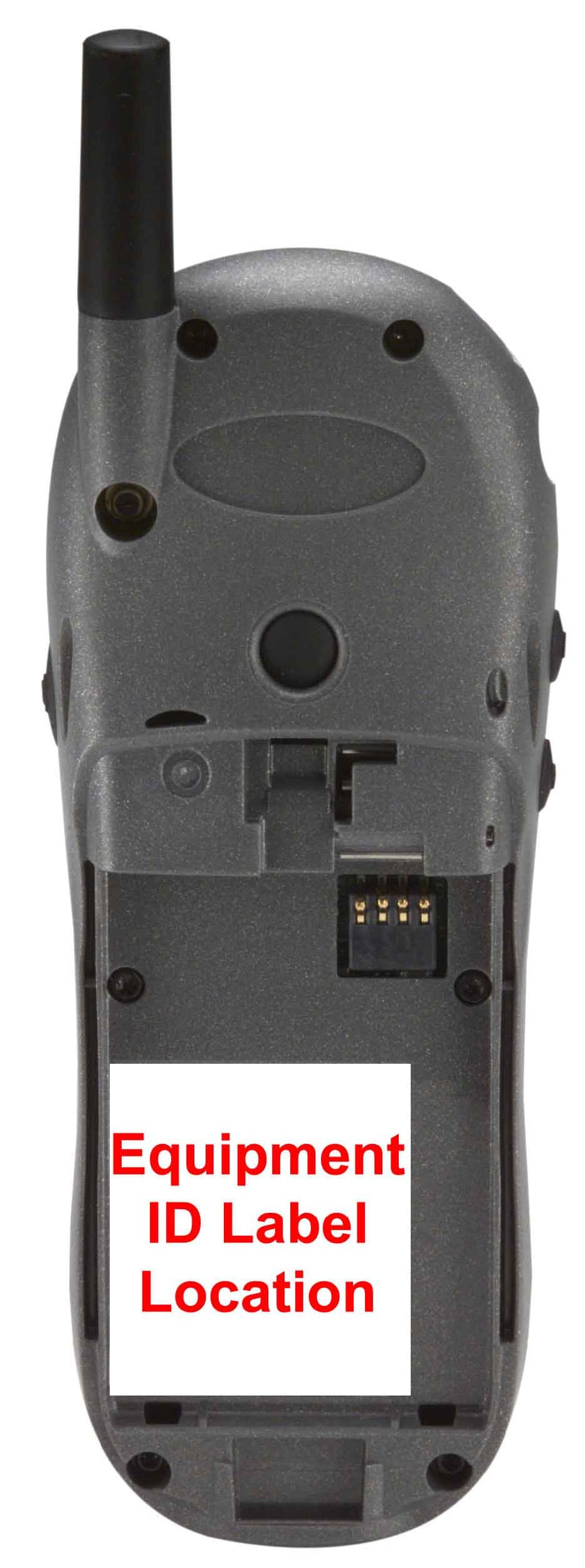
Click to zoom
Application Details
- Equipment Class
- TNE - Licensed Non-Broadcast Transmitter Held to Ear
- Date of Grant
- Feb 01, 2001
- Application Purpose
- Original Equipment
- Date of Application
- Jan 17, 2001
- Equipment Note
- Portable Cellular Transceiver
- Frequency Range
- 1851.25000000 - 1908.75000000
- Company
- Motorola Mobility LLC
- Country
- United States
Documents & Files
Document Text
Text extracted from the exhibit documents filed with the FCC. Open a document above to read the original.
Users Manual
APPLICANT: MOTOROLA, INC.FCC ID: IHDT56AL1 EXHIBIT 8 INSTRUCTION MANUAL A revised preliminary draft copy of the Users Manual follows: CDMA Tarpon Wireless Telephone Basic User’s Guide Preliminary Draft June 19, 2000 i Contents Contents Safety Information . . . . . . . . . . . . . . . . . . . . . . . . . . . . . . . . . . 3 Getting Started . . . . . . . . . . . . . . . . . . . . . . . . . . . . . . . . . . . . . 10 Opening the Box . . . . . . . . . . . . . . . . . . . . . . . . . . . . . . . . . . . . 10 Battery . . . . . . . . . . . . . . . . . . . . . . . . . . . . . . . . . . . . . . . . . . . . 11 Turning On Your Phone . . . . . . . . . . . . . . . . . . . . . . . . . . . . . . 12 Placing a Call . . . . . . . . . . . . . . . . . . . . . . . . . . . . . . . . . . . . . . 13 Ending a Call . . . . . . . . . . . . . . . . . . . . . . . . . . . . . . . . . . . . . . 14 Redialing a Number . . . . . . . . . . . . . . . . . . . . . . . . . . . . . . . . . 14 Receiving a Call . . . . . . . . . . . . . . . . . . . . . . . . . . . . . . . . . . . . 14 Viewing Your Phone Number . . . . . . . . . . . . . . . . . . . . . . . . . . 14 Learning More Tasks . . . . . . . . . . . . . . . . . . . . . . . . . . . . . . . 15 Navigating to Features . . . . . . . . . . . . . . . . . . . . . . . . . . . . . . . 15 Using Menu Features . . . . . . . . . . . . . . . . . . . . . . . . . . . . . . . . 19 Entering Text . . . . . . . . . . . . . . . . . . . . . . . . . . . . . . . . . . . . . . 22 Storing an Entry in the Phonebook . . . . . . . . . . . . . . . . . . . . . 25 Using Text Messages . . . . . . . . . . . . . . . . . . . . . . . . . . . . . . . . . 29 Using Voicemail . . . . . . . . . . . . . . . . . . . . . . . . . . . . . . . . . . . . 32 Locking and Unlocking Your Phone . . . . . . . . . . . . . . . . . . . . 33 Caller ID . . . . . . . . . . . . . . . . . . . . . . . . . . . . . . . . . . . . . . . . . . 35 Automatic Redial . . . . . . . . . . . . . . . . . . . . . . . . . . . . . . . . . . . 35 Call Waiting . . . . . . . . . . . . . . . . . . . . . . . . . . . . . . . . . . . . . . . 36 Unanswered Calls . . . . . . . . . . . . . . . . . . . . . . . . . . . . . . . . . . . 36 Dialing Emergency Numbers . . . . . . . . . . . . . . . . . . . . . . . . . 37 Additional Dialing Features . . . . . . . . . . . . . . . . . . . . . . . . . . . 37 Contents ii Using In-Call Features . . . . . . . . . . . . . . . . . . . . . . . . . . . . . . . 39 Phone Fundamentals . . . . . . . . . . . . . . . . . . . . . . . . . . . . . . . 40 Phone Diagram . . . . . . . . . . . . . . . . . . . . . . . . . . . . . . . . . . . . 40 Display . . . . . . . . . . . . . . . . . . . . . . . . . . . . . . . . . . . . . . . . . . . 41 Status Light . . . . . . . . . . . . . . . . . . . . . . . . . . . . . . . . . . . . . . . 43 Volume Keys . . . . . . . . . . . . . . . . . . . . . . . . . . . . . . . . . . . . . . . 44 Battery Use . . . . . . . . . . . . . . . . . . . . . . . . . . . . . . . . . . . . . . . . 44 When You’re Ready to Do More . . . . . . . . . . . . . . . . . . . . 46 Menu Map . . . . . . . . . . . . . . . . . . . . . . . . . . . . . . . . . . . . . . . . 46 Menu Feature Descriptions . . . . . . . . . . . . . . . . . . . . . . . . . . . 47 Conference Call . . . . . . . . . . . . . . . . . . . . . . . . . . . . . . . . . . . . 54 VoiceNotes . . . . . . . . . . . . . . . . . . . . . . . . . . . . . . . . . . . . . . . . . 55 Datebook . . . . . . . . . . . . . . . . . . . . . . . . . . . . . . . . . . . . . . . . . . 59 Configuring Settings . . . . . . . . . . . . . . . . . . . . . . . . . . . . . . . . 62 FDA Update . . . . . . . . . . . . . . . . . . . . . . . . . . . . . . . . . . . . . . . . 74 Index . . . . . . . . . . . . . . . . . . . . . . . . . . . . . . . . . . . . . . . . . . . . . . 84 Patent Information . . . . . . . . . . . . . . . . . . . . . . . . . . . . . . . . . 91 3 Safety Information Safety Information Important: Read this information before using your wireless handheld phone. Exposure to Radio Frequency Signals Your wireless handheld portable telephone is a low power radio transmitter and receiver. When it is ON, it receives and also sends out radio frequency (RF) signals. In August 1996, The Federal Communications Commission (FCC) adopted RF exposure guidelines with safety levels for handheld wireless phones. Those guidelines are consistent with safety standards previously set by both U.S. and international standards bodies: • American National Standards Institute (ANSI) IEEE. C95. 1-1992 • National Council on Radiation Protection and Measurement (NCRP). Report 86 • International Commission on Non-Ionizing Radiation Protection (ICNIRP) 1996 • Ministry of Health (Canada), Safety Code 6 Those standards were based on comprehensive and periodic evaluations of the relevant scientific literature. For example, over 120 scientists, engineers, and physicians from universities, Safety Information 4 government health agencies, and industry reviewed the available body of research to develop the ANSI Standard (C95.1). The design of your phone complies with the FCC guidelines (and those standards). For additional information concerning exposure to radio frequency signals, see the statement by the FDA at the end of this user guide. To maintain compliance with FCC RF exposure guidelines, if you wear a handset on your body, use the Motorola-supplied or approved carrying case, holster, or other body-worn accessory. If you do not use a body-worn accessory, ensure the antenna is at least one inch (2.5 centimeters) from your body when transmitting. Use of non-Motorola accessories may violate FCC RF exposure guidelines. Antenna Care Use only the supplied or an approved replacement antenna. Unauthorized antennas, modifications, or attachments could damage the phone and may violate FCC regulations. Phone Operation Normal Operation Hold the phone as you would any other telephone, with the antenna pointed up and over your shoulde…
Text truncated - open the document above for the full version.
Users Manual
21 Getting Started What’s in the Box? Your digital wireless phone typically comes equipped with a battery and a charger. Other accessory options can customize your phone for maximum performance and portability. The following illustrations show a sample of the package contents. Note: Your phone and accessories may not look exactly as pictured. Motorola Telephone Belt Clip Battery
Attestation Statements
APPLICANT: MOTOROLA, INC.FCC ID : IHDT56AL1 Exhibit 2A SPECIFICATION COMPLIANCE STATEMENT Engineer-in-Charge Equipment Authorization Branch Federal Communications Commission We hereby certify that this transmit and receive equipment (FCC ID: IHDT56AL1) for trimode, dual band mobile station cellular use id capable of compliance with the TIA/EIA-95-B Mobile Station-Base Station Compatibility Standards for Dual-Mode Spread Spectrum Systems, December 1998. (Signed – Peck Minsok) Peck Minsok Engineering Section Manager Cellular Subscriber Equipment (Signed – S.T,Liew ) S.T.Liew Engineering Manager Cellular Subscriber Equipment APPLICANT: MOTOROLA, INC.FCC ID : IHDT56AL1 Exhibit 2B STATEMENT OF CERTIFICATION The technical data supplied with this application, having been taken under my supervision is hereby duly certified. The following is a statement of my qualifications: PH,D : 1993 Arizona state university at Tempe, AZ MSEE: 1987 Ohio university at Athens, Ohio BSEE: 1981 Hanyang university at Seoul, Korea 12 years cellular Design Experience SIGNATURE: () Peck Minsok NAME: Peck Minsok DATE: January 12, 2001 POSITION: Engineering Manager I hereby certify that the above application was prepared under my direction and that to the best of my knowledge and belief, the facts set forth in the application and accompanying technical data are true and correct. SIGNATURE: ( ) S.T,Liew NAME: S.T,Liew DATE: January 12, 2001 POSITION: Engineering Manager
Cover Letter(s)
APPLICANT: MOTOROLAFCC ID: IHDT56AL1 Exhibit 13 January 17, 2001 CONFIDENTIALITY REQUEST CONTAINED WITHIN Federal Communications Commission Authorization and Evaluation Division 7435 Oakland Mills Road Columbia, Maryland 21046 Re: Application for Cellular/PCS Transceiver Certification Gentlemen: Application: Motorola, Inc., Personal Communications Sector, 600 N. U.S. Highway 45, Libertyville, Illinois 60048-1286 herein submits: Application for Equipment Authorization (FCC Form 731-October 1992 with integrated Fee Processing Form, Fee Codes EFT and EBC), application fee in the amount of $640, and Exhibits; for Certification of a Cellular Transceiver, FCC ID: IHDT56AL1. Motorola is also the manufacturer of this equipment. Confidentiality: Pursuant to Section 0.459 of the Commission's rules (CFR 47), Motorola requests confidentiality for portions of the material contained in this application and that the identified material be withheld from public inspection following the grant of this authorization. This material contains Motorola's trade secrets and confidential information that Motorola does not customarily release to the public and which is otherwise not generally available to the public. Confidentiality is requested for the following exhibits: • Exhibit 4 Block Diagrams • Exhibit 5 Schematics • Exhibit 12 Operational Description Description: This equipment has the capability to operate in the conventional Analog Cellular standard in the 800 MHz cellular band, and the Digital CDMA standard in both the 800 MHz and the PCS bands, as outlined in EIA/TIA IS-95-A "Mobile Station – Base Station Compatibility Standard for Dual-Mode Wideband Spread Spectrum Cellular System”. Technical details for this alternate cellular technology (permitted under the cellular service option provisions in Section 22.933 of the Commission's rules) related to Type Acceptance of this equipment, as noted in paragraphs 31 and 32 of the Report and Order in FCC GEN. Docket No. 87- 390, are detailed in Exhibit 12. Contact Information: Please contact me by telephone at (847) 523-6167,or by e-mail ([email protected]), if there are questions or additional information needed concerning this filing. Regards, Andrew J. Bachler FCC Liaison Cellular Subscriber Sector 600 N. U.S. Highway 45 Libertyville, IL 60048-5343
External Photos
APPLICANT: MOTOROLA, INC. FCC ID: IHDT56AL1 EXHIBIT 3 Front View Rear View, with Battery Removed to Show Equipment ID Label
ID Label/Location Info
APPLICANT: MOTOROLA, INC. FCC ID: IHDT56AL1 EXHIBIT 1 FCC IDENTIFICATION (NAMEPLATE) INFORMATION . The FCC label shown is representative of the label that will appear on the radio when in production. It will be Placed on the radio telephone as shown in Exhibit 3. Other information may also be included on this label. FCC ID: IHDT56AL1
Internal Photos
APPLICANT: MOTOROLA, INC. FCC ID: IHDT56AL1 EXHIBIT 9 Front View (Shields Removed) Rear View (Shields Removed)
Parts List/Tune Up Info
APPLICANT: MOTOROLA INC.FCC ID: IHDT56AL1 EXHIBIT 10 TRANSCEIVER ADJUSTMENTS/TUNE-UP PROCEDURE There are no user adjustments or tuning in this mobile cellular transceiver.
RF Exposure Info
APPLICANT: MOTOROLA, INC. FCC ID: IHDT56AL1 E E x x h h i i b b i i t t 1 1 1 1 P P a a g g e e 1 1 Exhibit 11: SAR Test Report: IHDT56AL1 Date of test: 12/28/00-1/11/01 Laboratory: Motorola Personal Communications Sector Product Safety Laboratory 2001 N. Division Room: AS228 Harvard, Illinois 60033 Test Responsible: Steven Hauswirth Staff Engineer Accreditation: ISO Guide 25 Accredited Lab, A2LA certificate #1651-01 Statement of Compliance: Motorola declares under its sole responsibility that portable cellular telephone FCC ID IHDT56AL1 to which this declaration relates, is in conformity with the appropriate RF exposure standards, recommendations and guidelines. It also declares that the product was tested in accordance with the appropriate measurement standards, guidelines and recommended practices. Any deviations from these standards, guidelines and recommended practices are noted below: ©Motorola This test report shall not be reproduced in full, without written approval of the laboratory. The results and statements contained herein relate only to the items tested. The names of individuals involved may be mentioned only in connection with the statements or results from this report. Motorola encourages all feedback, both positive and negative, on this test report. APPLICANT: MOTOROLA, INC. FCC ID: IHDT56AL1 E E x x h h i i b b i i t t 1 1 1 1 P P a a g g e e 2 2 Table of Contents 1) Introduction 3 2) Description of the Device Under Test 3 Antenna description 3 Device description 3 3) Test Results 3 4) Test Equipment 4 4.1 Dosimetric system 4 4.2 Additional equipment used 5 5) Electrical parameters of the tissue simulating liquid 5 6) System Accuracy Verification 5 Reference Notes Appendix 1: SAR distribution comparison for the system accuracy verification 7 Appendix 2: SAR distribution plots for Phantom Head Adjacent Use 8 Appendix 3: SAR distribution plots for Body Worn Configuration 10 Appendix 4: Photographs of the device under test 11 APPLICANT: MOTOROLA, INC. FCC ID: IHDT56AL1 E E x x h h i i b b i i t t 1 1 1 1 P P a a g g e e 3 3 1. Introduction The Motorola Personal Communications Sector Product Safety Laboratory has performed measurements of the maximum potential exposure to the user of portable cellular phone FCC ID IHDT56AL1. The Specific Absorption Rate (SAR) of this product was measured. The portable cellular phone was tested in accordance with the latest available test guidelines. The SAR values found for the portable cellular phone (FCC ID IHDT56AL1) are below the maximum recommended levels of 1.6 W/kg. Detailed procedures of the test are described in the Motorola Exhibit 11 Reference SAR Test Report. 2. Description of the Device Under Test Antenna description Type Extendable whip Location Right Side Configuration Helix Device description FCC ID Number IHDT56AL1 Serial number A88BC505 Mode(s) of Operation AMPS800 CDMA800 CDMA1900 Modulation Mode(s) AMPS CDMA CDMA Maximum Output Power Setting 26.4dBm 23.6dBm 23.9dBm Duty Cycle 1:1 1:1 1:1 Transmitting Frequency Rang(s) 824-849MHz 824-849MHz 1851-1909MHz 3. Test Results The SAR results shown in tables 1 and 2 are maximum SAR values averaged over 1 gram of phantom tissue. Also shown are the measured conducted output powers and the temperature of the test facility during the test. The test sample was operated in a test mode that allows control of the transmitter without the need to place actual phone calls. For the purposes of this test the unit is commanded to test mode and manually set to the proper channel, transmitter power level and transmit mode of operation. The phone was then placed in the SAR measurement system with a fully charged battery. A full data set output of two test conditions with the highest SAR values from the Dasy measurement system is included as appendix 2 and 3. The test conditions included are indicated as bold numbers in the following table. All other test conditions measured lower SAR values than those included. Note that digital mode SAR data was measured only for the test conditions that resulted in the highest analog SAR values. This is because the only difference between analog and digital modes that can impact SAR is the average transmitter power. APPLICANT: MOTOROLA, INC. FCC ID: IHDT56AL1 E E x x h h i i b b i i t t 1 1 1 1 P P a a g g e e 4 4 SAR, 1g (W/kg) f Left Head Right Head (MHz) Description Conducted Output Power (dBm) Ant Ext Ant Ret Ant Ext Ant Ret Channel 991 25.6 1.27 0.92 1.00 0.82 Channel 384 26.7 0.97 1.04 1.12 1.09 Analog 800MHz Channel 799 26.4 1.16 1.26 1.12 1.12 Channel 1013 23.2 0.63 Digital 800MHz Channel 779 23.6 0.77 Channel 25 23.9 0.57 1.38 0.27 1.32 Channel 600 23.3 0.63 0.98 0.30 0.79 Digital 1900MH z Channel 1175 22.9 0.23 0.60 0.17 0.63 Table 1: SAR measurement results for the portable cellular telephone FCC ID IHDT56AL1 at highest possible output power. Measured against the head. SAR, 1g (W/kg) f Belt Clip (MHz) Description Conducted Output Power (dBm) Ant Ext Ant Ret Channel 991 25.6 1.36 0.95 Channel 384 26.7 0.64 0.79 Analog 800MHz Channel 799 26.4 0.63 0.67 Digital 800MHz Channel 1013 23.2 0.79 0.66 Channel 25 23.9 0.75 0.54 Channel 600 23.3 0.78 0.39 Digital 1900MHz Channel 1175 22.9 0.36 0.22 Table 2: SAR measurement results for the portable cellular telephone FCC ID IHDT56AL1 at highest possible output power. Measured against the body. 4. Test Equipment Used 4.1 Dosimetric System The Motorola Personal Communications Sector Product Safety Laboratory utilizes a Dosimetric Assessment System (Dasy3™) SAR measurement system manufactured by Schmid & Partner Engineering AG (SPEAG™), of Zurich Switzerland. The overall RSS uncertainty of the measurement system is ±12.0% (K=1). Description Serial Number Cal Due Date DASY3 DAE V1 SN375 10/2001 E-Field Probe ETDV6 SN1515 2/2001 Dipole Validation Kit, DV835V2 SN416 2/2002 Dipole Validation Kit, DV1800V2 SN259 1/2002 APPLICANT: MOTOROLA, INC. FCC ID: IHDT56AL1 E E x x h h i i b b i i t t 1 1 1 1 P P a a g g e e 5 5 4…
Text truncated - open the document above for the full version.
RF Exposure Info
APPLICANT: MOTOROLA, INC. FCC ID: IHDT56AL1 E E x x h h i i b b i i t t 1 1 1 1 P P a a g g e e 1 1 Exhibit 11: SAR Test Report: IHDT56AL1 Date of test: 12/28/00-1/11/01 Laboratory: Motorola Personal Communications Sector Product Safety Laboratory 2001 N. Division Room: AS228 Harvard, Illinois 60033 Test Responsible: Steven Hauswirth Staff Engineer Accreditation: ISO Guide 25 Accredited Lab, A2LA certificate #1651-01 Statement of Compliance: Motorola declares under its sole responsibility that portable cellular telephone FCC ID IHDT56AL1 to which this declaration relates, is in conformity with the appropriate RF exposure standards, recommendations and guidelines. It also declares that the product was tested in accordance with the appropriate measurement standards, guidelines and recommended practices. Any deviations from these standards, guidelines and recommended practices are noted below: ©Motorola This test report shall not be reproduced in full, without written approval of the laboratory. The results and statements contained herein relate only to the items tested. The names of individuals involved may be mentioned only in connection with the statements or results from this report. Motorola encourages all feedback, both positive and negative, on this test report. APPLICANT: MOTOROLA, INC. FCC ID: IHDT56AL1 E E x x h h i i b b i i t t 1 1 1 1 P P a a g g e e 2 2 Table of Contents 1) Introduction 3 2) Description of the Device Under Test 3 Antenna description 3 Device description 3 3) Test Results 3 4) Test Equipment 4 4.1 Dosimetric system 4 4.2 Additional equipment used 5 5) Electrical parameters of the tissue simulating liquid 5 6) System Accuracy Verification 5 Reference Notes Appendix 1: SAR distribution comparison for the system accuracy verification 7 Appendix 2: SAR distribution plots for Phantom Head Adjacent Use 8 Appendix 3: SAR distribution plots for Body Worn Configuration 10 Appendix 4: Photographs of the device under test 11 APPLICANT: MOTOROLA, INC. FCC ID: IHDT56AL1 E E x x h h i i b b i i t t 1 1 1 1 P P a a g g e e 3 3 1. Introduction The Motorola Personal Communications Sector Product Safety Laboratory has performed measurements of the maximum potential exposure to the user of portable cellular phone FCC ID IHDT56AL1. The Specific Absorption Rate (SAR) of this product was measured. The portable cellular phone was tested in accordance with the latest available test guidelines. The SAR values found for the portable cellular phone (FCC ID IHDT56AL1) are below the maximum recommended levels of 1.6 W/kg. Detailed procedures of the test are described in the Motorola Exhibit 11 Reference SAR Test Report. 2. Description of the Device Under Test Antenna description Type Extendable whip Location Right Side Configuration Helix Device description FCC ID Number IHDT56AL1 Serial number A88BC505 Mode(s) of Operation AMPS800 CDMA800 CDMA1900 Modulation Mode(s) AMPS CDMA CDMA Maximum Output Power Setting 26.4dBm 23.6dBm 23.9dBm Duty Cycle 1:1 1:1 1:1 Transmitting Frequency Rang(s) 824-849MHz 824-849MHz 1851-1909MHz 3. Test Results The SAR results shown in tables 1 and 2 are maximum SAR values averaged over 1 gram of phantom tissue. Also shown are the measured conducted output powers and the temperature of the test facility during the test. The test sample was operated in a test mode that allows control of the transmitter without the need to place actual phone calls. For the purposes of this test the unit is commanded to test mode and manually set to the proper channel, transmitter power level and transmit mode of operation. The phone was then placed in the SAR measurement system with a fully charged battery. A full data set output of two test conditions with the highest SAR values from the Dasy measurement system is included as appendix 2 and 3. The test conditions included are indicated as bold numbers in the following table. All other test conditions measured lower SAR values than those included. Note that digital mode SAR data was measured only for the test conditions that resulted in the highest analog SAR values. This is because the only difference between analog and digital modes that can impact SAR is the average transmitter power. APPLICANT: MOTOROLA, INC. FCC ID: IHDT56AL1 E E x x h h i i b b i i t t 1 1 1 1 P P a a g g e e 4 4 SAR, 1g (W/kg) f Left Head Right Head (MHz) Description Conducted Output Power (dBm) Ant Ext Ant Ret Ant Ext Ant Ret Channel 991 25.6 1.27 0.92 1.00 0.82 Channel 384 26.7 0.97 1.04 1.12 1.09 Analog 800MHz Channel 799 26.4 1.16 1.26 1.12 1.12 Channel 1013 23.2 0.63 Digital 800MHz Channel 779 23.6 0.77 Channel 25 23.9 0.57 1.38 0.27 1.32 Channel 600 23.3 0.63 0.98 0.30 0.79 Digital 1900MH z Channel 1175 22.9 0.23 0.60 0.17 0.63 Table 1: SAR measurement results for the portable cellular telephone FCC ID IHDT56AL1 at highest possible output power. Measured against the head. SAR, 1g (W/kg) f Belt Clip (MHz) Description Conducted Output Power (dBm) Ant Ext Ant Ret Channel 991 25.6 1.36 0.95 Channel 384 26.7 0.64 0.79 Analog 800MHz Channel 799 26.4 0.63 0.67 Digital 800MHz Channel 1013 23.2 0.79 0.66 Channel 25 23.9 0.75 0.54 Channel 600 23.3 0.78 0.39 Digital 1900MHz Channel 1175 22.9 0.36 0.22 Table 2: SAR measurement results for the portable cellular telephone FCC ID IHDT56AL1 at highest possible output power. Measured against the body. 4. Test Equipment Used 4.1 Dosimetric System The Motorola Personal Communications Sector Product Safety Laboratory utilizes a Dosimetric Assessment System (Dasy3™) SAR measurement system manufactured by Schmid & Partner Engineering AG (SPEAG™), of Zurich Switzerland. The overall RSS uncertainty of the measurement system is ±12.0% (K=1). Description Serial Number Cal Due Date DASY3 DAE V1 SN375 10/2001 E-Field Probe ETDV6 SN1515 2/2001 Dipole Validation Kit, DV835V2 SN416 2/2002 Dipole Validation Kit, DV1800V2 SN259 1/2002 APPLICANT: MOTOROLA, INC. FCC ID: IHDT56AL1 E E x x h h i i b b i i t t 1 1 1 1 P P a a g g e e 5 5 4…
Text truncated - open the document above for the full version.
RF Exposure Info
January 30, 2001 Supplement to SAR Test Report for Motorola portable cellular phone (FCC ID IHDT56AL1). Prepared by: Steven Hauswirth, Staff Engineer Motorola Personal Communications Sector Product Safety Laboratory Libertyville, Illinois Contents 1) Summary of FCC request for additional information 2) Peak SAR locations for the body-worn SAR configurations 1. Summary of FCC request for additional information There was a request for additional information regarding Motorola’s SAR Test Report for Motorola portable cellular phone (FCC ID IHDT56AL1) dated January 11, 2001. The requested information may be summarized as follows: Please identify the peak SAR locations for the body-worn SAR configurations. Note: PCS mode has different peak locations for antenna IN and OUT. 2. Peak SAR locations for the body-worn SAR configurations The location of peak SAR when the phone is in the supplied belt-clip for PCS band is shown in figures 1 – 4. Figure 1. Body-worn 800MHz contour plot overlaid on the back of the phone with Antenna Extended Figure 2. Body-worn 800MHz contour plot overlaid on the back of the phone with Antenna Retracted Figure 3. Body-worn 1900MHz contour plot overlaid on the back of the phone with Antenna Extended Figure 4. Body-worn 1900MHz contour plot overlaid on the back of the phone with Antenna Retracted
Test Report
APPLICANT: MOTOROLA, INC.FCC ID : IHDT56AA1 EXHIBIT 6 SUBMITTED MEASURED DATA INDEX RF Power Output...............................................................................................6A Audio Frequency Response...............................................................................6B Post Limiter Low Pass Filter Response - Graph................................................6C Signaling Channel Audio Roll-Off Filter Response - Graph...............................6D Modulation Limiting (Compandor In) - Graph.....................................................6E1 Modulation Limiting (Compandor Out) - Graph..................................................6E2 Occupied Bandwidth, Audio - Photograph.........................................................6F1 Occupied Bandwidth, Audio and SAT - Graph...................................................6F2 Occupied Bandwidth, Wideband Data - Graph..................................................6F3 Occupied Bandwidth, Signaling Tone and SAT - Graph....................................6F4 Occupied Bandwidth, Digital - Graph.................................................................6F5 Analog Conducted Spurious and Harmonic Emissions - Graph........................6G1 Digital Conducted Spurious and Harmonic Emissions, 800 MHz - Graph.........6G2 Digital Conducted Spurious and Harmonic Emissions, 1900 MHz- Graph........6G3 Analog Radiated Spurious and Harmonic Emissions - Graph...........................6H1 Digital Radiated Spurious and Harmonic Emissions, 800 MHz - Graph............6H2 Digital Radiated Spurious and Harmonic Emissions, 1900 MHz - Graph..........6H3 Receiver Radiated Spurious and Harmonic Emissions, Analog........................6J1 Receiver Radiated Spurious and Harmonic Emissions, 800 MHz Digital..........6J2 Receiver Radiated Spurious and Harmonic Emissions, 1900 MHz...................6J3 Analog Frequency Change vs. Temperature.....................................................6K1 Digital Frequency Change vs. Temperature, 800 MHz......................................6K2 Digital Frequency Change vs. Temperature, 1900 MHz....................................6K Analog Frequency Change vs. Supply Voltage.................................................6L1 Digital Frequency Change vs. Supply Voltage, 800 MHz..................................6L2 Digital Frequency Change vs. Supply Voltage, 1900 MHz................................6L3 Measurement Techniques..................................................................................6M APPLICANT: MOTOROLA, INC.FCC ID : IHDT56AL1 EXHIBIT 6A RF POWER OUTPUT DATA The input supply to the transmitter was set at 3.6 Volts. The RF power output was measured with the indicated voltage and current applied into the ANT port via 50ohm cable. ANALOG MODE Measured RF output: 0.437W Measured DC voltage: 3.6V Measured DC current: 725mA Measured RF input: 3mW 800 Mhz Digital CDMA In Digital Mode the values measured for RF Output, DC Current and RF Input Power are all average values which reflect a 100% transmit duty cycle in CDMA operation. Measured RF output: 0.230W Measured DC voltage: 3.6V Measured DC current: 615mA. Measured RF input: 0.5mW 1900 Mhz Digital CDMA In Digital Mode the values measured for RF Output, DC Current and RF Input Power are all average values which reflect a 100% transmit duty cycle in CDMA operation. Measured RF output: 0.245W Measured DC voltage: 3.6V Measured DC current: 625mA. Measured RF input: 0.5mW EFFECTIVE RADIATED POWER Since the unit is intended for use with a provided antenna (and “non standard” RF connector), ERP is measured. The dipole antenna substitution method was used. The result indicated is the maximum ERP found over the channels and radio orientations tested. Maximum Effective Radiated Power: Analog Mode: 25.94 dBm ( 0.393W) Maximum Effective Radiated Power: 800 Digital CDMA Mode: 21.7 dBm ( 0.148 W) Maximum Effective Isotropic Radiated Power: 1900 Digital CDMA Mode: 25.1 dBm (0.325 W) APPLICANT: MOTOROLA, INC.FCC ID : IHDT56AL1 EXHIBIT 6B Audio Frequency Response -35 -30 -25 -20 -15 -10 -5 0 5 10 15 100100010000100000 Frequency(Hz) Modulation(dB) Wide Modulation (dB)USLLSL APPLICANT: MOTOROLA, INC.FCC ID : IHDT56AL1 EXHIBIT 6C Post Limiter Low Pass Filter Response Graph APPLICANT: MOTOROLA, INC.FCC ID : IHDT56AL1 EXHIBIT 6D Signaling Channel Audio Roll-Off Filter Response Graph APPLICANT: MOTOROLA, INC.FCC ID : IHDT56AL1 EXHIBIT 6E1 Modulation Limiting (Compander In) Frequency Deviation characteristic 0 2 4 6 8 10 12 -50-48-46-44-42-40-38-36-34-32-30-28-26-24-22-20-18-16-14-12-10-8-6-4-202468101214161820 Audio Level (dB) Deviation(Hz) 300Hz 1KHz 3KHz APPLICANT: MOTOROLA, INC.FCC ID : IHDT56AL1 EXHIBIT 6E2 Modulation Limiting (Compander out) Frequency Deviation characteristic 0 2 4 6 8 10 12 -50-48-46-44-42-40-38-36-34-32-30-28-26-24-22-20-18-16-14-12-10-8-6-4-202468101214161820 Audio Level (dB) Deviation(Hz) 300Hz 1KHz 3KHz APPLICANT: MOTOROLA, INC.FCC ID : IHDT56AL1 EXHIBIT 6F1 BANDWIDTH MEASUREMENT DATA FOR TRANSMITTER TYPES F8W DEVIATION OF THE CARRIER WITH 2500 Hz. AUDIO MODULATION HORIZONTAL SCALE = 20 kHz / DIVISION VERTICAL SCALE = 10 dB / DIVISION (REFERENCE LEVEL = 30.5 dBm) RESOLUTION BANDWIDTH =1000 Hz VIDEO BANDWIDTH =1000 Hz AUDIO LEVEL = 16 dB GREATER THAN LEVEL REQUIRED TO PRODUCE + / - 6 kHz POWER LEVEL = 0.454W MEASURED DATA: 1. Instantaneous Deviation Control set for a maximum of +/- 12 kHz 2. Tune and adjust to obtain unmodulated carrier on the spectrum analyzer. Save trace of the unmodulated carrier. 3. Modulate the transmitter with the 2500 Hz. Tone, 16 dB greater than that required to produce +/- 6 kHz modulation. Photograph the sideband display while it is superimposed upon…
Text truncated - open the document above for the full version.
Contact Information
Applicant
Jeff Narducci(Director Product Compliance)
Technical Specifications
| # | Rule Parts | Frequency Range | Power Output | Emission | Tolerance |
|---|---|---|---|---|---|
| 4 | 22.901(d) | 1.85 GHz - 1.91 GHz | 320.00 mW | 1M25F9W | 150 Hz |
Other Applications from Motorola Mobility LLC
IHDT56AW9
May 12, 2026Smart Watch
Equipment Class
NII - Unlicensed National Information Infrastructure TXIHDT56AW5
Apr 08, 2026Mobile Cellular Phone
Equipment Class
DTS - Digital Transmission SystemIHDT56AW6
Mar 18, 2026Smart Watch
Equipment Class
JBP - Part 15 Class B Computing Device PeripheralIHDT56AX4
Mar 17, 2026Mobile Cellular Phone
Equipment Class
PCE - PCS Licensed Transmitter held to earIHDT56AW3
Mar 03, 2026Mobile Cellular Phone
Equipment Class
6XD - 15E 6 GHz Low Power Indoor Client