IHDT56CP1In-Cabin Bluetooth Module
Motorola Mobility LLC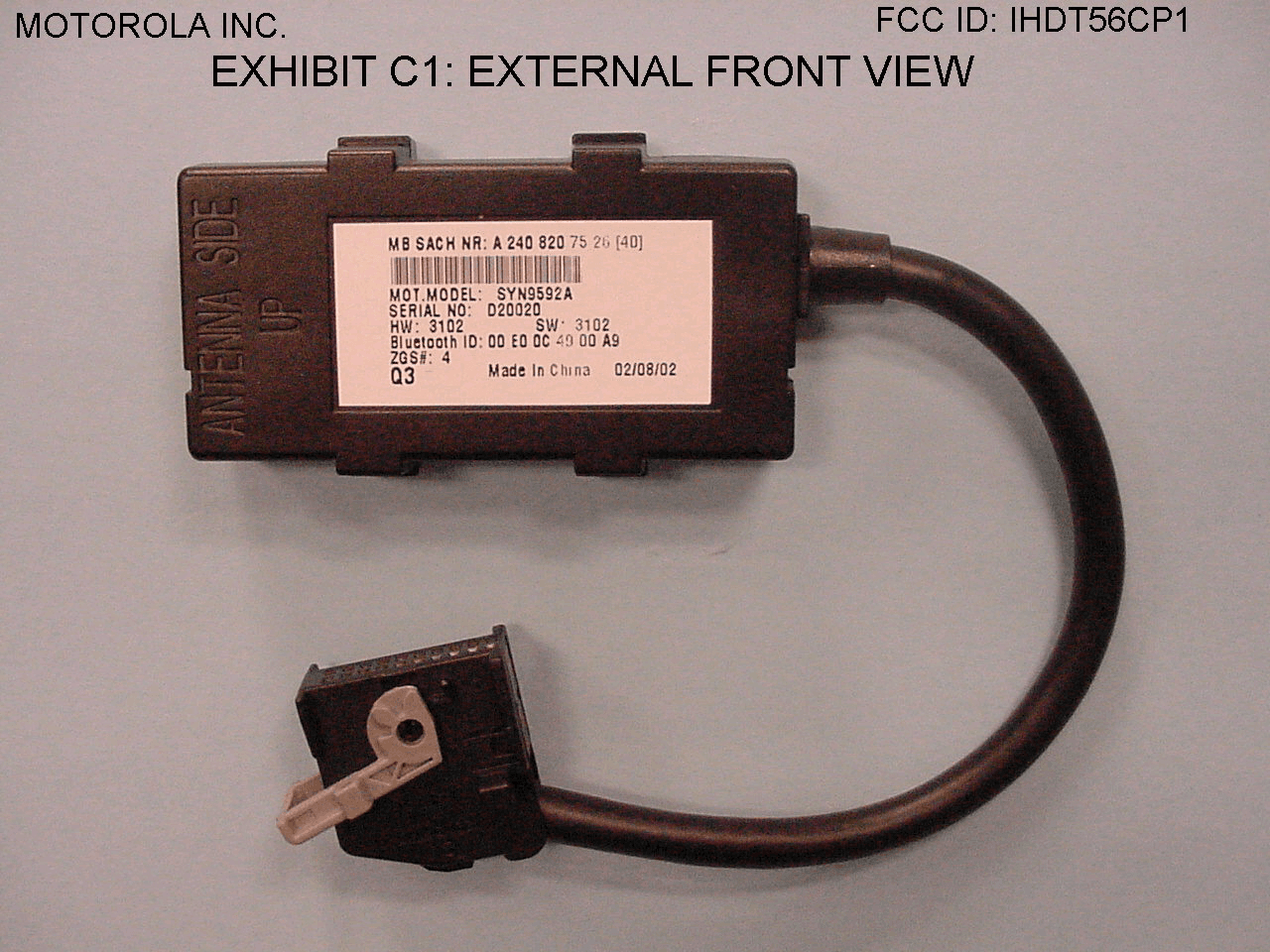
Click to zoom
Application Details
- Equipment Class
- DSS - Part 15 Spread Spectrum Transmitter
- Date of Grant
- Oct 13, 2002
- Application Purpose
- Original Equipment
- Date of Application
- Oct 13, 2002
- Equipment Note
- In-Cabin Bluetooth Module
- Frequency Range
- 2402.00000000 - 2480.00000000
- Company
- Motorola Mobility LLC
- Country
- United States
Documents & Files
Document Text
Text extracted from the exhibit documents filed with the FCC. Open a document above to read the original.
Users Manual
MOTOROLA INC FCC ID: IHDT56CP1 IN-CABIN BLUETOOTH MODULE INSTALLATION INSTRUCTIONS [Model# SYN9592A and cable length variants] 1. GENERAL: The In-Cabin Bluetooth Module facilitates a wireless Bluetooth interface between an in-vehicle control unit and other Bluetooth-enabled devices (such as a laptop PC, a handset, etc.). 2. ANTENNA AND MODULE INSTALLATION: The module utilizes an internal, pc board mounted, chip antenna. The unit is designed for installation within the passenger compartment of an automobile, usually in the center console area. The device should be mounted with a plastic bracket to minimize shadowing of the internal antenna. Due to the low power at which the unit transmits (0.0025 W max.), placement from an SAR perspective is not critical. All module installations are performed by the vehicle manufacturer. No end-user installation is involved. Any unauthorized changes or modifications not expressly approved by Motorola could void the user’s authority to operate this equipment. 3. I/O CONNECTION: A cable mounted 20-pin female automotive connector is utilized to provide power and vehicle bus communications. This connector will only mate with a corresponding connector in the vehicle’s prewire. 4. SPECIFICATIONS: ??Frequency range: 2402 MHz – 2480 MHz ??Operating current: 1.5A nominal ??Operating voltage: 13.2V nominal ??Operating temp. range: -30?C to +70?C ??Storage temp. range: -40?C to +85?C ??Output power: 0.0025 W max MOTOROLA INC FCC ID: IHDT56CP1 IN-CABIN BLUETOOTH MODULE USER MANUAL [Model# SYN9592A and cable length variants] 1. GENERAL: The In-Cabin Bluetooth Module facilitates a wireless Bluetooth interface between an in-vehicle control unit and other Bluetooth-enabled devices (such as a laptop PC, a handset, etc.). 2. ANTENNA AND MODULE INSTALLATION: The module utilizes an internal, pc board mounted, chip antenna. The unit is designed for installation within the passenger compartment of an automobile, usually in the center console area. The device should be mounted with a plastic bracket to minimize shadowing of the internal antenna. Due to the low power at which the unit transmits (0.0025 W max.), placement from an SAR perspective is not critical. All module installations are performed by the vehicle manufacturer. No end-user installation is involved. Any unauthorized changes or modifications not expressly approved by Motorola could void the user’s authority to operate this equipment. 3. I/O CONNECTION: A cable mounted 20-pin female automotive connector is utilized to provide power and vehicle bus communications. This connector will only mate with a corresponding connector in the vehicle’s prewire. 4. SPECIFICATIONS: ??Frequency range: 2402 MHz – 2480 MHz ??Operating current: 1.5A nominal ??Operating voltage: 13.2V nominal ??Operating temp. range: -30?C to +70?C ??Storage temp. range: -40?C to +85?C ??Output power: 0.0025 W max
Contact Information
Applicant
Jeff Narducci(Director Product Compliance)
Technical Contact
Motorola Inc.Gary L Christopher
[email protected]847 907-8375
50 Northwest Point Blvd. · Elk Grove Village, Illinois · United States
Non-Technical Contact
Motorola Inc.Eric S Kopfstein
Test Firm
Elite Electronic Engineering Co.Daniel Crowder
Technical Specifications
| # | Rule Parts | Frequency Range | Power Output |
|---|---|---|---|
| 1 | 15C | 2.40 GHz - 2.48 GHz | 930.00 µW |
Other Applications from Motorola Mobility LLC
IHDT56AW9
May 12, 2026Smart Watch
Equipment Class
NII - Unlicensed National Information Infrastructure TXIHDT56AW5
Apr 08, 2026Mobile Cellular Phone
Equipment Class
DTS - Digital Transmission SystemIHDT56AW6
Mar 18, 2026Smart Watch
Equipment Class
JBP - Part 15 Class B Computing Device PeripheralIHDT56AX4
Mar 17, 2026Mobile Cellular Phone
Equipment Class
PCE - PCS Licensed Transmitter held to earIHDT56AW3
Mar 03, 2026Mobile Cellular Phone
Equipment Class
6XD - 15E 6 GHz Low Power Indoor Client