IHDT56CX1Mobile Cellular CDMA Transceiver
Motorola Mobility LLC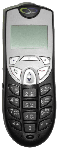
Click to zoom
Application Details
- Equipment Class
- TNB - Licensed Non-Broadcast Station Transmitter
- Date of Grant
- Jun 05, 2003
- Application Purpose
- Original Equipment
- Date of Application
- Jun 05, 2003
- Equipment Note
- Mobile Cellular CDMA Transceiver
- Frequency Range
- 824.70000000 - 848.31000000
- Company
- Motorola Mobility LLC
- Country
- United States
Documents & Files
Document Text
Text extracted from the exhibit documents filed with the FCC. Open a document above to read the original.
Users Manual
APPLICANT: MOTOROLA INC. FCC ID: IHDT56CX1 EXHIBIT 8 USERS MANUAL INFORMATION 1. A preliminary draft copy of the users manual follows: Note: This preliminary English version of the manual does not contain graphics. It is text only. The RF safety and antenna installation sections are on page 8. CMR2100 UM.doc1/78 MOTOROLA CMR 2100 – General View CMR2100 UM.doc2/78 Welcome! Thank you for choosing MOTOROLA / a global leader in communications technology. All MOTOROLA cellular phones are designed and manufactured to meet MOTOROLA's exacting specifications and world-class quality standards. The CMR 2100 is no exception to this rule. This car phone successfully passed reliability trials, such as temperature, humidity, vibration, dust, shaking, and dropping. With the CMR 2100 car phone you are guaranteed a superior product. Always at your service MOTOROLA CMR2100 UM.doc3/78 Contents Introduction What's new? Major advantages Safe and efficient operation The Basics General view Using the phone Using the smart button Reading the indicators Placing and ending calls Receiving calls Redialing numbers Basic tone controls Your phone and its shortcuts Using memory Making the most of memory Storing names and phone numbers Recalling from memory Scratch pad memory Advanced storage Using calling cards The menu Introducing the menu features The internal phonebook Recalling using the memory Phonebook status Editing a memory location Displaying the user's phone number Preference for name/number Call timers Viewing the individual timer Viewing the resettable timer Viewing the cumulative timer Resetting the timer One minute audible timer Programmable timers Tone controls Silent mode Selecting a ringer style Reminder tones setup Lock/security features Auto lock Secure options submenu Authentication – personal identification code Phone options Feature review Call options submenu Multi key answer Automatic answer CMR2100 UM.doc4/78 Instant redial Display options submenu Changing the language Changing the banner Backlighting Auto hyphen 24-hour clock Mini Browser options Launching the Mini Browser Power up mode Confirm at start-up System options submenu Displaying the system ID Using messaging Access to messages Caller IDs Caller ID options Voice mail options Reading your messages Using the Mini Browser Launching Mini Browser navigation Using bookmarks Using the Mini Browser Using data features Appendices Accompanying accessories Warranty CMR2100 UM.doc5/78 What's new? The CMR 2100 car phone is an innovative product incorporating the CDMA advanced digital technology, which offers the following new features: Mini Browser WAP The browser permits fast and easy access to personal information services* such as weather reports, sports results, traffic reports, etc. Expanded phonebook Your phone contains 99 memory locations, in each of which you can store up to 4 phone numbers. Data transmission support system Your phone supports a data transmission system*, using data transfer software such as Hyper Terminal, and a data cable. This feature permits data transmission and synchronization between your phone, a desktop computer and a laptop computer. Real time clock The digital CDMA system currently updates in real time the clock appearing in the display. Personal banner You can create your own message banner (up to 12 characters long) by using the Change Banner feature, which will be displayed by the phone when it is idle (see page __). Messages menu Viewing the call ID*, using voice mail messages*, and reading test messages* is very easy with the aid of the special messages key [**]. (see page __). * Contact your Service Provider for availability. Caller ID name If Caller ID* is active on your phone you will be able to see who is calling before you answer. The display will show your caller's name if it is in you phonebook. Large display screen Very wide alpha numeric LCD display, with 4 rows of text and 2 rows of menu indicators. The smart button Using the smart button you can do the following: • Operate the phone with one hand CMR2100 UM.doc6/78 • Store information • Recall a number, dial a number, end a call, etc. Updating the phonebook from a computer If the MOTOROLA data connecting kit* is installed in your car you can transfer names and phone numbers between your PC and the CMR 2100 (in both directions), using the Phone Synchronizer software. * Contact your Service Provider for availability. CMR2100 UM.doc7/78 Major features The CMR 2100, which is one of the most sophisticated cellular phones currently available, offers you a range of features suited to your life style. This sophisticated digital phone can help you to: • Redial automatically if the number if engaged • Receive a call discreetly through the earpiece • Dial easily and quickly using the Turbo Dial keys • Use browser services which provide fast access to personal information services • Connect to the data kit which provides options of sending data, etc. • Use the integral speakerphone kit • Recall phone numbers using the internal phonebook • Monitor length of calls using a range of call counters • Adjust the ringer style to the type you wish • Large, easy to use keypad in Hebrew and English • Large, easy-to-read display As you get to know the CMR 2100 you will discover more and more important and easy-to-use features. CMR2100 UM.doc8/78 Safety Information IMPORTANT: Read this information before using your wireless mobile phone. Exposure to Radio Frequency Signals Your wireless mobile telephone is a low power radio transmitter and receiver. When it is ON, it receives and also sends out radio frequency (RF) signals. International agencies have set standards and recommendations for the protection of public exposure to RF electromagnetic energy. • International Commission on Non-Ionizing Radiation Protection (ICNIRP)1996 • Verband Deutscher Elektrotechniker (VDE) DIN-0848 • United States Federal Communications Commission, Radio Frequency Exposure Guidelines (1996…
Text truncated - open the document above for the full version.
Attestation Statements
Applicant: Motorola, INC. FCC ID: IHDT56CX1 SPECIFICATION COMPLIANCE STATEMENT Engineer-in-Charge Equipment Authorization Branch Federal Communications Commission We hereby certify that this transmit and receive equipment (FCC ID: IHDT56CX1) for Vehicle fixed mobile cellular use is capable of compliance with TIA/EIA-95-B Mobile Station-Base Station Compatibility Standard for Dual-Mode Spread Spectrum Systems, December 1998. Yossi Lovton Engineering HW Manager N2CS – Next To Core Solution Yoram Zilberberg Engineering Manager N2CS – Next To Core Solution Exhibit 2 1 Applicant: Motorola, INC. FCC ID: IHDT56CX1 Exhibit 2 2 STATEMENT OF CERTIFICATION The technical data supplied with this application, having been taken under my Supervision is hereby duty certified. SIGNATURE: (signed) Yossi Lovton NAME: Yossi Lovton DATE: 03/24/03 POSITION: Engineering HW Manager I hereby certify that the above application was prepared under my direction and that to the best of my knowledge and belief, the facts set forth in the application and Accompanying technical data are true and correct: SIGNATURE: (signed) Yoram Zilberberg NAME: Yoram Zilberberg DATE: 03/24/03 POSITION: Engineering Manager
External Photos
APPLICANT: MOTOROLA, INC. FCC ID: IHDT56CX1 EXHIBIT 3 Front View Rear View
ID Label/Location Info
APPLICANT: MOTOROLA INC. FCC ID: IHDT56CX1 EXHIBIT 1 FCC IDENTIFICATION (NAMEPLATE) INFORMATION The FCC label shown is representative of the label that will appear on the radio when in production. It will be placed on the outside of the equipment as shown in Exhibit 3. Other information may also be included on this label. FCC ID: IHDT56CX1
Internal Photos
APPLICANT: MOTOROLA INC. FCC ID: IHDT56CX1 Rear View (Shields Removed) Front View (Shields Removed Exhibit 9 1 APPLICANT: MOTOROLA INC. FCC ID: IHDT56CX1 Rear View (With Shield) Front View (With Shield) Exhibit 9 2 APPLICANT: MOTOROLA INC. FCC ID: IHDT56CX1 Exhibit 9 3 Rear View with RF Module
Parts List/Tune Up Info
Applicant: Motorola, Inc. FCC ID: IHDT56CX1 Transceiver Adjustments/Tune-Up Procedure There are no user accessible adjustments or tuning in this fixed cellular transceiver. All necessary adjustments and tuning are performed during manufacturing of the product. Any adjustments or tuning after service or repair are done as part of that process as special equipment is required to perform such adjustments. Exhibit 10 1 Applicant: Motorola, Inc. FCC ID: IHDT56CX1 PART LIST Part Number Description FAF5021A ON GLASS ANTENNA FKN8103A SPIRIT POWER CABLE FTN6077A EXTERNAL MICROPHONE SSN4256A EXTERNAL SPEAKER FTN6215A SPIRIT Hang Up Holder FLN3107A SPIRIT Unit Assembly with Octopus cable FTN3106AA C18C TANAPA FCN6352A Spirit main board PART LIST OF FCN6352A (Spirit main board) Symbol P/N Description C102 2309369R41 CAP LYTIC 37 UF 20% 35 C103 2309369R41 CAP LYTIC 37 UF 20% 35 C106 2113743K16 CAP CHIP .220 UF +80-2 C107 2113743K16 CAP CHIP .220 UF +80-2 C108 2113928E01 CAP CER CHIP 1.0 UF 10 C111 2113743K15 CER CHIP CAP .100UF C112 2113743K15 CER CHIP CAP .100UF C113 2113741M69 CAP CHIP CLS2 100000PF C115 2113743M24 CAP CHIP 100000 PF +80 C116 2113928S04 CAP CER CHIP 0.100UF 1 C118 2113741M69 CAP CHIP CLS2 100000PF C122 2113928S04 CAP CER CHIP 0.100UF 1 C125 2113928S04 CAP CER CHIP 0.100UF 1 C126 2113743E20 CAP CHIP .10 UF 10% C127 2113743E20 CAP CHIP .10 UF 10% C131 2113743E20 CAP CHIP .10 UF 10% C134 2113928S04 CAP CER CHIP 0.100UF 1 C138 2113743E11 CAP CHIP .039 UF 10% X C139 2113743E11 CAP CHIP .039 UF 10% X C140 2113743N40 CAP CHIP 39.0 PF 5% CO C141 2113743A31 CAP CHIP 1.0 UF 10% X7 C149 2113741F25 CAP CHIP CL2 X7R REEL C150 2113741F25 CAP CHIP CL2 X7R REEL C151 2113743L17 CAP CHIP 1000 PF 10% X C152 2113743L17 CAP CHIP 1000 PF 10% X C153 2113743L17 CAP CHIP 1000 PF 10% X C154 2108607Y02 CAP. CERAMIC 4.7UF Y5V C155 2108607Y02 CAP. CERAMIC 4.7UF Y5V C156 2113741F25 CAP CHIP CL2 X7R REEL C158 2113944A40 CAP CER CHP 100.0PF 50 C159 2113944A40 CAP CER CHP 100.0PF 50 C160 2113743N40 CAP CHIP 39.0 PF 5% CO C164 2113743N38 CAP CHIP 33.0 PF 5% CO C166 2113743N38 CAP CHIP 33.0 PF 5% CO Exhibit 10 2 Applicant: Motorola, Inc. FCC ID: IHDT56CX1 C167 2113743N38 CAP CHIP 33.0 PF 5% CO C175 2113741F17 CAP CHIP CL2 X7R REEL C176 2113743N38 CAP CHIP 33.0 PF 5% CO C179 2113743N38 CAP CHIP 33.0 PF 5% CO C180 2113743N38 CAP CHIP 33.0 PF 5% CO C181 2113743N38 CAP CHIP 33.0 PF 5% CO C182 2113743N38 CAP CHIP 33.0 PF 5% CO C191 2113743N38 CAP CHIP 33.0 PF 5% CO C192 2113743N38 CAP CHIP 33.0 PF 5% CO C193 2113946D02 CAP CER CHP 1.0UF 6.3V C194 2113946D02 CAP CER CHP 1.0UF 6.3V C195 2113928S04 CAP CER CHIP 0.100UF 1 C197 2113743E20 CAP CHIP .10 UF 10% C198 2113743E20 CAP CHIP .10 UF 10% C202 2113743A31 CAP CHIP 1.0 UF 10% X7 C208 2113928S04 CAP CER CHIP 0.100UF 1 C209 2113743N38 CAP CHIP 33.0 PF 5% CO C210 2113743E20 CAP CHIP .10 UF 10% C212 2311049A86 CAP TANT CHIP 1UF 10V C220 2113741M69 CAP CHIP CLS2 100000PF C222 2113928S04 CAP CER CHIP 0.100UF 1 C223 2113928S04 CAP CER CHIP 0.100UF 1 C225 2113740F39 CAP CHIP REEL CL1 +/-3 C226 2113740F39 CAP CHIP REEL CL1 +/-3 C227 2113928H02 CAP CER CHIP .22 UF 10 C229 2113743L17 CAP CHIP 1000 PF 10% X C230 2113743N38 CAP CHIP 33.0 PF 5% CO C231 2113741F25 CAP CHIP CL2 X7R REEL C232 2113741F49 CAP CHIP CL2 X7R REEL C233 2113741F49 CAP CHIP CL2 X7R REEL C234 2113743A31 CAP CHIP 1.0 UF 10% X7 C235 2113741Y32 CAP CER 1,000,000 10% C236 2113741Y32 CAP CER 1,000,000 10% C237 2113741Y32 CAP CER 1,000,000 10% C239 2113741Y32 CAP CER 1,000,000 10% C240 2108607Y03 10 UF/35V, 1210, Y5V, C242 2113741M69 CAP CHIP CLS2 100000PF C244 2113741A45 CAP CHIP CL2 X7R REE C246 2113740F59 CAP CHIP REEL CL1 +/-3 C247 2113928S04 CAP CER CHIP 0.100UF 1 C252 2113743E11 CAP CHIP .039 UF 10% X C253 2113741F49 CAP CHIP CL2 X7R REEL C254 2113741F25 CAP CHIP CL2 X7R REEL C255 2113740F45 CAP CHIP REEL CL1 +/-3 C256 2113740F45 CAP CHIP REEL CL1 +/-3 C257 2113946D02 CAP CER CHP 1.0UF 6.3V C258 2113743A23 CAP CHIP .220 UF 10% X C259 2113743A23 CAP CHIP .220 UF 10% X C260 2113741F25 CAP CHIP CL2 X7R REEL C265 2113928S04 CAP CER CHIP 0.100UF 1 Exhibit 10 3 Applicant: Motorola, Inc. FCC ID: IHDT56CX1 C266 2113928S04 CAP CER CHIP 0.100UF 1 C267 2113928S04 CAP CER CHIP 0.100UF 1 C268 2113928S04 CAP CER CHIP 0.100UF 1 C269 2113928S04 CAP CER CHIP 0.100UF 1 C270 2113743A31 CAP CHIP 1.0 UF 10% X7 C271 2113743A31 CAP CHIP 1.0 UF 10% X7 C272 2113928S04 CAP CER CHIP 0.100UF 1 C273 2113928S04 CAP CER CHIP 0.100UF 1 C274 2113928S04 CAP CER CHIP 0.100UF 1 C275 2113928S04 CAP CER CHIP 0.100UF 1 C276 2113743N38 CAP CHIP 33.0 PF 5% CO C277 2113743N38 CAP CHIP 33.0 PF 5% CO C278 2113743N38 CAP CHIP 33.0 PF 5% CO C281 2113928S04 CAP CER CHIP 0.100UF 1 C282 2113928S04 CAP CER CHIP 0.100UF 1 C283 2113928S04 CAP CER CHIP 0.100UF 1 C284 2108607Y02 CAP. CERAMIC 4.7UF Y5V C285 2108607Y03 10 UF/35V, 1210, Y5V, C286 2113741Y32 CAP CER 1,000,000 10% C287 2108607Y02 CAP. CERAMIC 4.7UF Y5V C288 2113928S04 CAP CER CHIP 0.100UF 1 C289 2113741F49 CAP CHIP CL2 X7R REEL C290 2113944A40 CAP CER CHP 100.0PF 50 C291 2113928S04 CAP CER CHIP 0.100UF 1 C292 2113928S04 CAP CER CHIP 0.100UF 1 C88 2113740F39 CAP CHIP REEL CL1 +/-3 C91 2311049A57 CAP TANT CHIP A/P 10UF C92 2311049A57 CAP TANT CHIP A/P 10UF C94 2113741F25 CAP CHIP CL2 X7R REEL C96 2113928E01 CAP CER CHIP 1.0 UF 10 C97 2311049C55 CAP TANT CHIP 330.0 UF C98 2311049C55 CAP TANT CHIP 330.0 UF D1 4813833C08 DIODE GEN PURP .1A 75V D10 4886955J02 LED GREEN SMD TLGU1008 D11 4889252U06 PHOTO EMITTER,PHOTO EM D14 4813833B09 DIODE 1.0A 30V _130_ D15 4813833B09 DIODE 1.0A 30V _130_ D17 4813833B23 DIODE SCHOTTKY DUAL SE D18 4813833B23 DIODE SCHOTTKY DUAL SE D19 4813833B23 DIODE SCHOTTKY DUAL SE D2 4813832B35 24V TRANS SUP 1.5SMC24 D20 4813833C08 DIODE GEN PURP .1A 75V D21 4813833B23 DIODE SCHOTTKY DUAL SE D3 4813833B02 DIODE SCHOTTKY 3.0A 40 D4 4813833B02 DIODE SCHOTTKY 3.0A 40 D55 4887565V01 OPTO,LED,QPTL610C,SM D6 0609402U04 VARISTOR TVS ARRAY 18 D66 4887565V01 OPTO,LED,QPTL610C,SM DS1 4888112M04 LED AR…
Text truncated - open the document above for the full version.
RF Exposure Info
APPLICANT: MOTOROLA INC. FCC ID: IHDT56CX1 May 22, 2003 SAR Test Report for Motorola Mobile Cellular Phone FCC ID IHDT56CX1. Prepared by: Steven Hauswirth, Principal Staff Engineer Motorola Personal Communications Sector Product Safety & Compliance Laboratory Libertyville, Illinois The Motorola Personal Communications Sector Product Safety & Compliance Laboratory has evaluated the mobile cellular phone, FCC ID IHDT56CX1, for the need to conduct SAR evaluation. Due to the design and installation of this product, it will be evaluated as a mobile device per 47 CFR §1.1310 titled “Radiofrequency radiation exposure limits”, generally referred to as MPE limits. In 47 CFR § 2.1091, paragraph (b) defines a mobile device as “a transmitting device designed to be used in other than fixed locations and to generally be used in such a way that a separation distance of at least 20 centimeters is normally maintained between the transmitter’s radiating structure(s) and the body of the user or nearby persons.” This product is intended to be installed into a vehicle such that the unit is physically secured at one location. In the installation guide supplied with the product, Motorola has made the following statement: “IMPORTANT: To meet the FCC’s RF Exposure Guidelines, the antenna should be installed so there is at least 20 cm of separation between the body of the user and nearby persons and the antenna”. Based on the installation of the transceiver and the antenna, the transmitters radiating structure is more than 20 centimeters from the user. Thus, this product is a “mobile device” as defined in section § 2.1091 paragraph (b). Table 1 (B) of 47 CFR §1.1310 lists the limits for MPE for the General Population. Since the mobile cellular phone operates in the 800MHz cellular band, the listed limit of f/1500 applies. The lowest transmit frequency for this product is 824.04 MHz, resulting in a MPE limit of 0.549 mW/cm 2 . A calculation of MPE will be described in the next paragraph. The MPE of a radiating structure can be calculated by knowing the transmit EIRP and the distance at which MPE is being calculated. In this case MPE will be calculated at 20 cm, which is the minimum separation between the body of the user and nearby persons and the antenna. The maximum transmit power for this product is 0.32 Watts in the CDMA mode. At 824.04MHz, when installed using a cable loss of 3.4 dB and antenna gain of a maximum of 3.0 dBi, the maximum ERP will be 0.18 Watts. This is below the limit of 1.5 Watts. The model used for calculating power density in OET Bulletin 65, Edition 97-01, is the spherical model. Using this spherical model, 0.0574 mW/cm2 is achieved at a distance of 20cm from the antenna at 824.04MHz. This is below the limit of 0.55 mW/cm2. Therefore, by requiring the user and nearby persons to remain at least 20cm from the antenna, the MPE is not exceeded. E E x x h h i i b b i i t t 1 1 1 1
Test Report
APPLICANT: MOTOROLA INC FCC ID: IHDT56CX1 PERSONAL COMMUNICATIONS SECTOR PRODUCT SAFETY AND COMPLIANCE EMC LABORATORY EMC TEST REPORT Test Report Number – 10826-1 Report Date – May 21, 2003 The test results contained herein relate only to the model(s) identified. It is the manufacturer’s responsibility to assure that additional production units of this model are manufactured with identical electrical and mechanical characteristics. As the responsible EMC Engineer, I hereby declare that the equipment tested as specified in this report conforms to the requirements indicated . Signature Name: _Mark Kien_____ Title: Electrical Engineer Date : _ 05/21/03____ This report must not be reproduced, except in full, without written approval from this laboratory. EXHIBIT 6 APPLICANT: MOTOROLA INC FCC ID: IHDT56CX1 Table of Contents Description Page Test Report Details 3 Applicable Standards 4 Summary of Testing 5 General and Special Conditions 5 Equipment and Cable Configurations 5 Measuring Equipment and Calibration Information 6 Measurement Procedures and Data RF Power Output 7 Occupied Bandwidth 8 CDMA 800 Reference Plot 9 CDMA 800 Mid Band Plot 9 CDMA 800 Lower Band Edge 10 CDMA 800 Upper Band Edge 10 Spurious Emissions at Antenna Terminals 11 CDMA 800 Tabular and Graphical Data 12 Field Strength of Spurious Emissions 13 CDMA 800 Tabular and Graphical Data 14 Frequency Stability 15 CDMA 800 Tabular and Graphical Data 16 Field Strength of Spurious Emissions From Unintentional Radiators 17 CDMA 800 Tabular and Graphical Data 18 Appendix A - Radiated Emissions Test Setup Photos Figure A.1 – Radiated Emissions Measurement 19 Figure A.2 – Substitution Measurement 19 Test Report Number: 10826-1 EXHIBIT 6 2 APPLICANT: MOTOROLA INC FCC ID: IHDT56CX1 Test Report Details Field Strength Tests Performed By: Underwriters Laboratory Inc. 333 Pfingsten Road Northbrook, IL 60062-2096 PH (847) 272-8800 Fax (847) 272-8129 Test Firm Registration Number: 91044 Industry Canada Number: IC2180 All Other Tests Performed By: Motorola Personal Communications Sector Product Safety and Compliance Group 600 North US Hwy 45 Libertyville, IL 60048 PH (847) 523-3642 Fax (847) 523-8274 FCC Registration Number: 0004321311 Test Firm Registration Number: 316588 Industry Canada Number: IC3908 Tests Requested By: Motorola Inc. Personal Communications Sector 600 North US Hwy 45 Libertyville, IL 60048 Product Type: Cellular Phone Signaling Capability: CDMA 800 Model Number: Spirit Serial Numbers: 42FB43A2, 42FB43B5, 42FB34B2 Received Date: 5/13/2003 Testing Start Date: 5/13/2003 Testing Complete Date: 5/19/2003 Test Report Number: 10826-1 EXHIBIT 6 3 APPLICANT: MOTOROLA INC FCC ID: IHDT56CX1 Applicable Standards All tests and measurements indicated in this document were performed in accordance with the Code of Federal Regulations Title 47 Part 2, Sub-part J as well as the following parts: X Part 15 Subpart B – Unintentional Radiators X Part 22 Subpart H - Public Mobile Services Part 24 - Personal Communications Services Part 90 - Private Land Mobile Radio Service Applicable Standards: TIA EIA 98-C, ANSI 63.4 2000, RSS-129 Test Report Number: 10826-1 EXHIBIT 6 4 APPLICANT: MOTOROLA INC FCC ID: IHDT56CX1 Summary of Testing Test Test Name # Pass/Fail 1 RF Power Output NA 2 Occupied Bandwidth Pass 3 Spurious Emissions at Antenna Terminal Pass 4 Field Strength of Spurious Emissions Pass 5 Frequency Stability Pass 6 Field Strength of Spurious Emissions Pass from Unintentional Radiators Test Test Name Margin with respect # to the Limit_________ 1 RF Power Output NA 2 Occupied Bandwidth See Plots 3 Spurious Emissions at Antenna Terminal 19.4 dB 4 Field Strength of Spurious Emissions 31.3 dB 5 Frequency Stability 275.7 Hz 6 Field Strength of Spurious Emissions 10.2 dB from Unintentional Radiators The margin with respect to the limit is the minimum margin for all modes and bands. ( ) indicates the margin at which the product exceeds the limit. General and Special Conditions The EUT was tested using a fully charged battery when applicable. Where a battery could not be used due to the need for a controlled variation of input voltage, an external power supply was utilized. All testing was done in an indoor controlled environment with an average temperature of 22º C and relative humidity of 50%. Equipment and Cable Configurations The EUT was tested in a stand-alone configuration that is representative of typical use. Test Report Number: 10826-1 EXHIBIT 6 5 APPLICANT: MOTOROLA INC FCC ID: IHDT56CX1 Measuring Equipment and Calibration Information Manufacturer Name Item Name Description Model # Serial Number Calibration Due Date Agilent EMC Analyzer E7405A US5394401911/6/03 Hewlett Packard QP Adapter 85650A 2811A01069 1/15/04 Hewlett Packard S/A Display 8566B 2542A12974 1/15/04 Hewlett Packard S/A 8566B 2637A03376 1/15/04 Hewlett Packard RF Preselector 85685A 2810A00692 1/15/04 Rohde & Schwarz S/A FSEK20 DE2525315 1/14/04 EMCO Horn Antenna 1-18GHz 3115 8812-3032 5/23/03 EMCO Horn Antenna 1-18GHz 3115 2638 7/20/03 Chase Bi-Con Antenna 30-300MHz VBA6106A 1246 6/18/03 Chase Log-Periodic Antenna UPA6108 1120 6/20/03 Weinschel Attenuator Kit – 10, 6 dB AS6 6675 10/9/03 Thermotron Environmental Chamber S-4 31580 12/19/03 Hewlett Packard System DC Power Supply 66311B US38447252 10/18/03 Agilent Wireless Communication Test Set 8960 Series 10 GB42360906 9/10/03 Giga-tronics Universal Power Meter 8651A 8650508 7/2/2003 Giga-tronics Power Sensor 80701A 1834031 7/2/2003 Test Report Number: 10826-1 EXHIBIT 6 6 APPLICANT: MOTOROLA INC FCC ID: IHDT56CX1 Measurement Procedures and Data RF POWER OUTPUT Measurement Procedure The RF output port of the equipment under test is directly coupled to the input of the 8650 series Gigatronics power meter through a specialized RF connector. The power meter is set for Modulated Average Power (MAP) mode. The power output is measured for all channels. CFR Part 2.1046 Measurement Results * Data supplied by SAR Lab CDMA 800 Frequency …
Text truncated - open the document above for the full version.
Contact Information
Applicant
Jeff Narducci(Director Product Compliance)
Test Firm
Motorola Inc.Albert Patapack
Technical Specifications
| # | Rule Parts | Frequency Range | Power Output | Emission | Tolerance |
|---|---|---|---|---|---|
| 1 | 22.901(d) | 824.7 MHz - 848.31 MHz | 320.00 mW | 1M25F9W | 300.0000000000 Hz |
Other Applications from Motorola Mobility LLC
IHDT56AW9
May 12, 2026Smart Watch
Equipment Class
NII - Unlicensed National Information Infrastructure TXIHDT56AW5
Apr 08, 2026Mobile Cellular Phone
Equipment Class
DTS - Digital Transmission SystemIHDT56AW6
Mar 18, 2026Smart Watch
Equipment Class
JBP - Part 15 Class B Computing Device PeripheralIHDT56AX4
Mar 17, 2026Mobile Cellular Phone
Equipment Class
PCE - PCS Licensed Transmitter held to earIHDT56AW3
Mar 03, 2026Mobile Cellular Phone
Equipment Class
6XD - 15E 6 GHz Low Power Indoor Client