IHDT56GW1Portable Cellular / PCS GSM Transceiver
Motorola Mobility LLC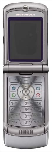
Click to zoom
Application Details
- Equipment Class
- PCE - PCS Licensed Transmitter held to ear
- Date of Grant
- Aug 02, 2006
- Application Purpose
- Original Equipment
- Date of Application
- Jun 11, 2006
- Equipment Note
- Portable Cellular / PCS GSM Transceiver
- Frequency Range
- 824.20000000 - 848.80000000
- Company
- Motorola Mobility LLC
- Country
- United States
Documents & Files
Document Text
Text extracted from the exhibit documents filed with the FCC. Open a document above to read the original.
Users Manual
APPLICANT: MOTOROLA, INC. FCC ID: IHDT56GW1 INSTRUCTION MANUAL • A preliminary draft copy of the User’s Manual follows this cover page. • The User’s Manual will have the following text added to it: "NOTE: This equipment has been tested and found to comply with the limits for a Class B digital device, pursuant to Part 15 of the FCC Rules. These limits are designed to provide reasonable protection against harmful interference in a residential installation. This equipment generates, uses and can radiate radio frequency energy and, if not installed and used in accordance with the instructions, may cause harmful interference to radio communications. However, there is no guarantee that interference will not occur in a particular installation. If this equipment does cause harmful interference to radio or television reception, which can be determined by turning the equipment off and on, the user is encouraged to try to correct the interference by one or more of the following measures: . Reorient or relocate the receiving antenna. . Increase the separation between the equipment and receiver. . Connect the equipment into an outlet on a circuit different from that to which the receiver is connected. . Consult the dealer or an experienced radio/TV technician for help." EXHIBIT 8 motorola.com RAZR V3i GSM Cover.Print.Front.V3i.UG.fm Page 1 Monday, October 3, 2005 10:11 AM Cover.Print.Front.V3i.UG.fm Page 2 Monday, October 3, 2005 10:11 AM 1 HELLOMOTOIntroducing your new Motorola RAZR V3i GSM wireless phone. Navigation Key Navigate menus. Center Key Select menu items. Right Soft KeyiTunes® Digital Jukebox Key Voice Key Power/End Key Turn on/off, hang up, exit menus. Left Soft Key Menu Key Open menus. Volume Keys Smart Key Send Key Make & answer calls. 2 Camera Lens External Display See incoming call information, use as camera viewfinder when camera is active and flip is closed. Bluetooth Indicator Light Accessory Connector Port Insert stereo headset, battery charger, & other phone accessories. Smart Key Take photo when camera is active and flip is closed. Charge indicator Light 3 I M Recent 10/15/07 Exi t Select u n e M n i a M n e e r c S e m o H P ress and hold the P o w er K e y P until the displ a y lights up, to t urn on y our phone. 1 P ress the Cen t er K e y s to select it. 4 P ress the N a vi g ation K e y S up/d o wn/le f t/right to highlight a menu f ea t ure. 3 P ress the Menu K e y a to open the Main Menu . 2 4 Motorola, Inc.Consumer Advocacy Office1307 East Algonquin RoadSchaumburg, IL 60196www.hellomoto.com1-800-331-6456 (United States)1-888-390-6456 (TTY/TDD United States for hearing impaired)1-800-461-4575 (Canada)Certain mobile phone features are dependent on the capabilities and settings of your service provider’s network. Additionally, certain features may not be activated by your service provider, and/or the provider’s network settings may limit the feature’s functionality. Always contact your service provider about feature availability and functionality. All features, functionality, and other product specifications, as well as the information contained in this user’s guide are based upon the latest available information and are believed to be accurate at the time of printing. Motorola reserves the right to change or modify any information or specifications without notice or obligation.MOTOROLA and the Stylized M Logo are registered in the US Patent & Trademark Office. All other product or service names are the property of their respective owners. The Bluetooth trademarks are owned by their proprietor and used by Motorola, Inc. under license. Java and all other Java-based marks are trademarks or registered trademarks of Sun Microsystems, Inc. in the U.S. and other countries. Microsoft and Windows are registered trademarks of Microsoft Corporation; and Windows XP is a trademark of Microsoft Corporation. Macintosh is a registered trademark of Apple Computer, Inc. iTunes is a registered trademark of Apple Computer, Inc. All rights reserved. © Motorola, Inc., 2005, 2006. Caution: Changes or modifications made in the radio phone, not expressly approved by Motorola, will void the user’s authority to operate the equipment. Software Copyright Notice The Motorola products described in this manual may include copyrighted Motorola and third-party software stored in semiconductor memories or other media. Laws in the United States and other countries preserve for Motorola and third-party software providers certain exclusive rights for copyrighted software, such as the exclusive rights to distribute or reproduce the copyrighted software. Accordingly, any copyrighted software contained in the Motorola products may not be modified, reverse-engineered, distributed, or reproduced in any manner to the extent allowed by law. Furthermore, the purchase of the Motorola products shall not be deemed to grant either directly or by implication, estoppel, or otherwise, any license under the copyrights, patents, or patent applications of Motorola or any third-party software provider, except for the normal, non-exclusive, royalty-free license to use that arises by operation of law in the sale of a product.Manual Number: 6809496A88-O contents 5 contentsmenu map. . . . . . . . . . . . 7Use and Care . . . . . . . . . 9essentials . . . . . . . . . . . 10 about this guide . . . . . 10SIM card . . . . . . . . . . . . 11battery . . . . . . . . . . . . . 11turn it on & off . . . . . . 14make a call . . . . . . . . . 14answer a call. . . . . . . . 15store a phone numberin the address book . . 15call a storedphone number . . . . . . 16search theaddress book . . . . . . . 16your phone number . . 16 main attractions . . . . . . 17 iTunes®Digital Jukebox . . . . . . 17memory card . . . . . . . 24airplane mode. . . . . . . 28mobile email . . . . . . . . 29voice commands . . . . 29photos . . . . . . . . . . . . 31video clips. . . . . . . . . . 33multimedia messages 36Bluetooth® wireless. . 38 basics. . . . . . . . . . . . . …
Text truncated - open the document above for the full version.
Attestation Statements
APPLICANT MOTOROLA INC. FCC ID: IHDT56GW1 SPECIFICATION COMPLIANCE STATEMENT Transceiver type FCC ID: IHDT56GW1 has been tested in accordance with the requirements contained in the appropriate Commission regulations. To the best of my knowledge, these tests were performed using measurement procedures consistent with industry or Commission standards and demonstrate that this equipment complies with the appropriate standards. Each unit manufactured imported or marketed, will conform to the sample tested within the variations that can be expected due to quantity production and testing on a statistical basis. I further certify that the necessary measurements were made at: Motorola Personal Communications Sector Product Safety and Compliance Group 600 North US Hwy 45 Libertyville, IL 60048 NAME: Robert Giometti TITLE: Engineering Manager, Personal Communications Sector Date: May 24, 2006 Exhibit 2 APPLICANT MOTOROLA INC. FCC ID: IHDT56GW1 STATEMENT OF CERTIFICATION I hereby certify that the above application was prepared under my direction and that to the best of my knowledge and belief, the facts set forth in this application and accompanying technical data are true and correct. The technical data supplied with this application was taken under my supervision and is hereby duly certified. I also certify that this transmit equipment (FCC ID: IHDT56GW1) is in compliance with all applicable parts of the FCC Rules. NAME: Tadd Scarpelli TITLE: SR. Electrical Engineer Personal Communications Sector Date: May 24, 2006 Exhibit 2
Cover Letter(s)
APPLICANT: MOTOROLA FCC ID: IHDT56GW1 June 15, 2006 CONFIDENTIALITY REQUEST CONTAINED WITHIN Federal Communications Commission Authorization and Evaluation Division 7435 Oakland Mills Road Columbia, Maryland 21046 Re: Application for Cellular/PCS Transceiver Certification Gentlemen: Application: Motorola, Inc., Personal Communications Sector, 600 N. U.S. Highway 45, Libertyville, Illinois 60048-1286 herein submits: Application for Equipment Authorization for Certification of a Cellular Transceiver, FCC ID: IHDT56GW1. Motorola is also the manufacturer of this equipment. Confidentiality: Pursuant to Section 0.459 of the Commission's rules (CFR 47), Motorola requests confidentiality for portions of the material contained in this application and that the identified material be withheld from public inspection following the grant of this authorization. This material contains Motorola's trade secrets and confidential information that Motorola does not customarily release to the public and which is otherwise not generally available to the public. Confidentiality is requested for the following exhibits: • Exhibit 4 Block Diagrams • Exhibit 5 Schematics • Exhibit 12 Operational Description • Exhibit 10 Parts List Description: This equipment is a GSM portable transceiver, which operates in both the 850 MHz and 1900 MHz PCS bands. The unit also contains a power class 1, 2.4 GHz Bluetooth transmitter (Part 15.247). Note: This device contains 900 MHz and 1800 MHz GSM, functions that are not operational in U.S. territories. Contact Information: Please contact me by telephone at (847) 523-6167, or by e-mail ( [email protected]), if there are questions or additional information needed concerning this filing. Regards, Andrew J. Bachler FCC Liaison Cellular Subscriber Sector 600 N. U.S. Highway 45 Libertyville, IL 60048-5343 Exhibit 13
Cover Letter(s)
CRN31136.txt To: Martin Perrine [email protected] FCC Application Processing Branch From: Andrew Bachler, Re: FCC ID IHDT56GW1 Applicant: Motorola Inc Correspondence Reference Number: 31136 731 Confirmation Number: EA226143 For T-coil: Response: Please refer to the Supplement to HAC Test report Submitted on July 10, 2006. For HAC RF emission rating: Response: Please refer to the Supplement to HAC Test report Submitted on July 10, 2006. For SAR 17) Report is titled Class II permissive change..... Please explain this terminology in an original filing. Response: The title of the original filing SAR test report contained a typographical error. The correction has been made to the updated SAR test report. 18) Please justify inclusion of both 15 mm and 25 mm gap data in body worn usage. Response: The 15mm gap data corresponds to SAR measurements taken with the DUT in a voice call. The 25mm gap data corresponds to SAR measurements taken with the DUT in a GPRS Class 10 data connection. The 25mm gap used for data connections corresponds to the "Data Operation" information provided in the Safety and General Information section of the user manual (see exhibit 8A).. 19) Please check table 3 for rounding error. Reduction in SAR is not allowed for positive drift. Response: There is a error in table 3 of the original filing SAR test report. Please see the updated SAR test report for a corrected table 3. 20) Report mentions class 10 capabilities. Class 10 can have 2 time slot operation. Please explain and update the report as necessary. Response: The values in table 4 are results from GPRS Class 10 (2 timeslot) SAR measurements. The values in table 3 are results from GSM (1 timeslot) SAR measurements. 21) User of redefined target values should be handled with care. Please explain how this procedure was addressed in your uncertainty analysis and the overall results. It is expected that this procedure should lower relative uncertainty for validation. Response: The transfer calibration value for 2450 MHz is used for daily system checks only. The text of IEEE 1528 specifically describes and allows this method: [section 8.2.1] "The system check is performed prior to compliance tests and the Page 1 CRN31136.txt result must always be within +/-10% of the target value corresponding to the test frequency, liquid and the source used. The target values are 1g or 10g averaged SARs measured by any system on which system validation has been performed using the system check test system in Figure 8.1". For system checks, the +/-10% tolerance is stated in the standard. System checks are performed daily. Measurement uncertainty, which is utilized during system validation [IEEE 1528, section 8.3], remains unchanged. System validation is performed at least annually. Note: Section 5 of the updated SAR test report has been updated to provide better clarity. 22) Please justify duty factor of 1:1 for BT. Response: There were a couple of errors in Device description table of the original filing SAR test report. Please see the updated SAR test report for a corrected table. 23) Simple SAR summation may not apply for all cases of high power BT. Please justify or repeat with spatial grid summing. Please show locations of all antennas and overlapping SAR scans for worst case conditions. Response: Summation of the measured SAR values to determine the final SAR value of the co-located transmitter was performed in accordance with the guidance provided in IEC 62209-2 (draft), please see the corresponding section of IEC 62209-2 below. This method provides the upper limit of the mulitransmitter SAR. The maximum final SAR value was seen to have ~2dB of margin to the SAR limit and no further investigation was performed. 6.3.2.1 Alternative 1: Assessment by summation of separately assessed maximum SAR values This procedure gives a fast method to determine the upper limit of the multi-band SAR. Assess the maximum mass-averaged SAR at frequency 1 and 2 separately according to section 6.1, or according to IEC 62209-1. Add the two maximum mass-averaged SAR values to obtain the multi-band SAR. For EMC: 24) Please explain any differences in stated and measured power (page 8). Update as appropriate. Response: The form 731 power output is incorrect. Updated values from page 8 of the EMC test report follow: Measurement Results GSM 850: 33.52 dBm (2.249 Watts) ERP GSM 1900: 32.03 dBm (1.596 Watts) EIRP Page 2
External Photos
APPLICANT: MOTOROLA, INC. FCC ID: IHDT56GW1 EXHIBIT 3 Rear View with Battery Cover Removed Showing ID Label Front View Front View Flip Open Rear View
ID Label/Location Info
APPLICANT: MOTOROLA INC. FCC ID: IHDT56GW1 FCC IDENTIFICATION (NAMEPLATE) INFORMATION FCC ID: IHDT56GW1 The FCC label shown is representative of the label that will appear on the radio when in production. It will be placed on the outside of the equipment as shown in Exhibit 3. Other information may also be included on this label. EXHIBIT 1
Internal Photos
APPLICANT: MOTOROLA, INC. FCC ID: IHDT56GW1 EXHIBIT 9 Front View (Shields Removed) Rear View (Shields Removed) Front View Rear View
RF Exposure Info
APPLICANT: MOTOROLA, INC. FCC ID: IHDT56GW1 E E x x h h i i b b i i t t 1 1 1 1 Exhibit 11: Class II Permissive Change SAR Test Report IHDT56GW1 Date of test: Date of Report: 7/9/2005 to 8/4/2005 6/9/2006 Laboratory: Motorola Personal Communications Sector Product Safety & Compliance Laboratory 600 N. US Highway 45 Room: MW113 Libertyville, Illinois 60048 Test Responsible: Paul Ma RF Engineer Accreditation: This laboratory is accredited to ISO/IEC 17025-1999 to perform the following tests: Tests : Procedures: Electromagnetic Specific Absorption Rate ANSI/IEEE C95.1-1992, 1999 (SAR) IEEE C95.3-1991 IEEE 1528, IEC 62209-1 FCC OET Bulletin 65 (including Supplements A, B, C) Australian Communications Authority Radio Communications (Electromagnetic Radiation – Human Exposure) Standard 1999 CENELEC EN 50361 (2001) Simulated Tissue Preparation APP-0247 RF Power Measurement DOI-0876, 0900, 0902, 0904, 0915 On the following products or types of products: Wireless Communications Devices (Examples): Two Way Radios; Portable Phones (including Cellular, Licensed Non-Broadcast and PCS); Low Frequency Readers; and Pagers A2LA certificate #1651-01 Statement of Compliance: Motorola declares under its sole responsibility that portable cellular telephone FCC ID IHDT56GW1 to which this declaration relates, is in conformity with the appropriate General Population/Uncontrolled RF exposure standards, recommendations and guidelines (FCC 47 CFR §2.1093). It also declares that the product was tested in accordance with the appropriate measurement standards, guidelines and recommended practices. Any deviations from these standards, guidelines and recommended practices are noted below: (none) ©Motorola, Inc. 2006 This test report shall not be reproduced except in full, without written approval of the laboratory. The results and statements contained herein relate only to the items tested. The names of individuals involved may be mentioned only in connection with the statements or results from this report. Motorola encourages all feedback, both positive and negative, on this test report. APPLICANT: MOTOROLA, INC. FCC ID: IHDT56GW1 E E x x h h i i b b i i t t 1 1 1 1 P P a a g g e e 2 2 Table of Contents 1. INTRODUCTION ...................................................................................................................................................3 2. DESCRIPTION OF THE DEVICE UNDER TEST.............................................................................................3 2.1 Antenna description ..............................................................................................................................................3 2.2 Device description..................................................................................................................................................3 3. TEST EQUIPMENT USED....................................................................................................................................4 3.1 Dosimetric System .................................................................................................................................................4 3.2 Additional Equipment...........................................................................................................................................4 4. ELECTRICAL PARAMETERS OF THE TISSUE SIMULATING LIQUID ..................................................5 5. SYSTEM ACCURACY VERIFICATION............................................................................................................5 6. TEST RESULTS......................................................................................................................................................6 6.1 Head Adjacent Test Results..................................................................................................................................7 6.2 Body Worn Test Results .......................................................................................................................................9 APPENDIX 1: SAR DISTRIBUTION COMPARISON FOR SYSTEM ACCURACY VERIFICATION .....12 APPENDIX 2: SAR DISTRIBUTION PLOTS FOR PHANTOM HEAD ADJACENT USE ..........................13 APPENDIX 3: SAR DISTRIBUTION PLOTS FOR BODY WORN CONFIGURATION ..............................14 APPENDIX 4: PROBE CALIBRATION CERTIFICATE ..................................................................................15 APPENDIX 5: MEASUREMENT UNCERTAINTY BUDGET..........................................................................16 APPENDIX 6: PHOTOGRAPHS OF DEVICE UNDER TEST...........................................................................19 APPENDIX 7: DIPOLE CHARACTERIZATION CERTIFICATE ..................................................................26 APPLICANT: MOTOROLA, INC. FCC ID: IHDT56GW1 E E x x h h i i b b i i t t 1 1 1 1 P P a a g g e e 3 3 1 Introduction The Motorola Personal Communications Sector Product Safety Laboratory has performed measurements of the maximum potential exposure to the user of portable cellular phone (FCC ID IHDT56GW1). The Specific Absorption Rate (SAR) of this product was measured. The portable cellular phone was tested in accordance with FCC OET Bulletin 65 Supplement C 01-01. 2 Description of the Device Under Test 2.1 Antenna description Type Internal Location Back of Phone Length 15 mm Dimensions Width 40 mm Configuration FICA Antenna 2.2 Device description FCC ID Number IHDT56GW1 Serial number(s) 004400013814544 Mode(s) of Operation GSM 850 GSM 900 GSM 1800 GSM 1900 GPRS 850 GPRS 900 GPRS 1800 GPRS 1900 BlueTooth Modulation Mode(s) GMSK GMSK GMSK GMSK GMSK GMSK GMSK GMSK BT Maximum Output Power Setting 33.00 dBm 33.00 dBm 30.00 dBm 30.00 dBm 33.00 dBm 33.00 dBm 30.00 dBm 30.00 dBm 19.00 dBm Duty Cycle 1:8 1:8 1:8 1:8 2:8 2:8 2:8 2:8 1:1 Transmitting Frequency Rang(s) 824.2- 848.8 MHz 880.2- 914.8 MHz 1710.2- 1784.8MHz 1850.2 – 1909.8 Mhz 824.2-848.8 MHz 8…
Text truncated - open the document above for the full version.
RF Exposure Info
June 28, 2006 Supplement to HAC Test Report for Motorola portable cellular phone (FCC ID IHDT56GW1) Prepared by: Katerina Royzen Motorola Personal Communications Sector Product Safety Laboratory Libertyville, Illinois There was a request for additional information regarding Motorola’s HAC Test Reports for Motorola portable cellular phone (FCC ID IHDT56GW1). The requested information is addressed below in the same numbering sequence received. T - COIL REPORT 2) Please provide more details of how ABM2 is measured by the system. Please demonstrate that the ABM2 measurement is implemented according to C63.19. One option for the later might be to compare expected result progression as each curve is added for a white Gaussian noise input. RESPONSE (provided by Schmid & Partner Engineering, AG): Our processing applies a convolution in the time-domain. This filtering is composed of integrator (straight-forward), Half- Band filter (first-order filter) and A-weighting. The convolved data stream is then integrated over the desired period and represented and stored numerically in DASY4 as the ABM Noise (= ABM2). During the validation process of our system, the functionality of this process has been verified by debugging the filters step-by-step progressive and comparing the results also with a Rohde & Schwarz UPL Analyzer. The intermediate steps are not accessible in the final software code operated by the end user. In addition, the following verification has been made, using a single frequency (sine) signal: At the reference frequency of 1 kHz, the signal is equivalent to ABM1. ABM1 is visible from the calibration job, inclusive its frequency slope from 100Hz to 5kHz. This function (conversion of the coil voltage to the field) is the same integration function. The verification of the probe linearity and the linearity of the integrator has been determined and documented in the certificate 880-SP AM1 001 A, inclusive the integrator, over the required frequency range (exceeding 5 kHz). The additional frequency slope of the Half- Band filter and the A-weighting have also been tested by changing the applied frequency over the full range. The attenuation was verified for each third-octave-band and up to > 10 kHz. In addition, the correct processing of multiple sine-wave signals was verified. The convolutions work over the full frequency range available in the analog path, only limited by AC-coupling at the low end and anti-aliasing filter at the high frequency end. White noise signal without band limitation has not been used for filter measurements. Pink noise, decreasing with frequency, resulting in a frequency independent response of the third-octave filter bank was used to optically verify the correct filtering function. Precision measurements were however made with pure sine signals. Frequency components beyond the visible range of 5 kHz are contained in the ABM2 figure. 3) Please include a demonstration that the probe/system complies with the frequency and linearity response requirements in C63.19 Annex C.5 up to at least 10 KHz. The calibration and ambient noise charts provided only go up to 5 KHz. Significant audio band noise components beyond 10 KHz should be addressed. RESPONSE ( provided by Schmid & Partner Engineering, AG): See also probe certificate of conformity in Appendix 5, titled 880-SP AM1 001 A-A See also coil certificate of conformity in Appendix 6, titled 880-SD HAC P02A-A Frequency response has been tested to be within +/- 0.5 dB of ideal differentiator from 100 Hz to 10 kHz. The test was made with the real integrator and deducting the ideal integrator values. Reference signal was the Helmholtz calibration coil current which is equivalent to the field. The coil is qualified according to certificate 880-SD HAC P02 A-A. The test data up to 5 kHz are visible directly in the calibration job result (coil current / shunt voltage, and probe voltage). Separate measurements were made for a very wide frequency range, including higher frequencies. For the third-octave bands up to 5 kHz do not exceed 0.05 dB and decay by < 0.2 dB to 5 kHz and by < 0.5 dB to 10 kHz, as required. Linearity has also been tested and is stated in the certificate. Deviation was not measurable from 5 dB below limitation to 26 dB above noise level. For lower levels, the deviation increased to 0.1 dB at 16 dB above noise level, which corresponds to the theoretical value of 0.11 dB expected at that noise suppression level. Significant noise contribution beyond 10 kHz will be attenuated by the convoluting A-filter as explained in answer #2. Such interferences contribute also to ABM2 represented as numerical value from the integration. 4) Please provide more details of how the systems make all measurements such as timing, averaging, spectral processing, measurement sequence, and mathematical processing. For frequency response please discuss how input signal level is measured, and how the input source's spectral response is accounted for. RESPONSE: Details regarding timing and averaging of the reported final measured points are as follows: Narrowband Signal Broadband Signal Signal Length (sec): 12 Total Data Acquisition Time per Location (sec): 212 Averaging is over 2 signal repetitions Averaging is over 6 signal repetitions The measurement sequence is contained in section 5.1 of the report. Additional details are as follows: a) Geometry & signal check b) Background noise measurement. The background noise is measured at the center of the listening area. c) Coarse resolution axial scan (narrowband signal, 1sec measurement times, 50x50mm grid with 5.55mm spacing). Only ABM1 is measured in order to find the location of the t-coil source. d) Fine resolution axial, radial-transverse, & radial-longitudinal scans, positioned appropriately based on optimal ABM1 of coarse resolution axial scan (narrowband signal, 1sec measurement times, variable grid size with 2mm spacing). Both ABM1 and ABM2 are measured in order to find the locati…
Text truncated - open the document above for the full version.
RF Exposure Info
FCC Filing IHDT56GW1 – Bluetooth SAR plots overlapping GSM SAR plots for simultaneous transmitter conditions. Applicant: Motorola, Inc.FCC ID: IHDT56GW1 Exhibit 11A
RF Exposure Info
FCC Filing IHDT56GW1 – Bluetooth SAR plots overlapping GSM SAR plots for simultaneous transmitter conditions. Applicant: Motorola, Inc.FCC ID: IHDT56GW1 Exhibit 11A
Test Report
APPLICANT: MOTOROLA INC FCC ID: IHDT56GW1 Test Report Number: 18603-1 EXHIBIT 6 MOBILE DEVICES BUSINESS PRODUCT SAFETY AND COMPLIANCE EMC LABORATORY EMC TEST REPORT Test Report Number – 18603-1 Report Date – June 14, 2006 The test results contained herein relate only to the model(s) identified. It is the manufacturer’s responsibility to assure that additional production units of this model are manufactured with identical electrical and mechanical characteristics. As the responsible EMC Engineer, I hereby declare that the equipment tested as specified in this report conforms to the requirements indicated. Signature: Name: Thanigaiselvan Palaniswami Title: EMC Engineer Date: June 14, 2006 This report must not be reproduced, except in full, without written approval from this laboratory. THIS REPORT MUST NOT BE USED TO CLAIM PRODUCT ENDORSEMENT BY A2LA OR ANY AGENCY OF THE U.S. GOVERNMENT. A2LA Certificate Number: 1651-01 APPLICANT: MOTOROLA INC FCC ID: IHDT56GW1 Test Report Number: 18603-1 EXHIBIT 6 2 Table of Contents Description Page Test Report Details 3 Applicable Standards 3 Summary of Testing 4 General and Special Conditions 4 Equipment and Cable Configuration 5 Measurement Procedures and Data 6 RF Power Output 6 Measurement results 6 Radiated Power 7 Measurement results 7 Occupied Bandwidth 8 Measurement results 9 Spurious Emissions at Antenna Terminals 13 Measurement results 14 Field Strength of Spurious Emissions 16 Measurement results 17 Frequency Stability 19 Measurement results 20 Field Strength of Spurious Emissions -Unintentional Radiators 22 Measurement results 23 AC Line Conducted Emissions 25 Measurement results 26 Appendix A - Radiated Emissions Test Setup Photos 32 Figure A.1 – Radiated Emissions Measurement 32 Figure A.2 – Substitution Measurement 32 APPLICANT: MOTOROLA INC FCC ID: IHDT56GW1 Test Report Number: 18603-1 EXHIBIT 6 3 Test Report Details Tests Performed By: Motorola Mobile Devices business (MDb) Product Safety and Compliance Group 600 North US Hwy 45 Libertyville, IL 60048 PH (847) 523-6167 Fax (847) 523-4538 Motorola MDb FRN: 0004321311 FCC Registration Number: 316588 Industry Canada Number: IC3908-1 Tests Requested By: Motorola Inc. Mobile Devices business 600 North US Hwy 45 Libertyville, IL 60048 Product Type: Cellular Phone Signaling Capability: GSM 850, 1900, Bluetooth FCC ID Number: IHDT56GW1 Serial Numbers: 004400013814692, 004400013814767, 004400013814684, 004400013814718 Testing Complete Date: June 01, 2006 Applicable Standards All tests and measurements indicated in this document were performed in accordance with the Code of Federal Regulations Title 47 Part 2, Sub-part J as well as the following parts: X Part 15 Subpart B – Unintentional Radiators X Part 22 Subpart H - Public Mobile Services X Part 24 - Personal Communications Services Applicable Standards: TIA EIA 137-A, TIA EIA 98-C, ANSI 63.4 2001, RSS-118 (AMPS), RSS-128 (TDMA), RSS-129 (CDMA), RSS-133 (PCS) APPLICANT: MOTOROLA INC FCC ID: IHDT56GW1 Test Report Number: 18603-1 EXHIBIT 6 4 Summary of Testing Test Test Name # Pass/Fail 1 RF Power Output NA 2 ERP (Effective Radiated Power) Pass 3 Occupied Bandwidth Pass 4 Spurious Emissions at Antenna Terminal Pass 5 Field St…
Text truncated - open the document above for the full version.
Contact Information
Applicant
Jeff Narducci(Director Product Compliance)
Technical Specifications
| # | Rule Parts | Frequency Range | Power Output | Emission | Tolerance |
|---|---|---|---|---|---|
| 2 | 22H | 824.2 MHz - 848.8 MHz | 2 W | 250KGXW | 0.1 ppm |
Other Applications from Motorola Mobility LLC
IHDT56AW9
May 12, 2026Smart Watch
Equipment Class
NII - Unlicensed National Information Infrastructure TXIHDT56AW5
Apr 08, 2026Mobile Cellular Phone
Equipment Class
DTS - Digital Transmission SystemIHDT56AW6
Mar 18, 2026Smart Watch
Equipment Class
JBP - Part 15 Class B Computing Device PeripheralIHDT56AX4
Mar 17, 2026Mobile Cellular Phone
Equipment Class
PCE - PCS Licensed Transmitter held to earIHDT56AW3
Mar 03, 2026Mobile Cellular Phone
Equipment Class
6XD - 15E 6 GHz Low Power Indoor Client