IHDT56HW2Portable Cellular/ PCS GSM/ EDGE Transceiver w/ BT
Motorola Mobility LLC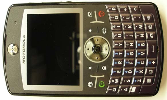
Click to zoom
Application Details
- Equipment Class
- JBP - Part 15 Class B Computing Device Peripheral
- Date of Grant
- Feb 14, 2007
- Application Purpose
- Original Equipment
- Date of Application
- Feb 12, 2007
- Equipment Note
- Portable Cellular/ PCS GSM/ EDGE Transceiver w/ BT
- Company
- Motorola Mobility LLC
- Country
- United States
Documents & Files
Document Text
Text extracted from the exhibit documents filed with the FCC. Open a document above to read the original.
Users Manual
INSTRUCTION MANUAL A preliminary draft of the User’s Manual follows this page. The text on the following three pages will be added to the user manual. APPLICANT: MOTOROLA,INC. FCC ID: IHDT56GW1 EXHIBIT 8 SAR DataSpecific Absorption Rate DataSAR DataThis model wireless phone meets the government’s requirements for exposure to radio waves.Your wireless phone is a radio transmitter and receiver. It is designed and manufactured not to exceed limits for exposure to radio frequency (RF) energy set by the Federal Communications Commission (FCC) of the U.S. Government and by the Canadian regulatory authorities. These limits are part of comprehensive guidelines and establish permitted levels of RF energy for the general population. The guidelines are based on standards that were developed by independent scientific organizations through periodic and thorough evaluation of scientific studies. The standards include a substantial safety margin designed to assure the safety of all persons, regardless of age or health.The exposure standard for wireless mobile phones employs a unit of measurement known as the Specific Absorption Rate, or SAR. The SAR limit set by the FCC and by the Canadian regulatory authorities is 1.6 W/kg. 1 Tests for SAR are conducted using standard operating positions accepted by the FCC and by Industry Canada with the phone transmitting at its highest certified power level in all tested frequency bands. Although the SAR is determined at the highest certified power level, the actual SAR level of the phone while operating can be well below the maximum value. This is because the phone is designed to operate at multiple power levels so as to use only the power required to reach the network. In general, the closer you are to a wireless base station, the lower the power output.Before a phone model is available for sale to the public in the U.S. and Canada, it must be tested and certified to the FCC and Industry Canada that it does not exceed the limit established by each government for safe exposure. The tests are performed in positions and locations (e.g., at the ear and worn on the body) reported to the FCC and available for review by Industry Canada. The highest SAR value for this model phone when tested for use at the ear is 0 . 7 0 W/kg, and when worn on the body, as described in this user guide, is 0. 7 9 W/kg. The SAR value for this product in its data transmission mode (body-worn use) is 0. 26 W/kg. (Body-worn measurements differ among phone models, depending upon available accessories and regulatory requirements). 2 While there may be differences between the SAR levels of various phones and at various positions, they all meet the governmental requirements for safe exposure. Please note that improvements to this product model could cause differences in the SAR value for later products; in all cases, products are designed to be within the guidelines. SAR Data Additional information on Specific Absorption Rates (SAR) can be found on the Cellular Telecommunications & Internet Association (CTIA) Web site:http://www.phonefacts.netor the Canadian Wireless Telecommunications Association (CWTA) Web site:http://www.cwta.ca1. In the United States and Canada, the SAR limit for mobile phones used by the public is 1.6 watts/kg (W/kg) averaged over one gram of tissue. The standard incorporates a substantial margin of safety to give additional protection for the public and to account for any variations in measurements. 2. The SAR information includes the Motorola testing protocol, assessment procedure, and measurement uncertainty range for this product. FCC NoticeFCC Notice To UsersFCC NoticeMotorola has not approved any changes or modifications to this device by the user. Any changes or modifications could void the user’s authority to operate the equipment. See 47 CFR Sec. 15.21.This device complies with part 15 of the FCC Rules. Operation is subject to the following two conditions: (1) This device may not cause harmful interference, and (2) this device must accept any interference received, including interference that may cause undesired operation. See 47 CFR Sec. 15.19(3).If your mobile device or accessory has a USB connector, or is otherwise considered a computer peripheral device whereby it can be connected to a computer for purposes of transferring data, then it is considered a Class B device and the following statement applies:This equipment has been tested and found to comply with the limits for a Class B digital device, pursuant to part 15 of the FCC Rules. These limits are designed to provide reasonable protection against harmful interference in a residential installation. This equipment generates, uses and can radiate radio frequency energy and, if not installed and used in accordance with the instructions, may cause harmful interference to radio communications. However, there is no guarantee that interference will not occur in a particular installation. If this equipment does cause harmful interference to radio or television reception, which can be determined by turning the equipment off and on, the user is encouraged to try to correct the interference by one or more of the following measures: • Reorient or relocate the receiving antenna. • Increase the separation between the equipment and the receiver. • Connect the equipment to an outlet on a circuit different from that to which the receiver is connected. • Consult the dealer or an experienced radio/TV technician for help. 1 HELLOMOTOIntroducing your new MOTO Q™ q9 wireless phone! You can use the QWERTY keypad for e-mail and text messages . You can use Bluetooth™ wireless headsets to hear calls or music. Here’s a quick anatomy lesson. N a v iga t i on Key Navigate m enus. Center KeySelect m enu ite m s. Mess agi n g Key Power/End Key Turn on & off, hang up, exit m enus. S i de S c roll Keys B ac k Keys Enter KeyC ap s Key S i de Sele c t Key R ig ht Soft Key S p e a ker p hone/Vo ic e Re c o g n i t i on Key C a mer a Key Mult i …
Text truncated - open the document above for the full version.
Attestation Statements
APPLICANT: MOTOROLA INC. FCC ID: IHDT56HW2 SPECIFICATION COMPLIANCE STATEMENT Transceiver type (IHDT56HW2) has been tested in accordance with the requirements contained in the appropriate Commission regulations. To the best of my knowledge, these tests were performed using measurement procedures consistent with industry or Commission standards and demonstrate that this equipment complies with the appropriate standards. Each unit manufactured imported or marketed, will conform to the sample tested within the variations that can be expected due to quantity production and testing on a statistical basis. I further certify that the necessary measurements were made at Motorola, 600 N. U.S. Highway 45, Libertyville, IL 60048. NAME: Dan Flondro TITLE: Engineering Manager Motorola Mobile Devices Business Date: Feb. 2, 2007 Page 1 of 3 EXHIBIT 2 APPLICANT: MOTOROLA INC. FCC ID: IHDT56HW2 STATEMENT OF CERTIFICATION I hereby certify that the above application was prepared under my direction and that to the best of my knowledge and belief, the facts set forth in this application and accompanying technical data are true and correct. The technical data supplied with this application was taken under my supervision and is hereby duly certified. I also certify that this transmit equipment (IHDT IHDT56HW2) is in compliance with all applicable parts of the FCC Rules. NAME: Dan Flondro TITLE: Engineering Manager Motorola Mobile Devices Business Date: Feb. 2, 2007 Page 2 of 3 EXHIBIT 2 APPLICANT: MOTOROLA INC. FCC ID: IHDT56HW2 ATTESTATION STATEMENT This device contains an embedded Bluetooth device that Motorola confirms compliance with the following Part 15 regulations. 15.247(a)(1) • the hopping sequence must be pseudorandom • all Channels are used equally on average • the receiver input bandwidth is approximately equal to the transmit bandwidth • the receiver hops in sequence with the transmitted signal 15.247(g) the system is designed to comply with all of the regulations in Section 15.247 when the transmitter is presented with a continuous data (or information) 15.247(h) the system does not coordinate its channel selection/hopping sequence with other frequency hopping systems for the express purpose of avoiding the simultaneous occupancy of individual hopping frequencies by multiple transmitters NAME: Dan Flondro TITLE: Engineering Manager Mobile Device Business Motorola, Inc. Date: Feb. 2, 2007 Page 3 of 3 EXHIBIT 2
Cover Letter(s)
APPLICANT: MOTOROLA, INC. FCC ID: IHDT56HW2 February 2, 2007 SHORT TERM CONFIDENTIALITY REQUEST 45 DAYS Federal Communications Commission Authorization and Evaluation Division 7435 Oakland Mills Road Columbia, Maryland 21046 Re: Cellular/PCS Transceiver FCC ID IHDT56HW2 Gentlemen: Introduction: Pursuant to Section 0.459 of the Commission's rules (CFR 47) and Section 552(b)(4) of the Freedom of Information Act, Motorola requests confidentiality for portions of the material contained in this application; and that the identified material be withheld from public inspection following the grant of this authorization. This material contains Motorola's trade secrets and confidential information that Motorola does not customarily release to the public and which is otherwise not generally available to the public. Standard Confidentiality Request: Confidentiality is requested for the following exhibits: • Exhibit 4 Block Diagrams • Exhibit 5 Schematics • Exhibit 10 Parts List / Tune up Information • Exhibit 12 Operational Description Short Term Confidentiality Request: Furthermore, due to sensitive business information, Motorola requests the following exhibits be withheld from public viewing for 45 days: • Exhibit 3 External Photographs • Exhibit 7 and 7A Test Setup Photographs • Exhibit 8 User’s Manual • Exhibit 9 Internal Photographs Contact Information: Please contact me by telephone at (847) 523-6167, or by e-mail ( [email protected]), if there are questions or additional information needed concerning this filing. Regards, Andrew J. Bachler FCC Liaison Mobile Devices 600 N. U.S. Highway 45 Libertyville, IL 60048-5343 Exhibit 13A
Cover Letter(s)
Date: February 12, 2007 Subject: Request for additional information regarding FCC ID: IHDT56HW2 Reference: Correspondence Reference Number: IHD7083 Confirmation Number: 702070083-85 Date of Original Email: February 9, 2007 Prepared by: Andrew Bachler, Principal Staff Engineer Motorola Mobile Device Business Libertyville, Illinois 1. Several items in the Part 22/24 EMC, Part 15B and Part 15C test reports are listed as past their cal due dates. Please address. Response: All testing was performed using equipment that was within calibration at the time that the test was performed. No equipment listed in the equipment table was used after the specified calibration due date. If, during the course of product testing, a piece of equipment went out of calibration and that piece of equipment was needed to complete product testing, a similar piece of calibrated equipment was substituted. If a substitution was made, that new piece of equipment would be listed in the equipment table along with the piece that was removed from service. 2. Please verify that the measured ERP of 850 EDGE is more than 10 dB lower than the measured 850 GSM ERP. Response: The 850 EDGE ERP data in the report accurately reflects the measurement results. 3. Please provide a copy of the ISO/IEC 17025 Accreditation for the test labs used to perform testing on the EUT (including EMC (Parts 22/24 and 15) and SAR). These accreditations do not appear to be available on the A2LA website. Response: The copy can be found at the following link. Please copy and paste into your web browser. http://www.a2la.org/scopepdf/2518-02.pdf 1
External Photos
APPLICANT: MOTOROLA, INC. FCC ID: IHDT56HW2 FRONT OF PHONE BACK OF PHONE EQUIPMENT ID LABEL LOCATION BACK OF PHONE WITH BATTERY COVER REMOVED EXHIBIT 3
ID Label/Location Info
APPLICANT: MOTOROLA INC. FCC ID: IHDT56HW2 FCC IDENTIFICATION (NAMEPLATE) INFORMATION FCC ID: IHDT56HW2 The FCC label shown is representative of the label that will appear on the radio when in production. It will be placed on the outside of the equipment as shown in Exhibit 3, and is readily visible at the time of purchase. Other information may also be included on this label. EXHIBIT 1
Internal Photos
APPLICANT: MOTOROLA, INC. FCC ID: IHDT56HW2 Main Board Front (With Shields) Main Board Front (Without Shields) EXHIBIT 4 Page 1 of 5 APPLICANT: MOTOROLA, INC. FCC ID: IHDT56HW2 Main Board Back (Without Shields) Main Board Back (Without Shields) EXHIBIT 4 Page 2 of 5 APPLICANT: MOTOROLA, INC. FCC ID: IHDT56HW2 Daughter Board Front (Without Shields and Camera Module) Daughter Board Front (With Shields and Camera Module) Daughter Board Back (With Camera Module) Daughter Board Front (Without Camera Module) EXHIBIT 4 Page 3 of 5 APPLICANT: MOTOROLA, INC. FCC ID: IHDT56HW2 Main and Daughter Boards (Connected Together) EXHIBIT 4 Page 4 of 5 APPLICANT: MOTOROLA, INC. FCC ID: IHDT56HW2 Inside Front Housing Inside Back Housing EXHIBIT 4 Page 5 of 5
Test Report
APPLICANT: MOTOROLA INC FCC ID: IHDT56HW2 Test Report Number: 19881-1 Supplement 1 of 10 EXHIBIT 6A3 MOBILE DEVICES BUSINESS PRODUCT SAFETY AND COMPLIANCE EMC LABORATORY EMC TEST REPORT Test Report Number – 19881-1 Supplement Report Date – January 30, 2007 The test results contained herein relate only to the model(s) identified. It is the manufacturer’s responsibility to assure that additional production units of this model are manufactured with identical electrical and mechanical characteristics. As the responsible EMC Engineer, I hereby declare that the equipment tested as specified in this report conforms to the requirements indicated. Signature: Name: Albert J. Patapack Title: EMC Engineer Date: January 30, 2007 This report must not be reproduced, except in full, without written approval from this laboratory. THIS REPORT MUST NOT BE USED TO CLAIM PRODUCT ENDORSEMENT BY A2LA OR ANY AGENCY OF THE U.S. GOVERNMENT. A2LA Certificate Number: 2518-02 APPLICANT: MOTOROLA INC FCC ID: IHDT56HW2 Test Report Number: 19881-1 Supplement 2 of 10 EXHIBIT 6A3 Table of Contents Description Page Test Report Details 3 Applicable Standards 3 Summary of Testing 4 General and Special Conditions 4 Equipment and Cable Configuration 5 Measurement Procedures and Data 6 APPLICANT: MOTOROLA INC FCC ID: IHDT56HW2 Test Report Number: 19881-1 Supplement 3 of 10 EXHIBIT 6A3 Test Report Details Tests Performed By: Motorola Mobile Devices business (MDb) Product Safety and Compliance Group 600 North US Hwy 45 Libertyville, IL 60048 PH (847) 523-6167 Fax (847) 523-4538 Motorola MDb FRN: 0004321311 FCC Registration Number: 316588 Industry Canada Number: IC3908-1 Tests Requested By: Motorola Inc. Mobile Devices business 600 North US Hwy 45 Libertyville, IL 60048 Signaling Capability: GSM 850, GSM 1900, EDGE, Bluetooth FCC ID : IHDT56HW2 Serial Numbers: 1NE0620061, 1NE0620010, 1NE0620029 1NE0620047, 1NE0620002 Testing Complete Date: January 30, 2007 Applicable Standards All tests and measurements indicated in this document were performed in accordance with the Code of Federal Regulations Title 47 : X Part 15 Subpart B – Unintentional Radiators Applicable Standards: ANSI 63.4 2003 APPLICANT: MOTOROLA INC FCC ID: IHDT56HW2 Test Report Number: 19881-1 Supplement 4 of 10 EXHIBIT 6A3 Summary of Testing Test Test Name # Pass/Fail _________ 1 Field Strength of Spurious Emissions Pass from Unintentional Radiators 2 AC Line Conducted Emissions Pass Test Test Name Margin with respect # to the Limit_________ 1 Field Strength of Spurious Emissions see results from Unintentional Radiators 2 AC Line Conducted Emissions see results The margin with respect to the limit is the minimum margin for all modes and bands. General and Special Conditions The EUT was tested using a fully charged battery. All testing was done in an indoor controlled environment with an average temperature of 22º C and relative humidity of 50%. APPLICANT: MOTOROLA INC FCC ID: IHDT56HW2 Test Report Number: 19881-1 Supplement 5 of 10 EXHIBIT 6A3 Equipment List Manufacturer Equipment Type Model No. Serial Number Calibration Due Date Rohde Schwarz Receiver ESI26 100001 3/08/07 Rohde Schwarz Receiver ESI40 100226 6/05/07 A.H. Systems Inc. DRG Horn Antenna SAS 200/571 365 5/12/07 ETS Log-Periodic Antenna 3148 1188 6/05/07 ETS Biconical Antenna 3110B 3370 3/03/07 Attenuator Weinschel AS-6 7075 6/29/07 Attenuator Weinschel AS-6 6675 1/06/07 Attenuator Weinschel AS-6 7074 06/29/07 ETS LISN 3810/2NM 00062907 5/10/07 ETS LISN 3810/2NM 00062912 5/10/07 Dell Laptop Computer M20 NA NA Iomega Zip Drive Z250S P9HM1992CK NA Olympus Camera D-600L 4020727 NA All equipment is on a one-year calibration cycle. The Dell M20 Laptop Computer, the Iomega Z250S Zip Drive and the Olympus D-600L Camera are labeled as DoC. APPLICANT: MOTOROLA INC FCC ID: IHDT56HW2 Test Report Number: 19881-1 Supplement 6 of 10 EXHIBIT 6A3 Measurement Procedures and Data FIELD STRENGTH OF EMISSIONS FROM UNINTENTIONAL RADIATORS Measurement Procedure The equipment under test is placed inside the semi-anechoic chamber on a wooden table on the turntable center. For each radiated emission, the antenna mast is raised and lowered from 1 to 4 meters and the turntable is rotated 360 degrees to obtain a maximum peak reading on the spectrum analyzer. The final radiated emissions are then measured using an EMI receiver employing a CISPR quasi-peak detector function below 1000 MHz and an average detector function above 1000 MHz. This is repeated for both horizontal and vertical polarizations of the receive antenna. The field strength of each radiated emission is calculated by correcting the EMI receiver level for cable loss, amplifier gain, and antenna correction factors. Field Strength (dBuV/m) = EMI Receiver Level (dBuV) + Cable Loss (dB) - Amplifier Gain (dB) + Antenna Correction Factor (1/m) Test Setup The EUT and the host equipment were setup according to the procedures in ANSI C63.4- 2003. The EUT was connected to a laptop computer using a USB data cable. The USB data cable is 1 m in length. The parallel and the serial ports of the computer were populated. The EUT was communicating with the laptop computer continuously. APPLICANT: MOTOROLA INC FCC ID: IHDT56HW2 Test Report Number: 19881-1 Supplement 7 of 10 EXHIBIT 6A3 Measurement Results Operating Mode – Rx Mode, Data Transfer Mode. 30 MHz – 1000 MHz Frequency MHz Level dBμV/m Measured dBμV Transd dB Cables dB Limit dBμV/m Margin dB Height cm Angle deg Pol. 34.88 32.91 12.77 12.3 7.8 40 7.1 121 147 VERT 72.00 33.09 15.41 9.0 8.7 40 6.9 100 241 VERT 147.28 36.36 13.21 13.1 10.1 43.5 7.1 100 167 VERT 196.36 39.19 13.42 15.2 10.6 43.5 4.3 170 221 HORI 906.48 39.35 -0.41 23.8 15.9 46 6.7 125 359 HORI 913.88 39.81 -0.46 24.3 15.9 46 6.2 190 135 HORI Above 1 GHz Frequency MHz Level dBμV/m Measured dBμV Transd dB Gain dB Limit dBμV/m Margin dB Height cm Angle deg Pol. 1119.1 38.86 23.83 23.8 8.8 53.9 15 124 98 VERT 1130.6 40.6 25.37 23.9 8.7 53.9 13.3 111 96 VERT 1512.6 37.72 …
Text truncated - open the document above for the full version.
Test Setup Photos
Motorola EMC TEST SETUP PHOTOS Motorola EMC Report #19881-1, AC Line - Part 15 APPLICANT: MOTOROLA, INC. FCC ID: IHDT56HW2 Page 1 of 9 EXHIBIT 7 Motorola EMC Report #19881-1, Part 15, PC Peripheral APPLICANT: MOTOROLA, INC. FCC ID: IHDT56HW2 Page 2 of 9 EXHIBIT 7 Motorola EMC Report #19881-1, Antenna - Substitution APPLICANT: MOTOROLA, INC. FCC ID: IHDT56HW2 Page 3 of 9 EXHIBIT 7 Motorola EMC Report #19881-1, Tx Radiated APPLICANT: MOTOROLA, INC. FCC ID: IHDT56HW2 Page 4 of 9 EXHIBIT 7 MOTOROLA, INC. Portable Cellular Phone SAR Test Report Number: 19888-1F E E x x h h i i b b i i t t 1 1 1 1 P P a a g g e e 2 2 1 1 Appendix 6 (PULLED FROM FCC EXHIBIT 11) Photographs of the device under test APPLICANT: MOTOROLA, INC. FCC ID: IHDT56HW2 Page 5 of 9 EXHIBIT 7 MOTOROLA, INC. Portable Cellular Phone SAR Test Report Number: 19888-1F E E x x h h i i b b i i t t 1 1 1 1 P P a a g g e e 2 2 2 2 Figure 1 – Front of Transceiver Figure 2 – Back of Transceiver (Showing Standard and Extended Battery Doors) APPLICANT: MOTOROLA, INC. FCC ID: IHDT56HW2 Page 6 of 9 EXHIBIT 7 MOTOROLA, INC. Portable Cellular Phone SAR Test Report Number: 19888-1F E E x x h h i i b b i i t t 1 1 1 1 P P a a g g e e 2 2 3 3 Figure 3 – Transceiver against head, Cheek Touch position Figure 4 – Transceiver against head, Cheek Touch position APPLICANT: MOTOROLA, INC. FCC ID: IHDT56HW2 Page 7 of 9 EXHIBIT 7 MOTOROLA, INC. Portable Cellular Phone SAR Test Report Number: 19888-1F E E x x h h i i b b i i t t 1 1 1 1 P P a a g g e e 2 2 4 4 Figure 5 – Transceiver against head, 15º Tilt position Figure 6 – Transceiver against head, 15º Tilt position APPLICANT: MOTOROLA, INC. FCC ID: IHDT56HW2 Page 8 of 9 EXHIBIT 7 MOTOROLA, INC. Portable Cellular Phone SAR Test Report Number: 19888-1F E E x x h h i i b b i i t t 1 1 1 1 P P a a g g e e 2 2 5 5 Figure 7 – Transceiver against body, Back of Phone 15 mm from Phantom position Figure 8 – Transceiver against body with Pouch accessory APPLICANT: MOTOROLA, INC. FCC ID: IHDT56HW2 Page 9 of 9 EXHIBIT 7
Test Setup Photos
FCC ID - IHDT56HW2 File MC15003 Project 07CA04810 Page A1 of A2 UL International EMC Services www.ul.com/hitech/emc (800) USE UL EMC APPENDIX A PHOTOS FCC ID - IHDT56HW2 File MC15003 Project 07CA04810 Page A2 of A2 UL International EMC Services www.ul.com/hitech/emc (800) USE UL EMC Radiated Emissions X-Axis . Radiated Emissions Y-Axis Radiated Emissions Z-Axis
Contact Information
Applicant
Jeff Narducci(Director Product Compliance)
Technical Contact
PCTEST Engineering Laboratory, Inc.Randy Ortanez
[email protected]410-290-6652
6660-B Dobbin Road · Columbia, Maryland · United States
Test Firm
Motorola Inc.Albert Patapack
Technical Specifications
| # | Rule Parts | Frequency Range | Power Output |
|---|---|---|---|
| 1 | 15B | - | - |
Other Applications from Motorola Mobility LLC
IHDT56AW9
May 12, 2026Smart Watch
Equipment Class
NII - Unlicensed National Information Infrastructure TXIHDT56AW5
Apr 08, 2026Mobile Cellular Phone
Equipment Class
DTS - Digital Transmission SystemIHDT56AW6
Mar 18, 2026Smart Watch
Equipment Class
JBP - Part 15 Class B Computing Device PeripheralIHDT56AX4
Mar 17, 2026Mobile Cellular Phone
Equipment Class
PCE - PCS Licensed Transmitter held to earIHDT56AW3
Mar 03, 2026Mobile Cellular Phone
Equipment Class
6XD - 15E 6 GHz Low Power Indoor Client