IHDT56ZF1Portable Cellular Transceiver
Motorola Mobility LLC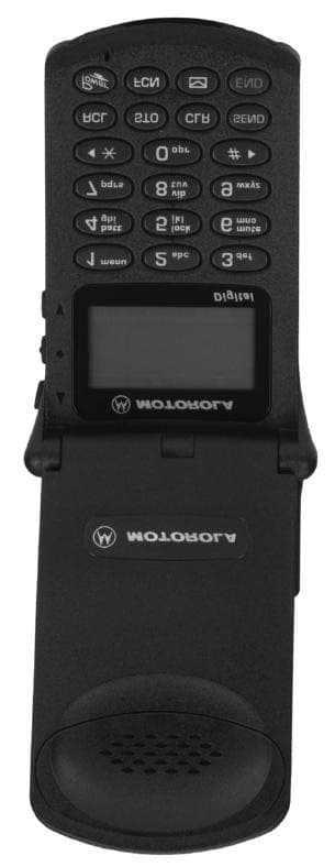
Click to zoom
Application Details
- Equipment Class
- TNE - Licensed Non-Broadcast Transmitter Held to Ear
- Date of Grant
- Jul 29, 1999
- Application Purpose
- Original Equipment
- Date of Application
- May 03, 1999
- Equipment Note
- Portable Cellular Transceiver
- Frequency Range
- 1850.01000000 - 1909.95000000
- Company
- Motorola Mobility LLC
- Country
- United States
Documents & Files
Document Text
Text extracted from the exhibit documents filed with the FCC. Open a document above to read the original.
Users Manual
APPLICANT: MOTOROLA, INC.FCC ID: IHDT56ZF1 INSTRUCTION MANUAL EXHIBIT 8 The following is a draft copy of the instruction manual. TDMA StarTAC Cellular Telephone User Manual Engineering Review—April 6, 1999 Welcome All Motorola digital cellular phones are designed and manufactured to meet Motorola’s rigorous specifications and world-class quality standards. During development, our laboratory testing team took the Digital StarTAC™ cellular phone through rigorous durability tests including temperature, humidity, shock, dust, vibration, and drop tests— and the phone still worked! We are confident that the phone you purchased will meet your own exacting standards. Thank you for choosing Motorola, a global leader in communications technology. Enjoy your Digital StarTAC™ phone. iv Contents Welcome . . . . . . . . . . . . . . . . . . . . . . . . . . . . . . . . 3 Safety Information . . . . . . . . . . . . . . . . . . . . . . . . 7 Overview . . . . . . . . . . . . . . . . . . . . . . . . . . . . . . . 12 Package Content Options . . . . . . . . . . . . . . . . 12 Phone Overview . . . . . . . . . . . . . . . . . . . . . . . . 13 Understanding the Guide . . . . . . . . . . . . . . . . 14 Using the Battery . . . . . . . . . . . . . . . . . . . . . . . . 15 About Your Batteries . . . . . . . . . . . . . . . . . . . . 15 Removing and Attaching Battery Covers . . . . 17 Installing and Removing Batteries . . . . . . . . . . 18 Checking Battery Levels . . . . . . . . . . . . . . . . . 19 Charging Batteries . . . . . . . . . . . . . . . . . . . . . . 20 Using the Phone . . . . . . . . . . . . . . . . . . . . . . . . . 24 Turning the Phone On and Off . . . . . . . . . . . . . 24 Reading the Indicators . . . . . . . . . . . . . . . . . . 25 Standby Mode . . . . . . . . . . . . . . . . . . . . . . . . . 27 Holding Your Phone . . . . . . . . . . . . . . . . . . . . . 27 Storing Your Phone in Its Holster . . . . . . . . . . . 28 Placing a Call . . . . . . . . . . . . . . . . . . . . . . . . . . 28 Ending a Call . . . . . . . . . . . . . . . . . . . . . . . . . . 28 Viewing Your Own Number . . . . . . . . . . . . . . . 29 Receiving a Call . . . . . . . . . . . . . . . . . . . . . . . . 29 Switching Between Digital and Analog Modes 29 Using the Smart Button . . . . . . . . . . . . . . . . . . 30 Redialing a Number . . . . . . . . . . . . . . . . . . . . . 31 Controlling Volume . . . . . . . . . . . . . . . . . . . . . . 32 Using Memory . . . . . . . . . . . . . . . . . . . . . . . . . . 33 Using Your Phone’s Built-in Phone Book 34 Storing Names and Numbers . . . . . . . . . . . . . 34 Recalling an Entry by Name . . . . . . . . . . . . . . 36 Recalling an Entry by Memory Location . . . . . 36 Clearing a Memory Entry . . . . . . . . . . . . . . . . . 37 Shortcuts for Recalling Phone Book Entries . . 37 Making Notes on the Scratchpad . . . . . . . . . . 38 Using the Menu System . . . . . . . . . . . . . . . . . . . 39 v Navigating the Menu . . . . . . . . . . . . . . . . . . . .39 Road Maps 40 Managing the Phone Book . . . . . . . . . . . . . . . . .41 Road Map for Phone Book 42 Recalling an Entry by Name . . . . . . . . . . . . . . .43 Recalling an Entry by Location . . . . . . . . . . . .43 Storing with the Menu . . . . . . . . . . . . . . . . . . . .44 Storing and Placing Numbers With Pause Dialing 45 Storing and Placing Numbers for Calling Card Information . . . . . . . . . . . . . . . . . . . . . . . . . . . .47 Editing a Memory Location . . . . . . . . . . . . . . .50 Viewing Your Own Number . . . . . . . . . . . . . . . .52 Phone Book Display Preferences 53 Timing Your Calls . . . . . . . . . . . . . . . . . . . . . . . .54 Road Map for Call Timers 55 Viewing the Individual Call Timer . . . . . . . . . . .56 Viewing the Resettable Call Timer . . . . . . . . . .56 Viewing the Cumulative Timer . . . . . . . . . . . . .57 Resetting the Timer . . . . . . . . . . . . . . . . . . . . .57 Displaying the Individual Timer Automatically .58 Setting the One-Minute Audible Timer . . . . . . .58 Setting the Repeating Audible Timer . . . . . . . .59 Setting the Single Timer . . . . . . . . . . . . . . . . . .59 Adjusting Tone Controls . . . . . . . . . . . . . . . . . . .61 Road Map for Tone Controls 62 Using Call Alert Tones . . . . . . . . . . . . . . . . . . .63 Selecting a Ringer Style 64 Using Message Alert Tones . . . . . . . . . . . . . . .64 Turning Keypad Tones On and Off . . . . . . . . . .65 Turning Scratchpad Tones On and Off . . . . . . .65 Using Lock/Security Features . . . . . . . . . . . . . .67 Road Map for Lock Security 68 Activating Voice Privacy . . . . . . . . . . . . . . . . . .69 Locking/Unlocking Your Phone . . . . . . . . . . . .70 Activating Priority Calling . . . . . . . . . . . . . . . . .71 Managing Security Options . . . . . . . . . . . . . . .72 Customizing Phone Features . . . . . . . . . . . . . . .79 Road Map for Phone Options 80 Selecting Call Mode Preference . . . . . . . . . . . .81 vi Switching Between Numbers . . . . . . . . . . . . . 82 Selecting a Cellular System . . . . . . . . . . . . . . 83 Reviewing Feature Settings . . . . . . . . . . . . . . . 84 Blocking Incoming Calls . . . . . . . . . . . . . . . . . 85 Activating Automatic Hands-Free . . . . . . . . . . . . . . . . . . . . . . . . . . . 85 Activating Multiple Key Answer . . . . . . . . . . . . 86 Activating Open to Answer . . . . . . . . . . . . . . . 86 Activating Automatic Answer . . . . . . . . . . . . . . 87 Selecting Battery Options—Power Save Mode 88 Displaying System Identification . . . . . . . . . . . 88 Selecting Language . . . . . . . . . . . . . . . . . . . . 89 Using the Message Center . . . . . . . . . . . . . . . . 90 Road Map for Message Center 91 Using Short Messaging . . . . . . . . . . . . . . . . . . 92 Using Voice Mail . . . . . . . . . . . . . . . . . . . . . . . 97 Using Caller ID . . . . . . . . . . . . . . . . . . . . . . . . 97 Setting the Scrolling Speed . . . . . . . . . . . . . . 100 Selecting …
Text truncated - open the document above for the full version.
Attestation Statements
APPLICANT: MOTOROLAFCC ID: IHDT56ZF1 EXHIBIT 2A April 30, 1999 SPECIFICATION COMPLIANCE STATEMENT Engineer-in-Charge Equipment Authorization Branch Federal Communications Commission We hereby certify that this transmit and receive equipment (FCC ID: IHDT56ZF1) for dual mode, dual band mobile station cellular use is capable of full compliance with TIA/EIA-136 (Revision 0), Dual-Mode, Dual- Band Mobile Station - Base Station Compatibility Standard, October 1998, (Signed – Robert J. Bero) Rob Bero Engineering Section Manager Cellular Subscriber Equipment (Signed – Paul Krayeski) Paul Krayeski Engineering Manager Cellular Subscriber Equipment EXHIBIT 2B APPLICANT: MOTOROLA, INC.FCC ID: IHDT56ZF1 STATEMENT OF CERTIFICATION The technical data supplied with this application, having been taken under my supervision is hereby duly certified. The following is a statement of my qualifications: BSEE 1991 University of Wisconsin 7 years Cellular Design Experience SIGNATURE:(signed) Robert J. Bero NAME:Rob Bero DATE:4/30/99 POSITION:Engineering Section Manager I hereby certify that the above application was prepared under my direction and that to the best of my knowledge and belief, the facts set forth in the application and accompanying technical data are true and correct: SIGNATURE:(signed) Paul Krayeski NAME:Paul Krayeski DATE:4/30/99 POSITION:Engineering Manager APPLICANT: MOTOROLA, INC.FCC ID: IHDT56ZF1 EXHIBIT 2C RADIO FREQUENCY ENERGY EXPOSURE EVALUATION STATEMENT Motorola, Inc., Personal Communications Sector, hereby certifies that, when used as stated in the operating instructions supplied, this Cellular/PCS Portable Transceiver, FCC ID: IHDT56ZF1, complies with the FCC's Radio frequency energy exposure limits for General Population/Uncontrolled environment, per FCC Rule 47CFR2.1093.
Cover Letter(s)
APPLICANT: MOTOROLAFCC ID: IHDT56ZF1 Exhibit 13 April 30, 1999 CONFIDENTIALITY REQUEST CONTAINED WITHIN Federal Communications Commission Authorization and Evaluation Division 7435 Oakland Mills Road Columbia, Maryland 21046 Re: Application for Cellular/PCS Transceiver Type Acceptance Gentlemen: Application: Motorola, Inc., Pan American Cellular Subscriber Group, 600 N. U.S. Highway 45, Libertyville, Illinois 60048-1286 herein submits: Application for Equipment Authorization (FCC Form 731- October 1992 with integrated Fee Processing Form, Fee Codes EFT and EBT), Check Number 119-657678 in the amount of $610 and Exhibits, for Type Acceptance of a Cellular Transceiver, FCC ID: IHDT56ZF1. Motorola is also the manufacturer of this equipment. Confidentiality: Pursuant to Section 0.459 of the Commission's rules (CFR 47), Motorola requests confidentiality for portions of the material contained in this application and that the identified material be withheld from public inspection following the grant of this authorization. This material contains Motorola's trade secrets and confidential information that Motorola does not customarily release to the public and which is otherwise not generally available to the public. Confidentiality is requested for the following exhibits: • Exhibit 4 Block Diagrams • Exhibit 5 Schematics • Exhibit 12 Operational Description Description: This equipment has the capability to operate in both the conventional Analog Cellular standard and the Digital TDMA standard in both the cellular and PCS bands, as outlined in EIA/TIA IS136 "Dual-Mode Mobile Station Compatibility Standard", dated December 1995. Technical details for this alternate cellular technology (permitted under the cellular service option provisions in Section 22.930 of the Commission's rules) related to Type Acceptance of this equipment, as noted in paragraphs 31 and 32 of the Report and Order in FCC GEN. Docket No. 87-390, are detailed in Exhibit 12. Information concerning how the ESN protection requirements of section 2.3.2 of OET Bulletin 53 are met is provided in Exhibit 12.
External Photos
APPLICANT: MOTOROLA, INC.FCC ID: IHDT56ZF1 EXHIBIT 3-1 APPLICANT: MOTOROLA, INC.FCC ID: IHDT56ZF1 EXHIBIT 3-2 FCC Label Location
ID Label/Location Info
APPLICANT: MOTOROLAFCC ID: IHDT56ZF1 EXHIBIT 1 FCC IDENTIFICATION (NAMEPLATE) INFORMATION The FCC label shown is the label that will appear on the radio when in production. It will be placed on the outside of the radio telephone. (refer to exhibit 3-2). FCC ID: IHDT56ZF1
Internal Photos
APPLICANT: MOTOROLA, INC.FCC ID: IHDT56ZF1 EXHIBIT 9-1 APPLICANT: MOTOROLA, INC.FCC ID: IHDT56ZF1 EXHIBIT 9-2
Parts List/Tune Up Info
APPLICANT: MOTOROLA, INC.FCC ID: IHDT56ZF1 TRANSCEIVER ADJUSTMENTS/TUNE-UP PROCEDURE EXHIBIT 10 There are no user accessible adjustments or tuning in this portable cellular transceiver. All necessary adjustments and tuning are performed during manufacture of the product. Any adjustments or tuning after service or repair are done as part of that process as special equipment is required to perform such adjustments.
RF Exposure Info
P P a a g g e e 1 1 May 28, 1999 SAR Test Report for Motorola portable cellular phone (FCC ID IHDT56ZF1). Prepared by: Paul Moller, Principal Staff Engineer Motorola Personal Communications Sector Product Safety Laboratory Libertyville, Illinois Contents 1) Introduction 2) Applicable Regulations 3) Description of Test Sample 4) Description of Motorola SAR Test Facility 5) Test Sample Conditions 6) Method of Measurement 7) Measurement Uncertainty 8) SAR Test Results 9) Summary Appendix A: Included data Appendix B: Measurement Probe Calibration Certificate Appendix C: Printout from the Dasy measurement system validation test Appendix D: Dasy Users Manual (first page) P P a a g g e e 2 2 1. Introduction The Motorola Personal Communications Sector Product Safety Laboratory has performed measurements of the maximum potential exposure to the user of portable cellular phone FCC ID IHDT56ZF1. The Specific Absorption Rate (SAR) of this product was measured. This report details the test setup and equipment as well as the results of those tests. 2. Applicable Regulations Federal Communications Commission rule §2.1093(d)(2), the ANSI/IEEE C95.1 1992 and the NCRP Report Number 86 specify the maximum exposure limit of 1.6 W/kg as averaged over any 1 gram of tissue for portable devices being used within 20cm of the user in the uncontrolled environment. 3. Description of Test Sample A prototype unit serial number EDF4082AZGJ was measured. This unit is identical in physical construction, maximum radiated power levels and antenna structure to units that will be in production. It transmits in the frequency range of 824 to 849 MHz using AMPS and TDMA modes, and 1850 to 1910 MHz using TDMA mode only. The unit was tested at its maximum transmitter power. The unit is equipped with a fixed antenna that serves as both a receive and transmit antenna. The antenna has a single operating position as shown in figure 1. Figure 1. Back of Phone Showing Antenna P P a a g g e e 3 3 Figure 2 shows the test unit as it is placed onto the phantom. For the purposes of the actual SAR tests the Motorola phantom head is tilted on its side by 90 degrees so that a vertically oriented measurement probe can easily scan an area where the phone is in close contact with the phantom and the SAR will be the highest. Figure 2. Phone Against Head in Normal Use Position 4. SAR Test Facility The Motorola test facility utilized for the SAR testing of this product is the Personal Communications Sector Product Safety Laboratory, in Libertyville Illinois. The laboratory utilizes a Dosimetric Assessment System (Dasy™) SAR measurement system manufactured by Schmid & Partner Engineering AG (SPEAG™), of Zurich Switzerland. This system utilizes a computer controlled six axis robot to move a measurement probe to measure the SAR. A photo of the Dasy system with the Motorola phantom is shown in figure 3. Probe serial number 1005 was used for the measurements. It was calibrated at SPEAG™, and has a calibration date June 12, 1998. A copy of the calibration certificate is included as appendix B. Dipole Validation Kit type D900V2, serial number 036 was used to validate the system accuracy at 800MHz. The validation SAR value is 9.56 mW/g normalized to 1 Watt, and the Dasy system used for the test phone measured 9.18 P P a a g g e e 4 4 mW/g normalized to 1 Watt. This is within the required accuracy, and thus the measured SAR values are considered correct. See appendix C for printout of the validation test from the Dasy measurement system. Dipole Validation Kit type D1800V2, serial number 226 was used to validate the system accuracy at 1900MHz. The validation SAR value is 39.9 mW/g normalized to 1 Watt, and the Dasy system used for the test phone measured 40.4 mW/g normalized to 1 Watt. This is within the required accuracy, and thus the measured SAR values are considered correct. See appendix D for printout of the validation test from the Dasy measurement system. The measurement methodology is described in IEEE Transactions on Vehicular Technology, vol. 44, no. 3, August 1995, titled Electromagnetic Energy Exposure of Simulated users of Portable Cellular Telephones. The Dasy system is operated per the instructions in the Dasy Users Manual. A copy of the title page of this manual is included as appendix D. The entire manual is available directly from SPEAG. Figure 3. Dasy System used for measurements P P a a g g e e 5 5 5. Test Sample Conditions For the purposes of these tests the subject phone was positioned on the measurement phantom per the instructions in the Motorola users manual for the subject phone. The position used for the tests is the 3-point contact position. In this position the test sample contacts the phantom’s ear and cheek and is positioned with a repeatability of better than ±6%. Since the antenna is not located on the center of the phone, the SAR was measured with the phone on both the left and right side talk positions (See figure 2). Due to the construction of the phone, the base of the antenna is 23 mm away from the phantom for the left side head, which is the closest. The test sample is capable of operation in a test mode that allows control of the transmitter without the need to place actual phone calls. This guarantees that the unit does not change its transmitter power, and that the resultant SAR values will not be affected by external connections. For the purposes of this test the unit is commanded to test mode and manually set to the proper channel, transmitter power level and transmit mode of operation. Since the test sample uses the 1/3 duty cycle of the TDMA system while in digital mode, the crest factor (the ratio between peak and average power) is set to 3 for these tests. When the test sample was tested in analog mode the crest factor was set to 1. The phone is then placed in the SAR measurement system with a fully charged battery. At the end of each test the Dasy system measures the drift of the SAR at a fixed poi…
Text truncated - open the document above for the full version.
RF Exposure Info
P P a a g g e e 1 1 July 26, 1999 Supplement to SAR Test Report for Motorola portable cellular phone (FCC ID IHDT56ZF1). Prepared by: Steven Hauswirth, Senior Electrical Engineer Motorola Personal Communications Sector Product Safety Laboratory Harvard, Illinois Contents 1) Summary of FCC request for additional information 2) Body Worn Configuration Evaluation 3) PCMCIA Card Utilization 4) External Antenna Option Evaluation 5) Battery Options affect on Compliance with the RF Guidelines Appendix A: Included data Appendix B: Measurement Probe Calibration Certificate Appendix C: Printout from the Dasy measurement system validation test Appendix D: Dasy Users Manual (first page) P P a a g g e e 2 2 1. Summary of FCC request for additional information There was a request for additional information regarding relationship between the use of the product and the SAR test data submitted with the Report for Motorola’s portable cellular phone (FCC ID IHDT56ZF1) dated May 28, 1999. The requested information may be summarized as follows: 1.Whether the use of the holster for body worn operations meets the RF Guidelines. 2.Whether the PCMCIA card can be used when the phone is in a “body-worn” configuration and, if so, will the RF Guidelines be met. 3.Whether SAR data needs to be submitted for the external antenna option. 4.Whether the product’s battery options affect compliance with the RF Guidelines. 2. Body Worn Configuration Evaluation The cellular phone (FCC ID IHDT56ZF1) can be used in a body-worn configuration using the supplied holster. With proper usage of this holster the antenna is kept at least one inch away from the user's body. We have performed an evaluation to show RF exposure compliance when used with the holster. Figure 1 shows the test unit as it is placed onto the phantom. The test sample is capable of operation in a test mode that allows control of the transmitter without the need to place actual phone calls. This guarantees that the unit does not change its transmitter power, and that the resultant SAR values will not be affected by external connections. For the purposes of this test the unit is commanded to test mode and manually set to the proper channel, transmitter power level and transmit mode of operation. The test sample was tested only in the test condition that resulted in the highest value when positioned adjacent to the phantom head (for this sample that is in analog mode and channel 384). When the test sample was tested in analog mode the crest factor (the ratio between peak and average power) was set to 1. The phone is then placed in the SAR measurement system with a fully charged battery. At the end of the test the Dasy system measures the drift of the SAR at a fixed point in the phantom so as to ensure that the test sample has not changed in transmitter power. For the purposes of these tests, the transmitter was operated at the highest transmitter output. P P a a g g e e 3 3 Figure 1. Phone In Supplied Belt Clip Against Phantom Probe serial number 1375 was used for the measurements. It was calibrated at SPEAG™, and has a calibration date July 1, 1999. A copy of the calibration certificate is included as appendix B. Dipole Validation Kit type D900V2, serial number 036 was used to validate the system accuracy at 800MHz. The validation SAR value is 9.56 mW/g normalized to 1 Watt, and the Dasy system used for the test phone measured 10.28 mW/g normalized to 1 Watt. This is within the required accuracy, and thus the measured SAR values are considered correct. See appendix C for printout of the validation test from the Dasy measurement system. Dipole Validation Kit type D1800V2, serial number 226 was used to validate the system accuracy at 1900MHz. The validation SAR value is 39.9 mW/g normalized to 1 Watt, and the Dasy system used for the test phone measured 40.8 mW/g normalized to 1 Watt. This is within the required accuracy, and thus the measured SAR values are considered correct. See appendix C for printout of the validation test from the Dasy measurement system. The resultant SAR value from the evaluation is below the 1.6 mw/g limit. See appendix A for this data. Also, the manual is currently under revision to include the following text: "For body-worn operation, the antenna should be kept at least one inch from the body when transmitting. A carry holder with a belt clip is provided with the radio for body-worn use. 3. PCMCIA Card Utilization The cellular phone (FCC ID IHDT56ZF1) can not be used in a body-worn configuration when a PCMCIA card is utilized. The PCMCIA card uses an cable that plugs into the bottom of the phone and when installed will physically prohibit the phone from fitting into the supplied holster. P P a a g g e e 4 4 4. External Antenna Option Evaluation The Motorola Personal Communications Sector Product Safety Laboratory has evaluated the portable cellular phone (FCC ID IHDT56ZF1) external antenna option for the need to conduct SAR evaluation. Given the design, recommended installation and how the phone operates with this option; when properly installed and used with this option, the phone/option combination satisfies the criteria to be considered a 'mobile device' as defined in Federal Communications Commission section 47 CFR § 2.1091 titled “Radio frequency radiation exposure evaluation: mobile devices.” In section § 2.1091, paragraph (b) defines a mobile device as “a transmitting device designed to be used in other than fixed locations and to generally be used in such a way that a separation distance of at least 20 centimeters is normally maintained between the transmitter’s radiating structure(s) and the body of the user or nearby persons.” The 800/1900MHz TDMA StarTAC transceiver is intended to be installed into a vehicle such that the transceiver is physically secured at one location according to the Universal Hands-Free Car Kit StarTAC & V3600 Series Cellular Phones Installation Guideline. The antenna is to be located outside of the v…
Text truncated - open the document above for the full version.
Test Report
APPLICANT: MOTOROLA, INC.FCC ID: IHDT56ZF1 EXHIBIT 6 SUBMITTED MEASURED DATA INDEX 6ARF Power Output, Analog, 800 MHz and 1900 MHz Digital Modes - Measured Data 6BAudio Response - Graph 6CPost Limiter Low Pass Filter Response - Graph 6DSignaling Channel Audio Roll-Off Filter Response - Graph 6E1Modulation Limiting (Compandor In) - Graph 6E2Modulation Limiting (Compandor Out) - Graph 6F1Occupied Bandwidth, Audio - Photograph 6F2Occupied Bandwidth, Audio and SAT - Graph 6F3Occupied Bandwidth, Wideband Data - Graph 6F4Occupied Bandwidth, signaling Tone and SAT - Graph 6F5Occupied Bandwidth, 800 MHz Digital Mode - Graph 6F6Occupied Bandwidth, 1900 MHz Digital Mode - Graph 6G1800MHz Conducted Spurious and Harmonic Emissions, -Graph 6G21900MHz Conducted Spurious and Harmonic Emissions, -Graph 6H1800MHzRadiated Spurious and Harmonic Emissions, -Graph 6H21900MHzRadiated Spurious and Harmonic Emissions, -Graph 6J1Frequency Change vs. Temperature, Analog Mode - Graph 6J2Frequency Change vs. Temperature, 800 MHz Digital Mode - Graph 6J3Frequency Change vs. Temperature, 1900 MHz Digital Mode - Graph 6K1Frequency Change vs. Supply Voltage, Analog Mode - Graph 6K2Frequency Change vs. Supply Voltage, 800 MHz Digital Mode – Graph 6K3Frequency Change vs. Supply Voltage, 1900 MHz Digital Mode – Graph 6LMeasurement techniques APPLICANT: MOTOROLA, INC.FCC ID: IHDT56ZF1 EXHIBIT 6A RF POWER OUTPUT DATA The input supply to the transmitter was set at 3.6 Volts. The voltage at the final amplifying device voltage was 3.6V. The RF power output was measured with the indicated voltage and current applied into the final RF amplifying device(s). ANALOG MODE: Measured RF Output:0.446 Watts Measured DC Voltage:3.6 Volts Measured DC Current:230 mA Measured RF Input:11.2 mW 800MHz DIGITAL MODE: In Digital Mode the values measured for RF Output, DC Current and RF Input Power are all average values which reflect the 1/3 duty cycle of TDMA operation. Measured RF Output:0.561 Watts Measured DC Voltage:3.6 Volts Measured DC Current:510 mA Measured RF Input:14.1 mW 1900MHz DIGITAL MODE: In Digital Mode the values measured for RF Output, DC Current and RF Input Power are all average values which reflect the 1/3 duty cycle of TDMA operation. Measured RF Output:0.576 Watts Measured DC Voltage:3.6 Volts Measured DC Current:348 mA Measured RF Input:45.6 mW ERP: The input supply to the transmitter was set at 3.6 Volts. Measurements were made relative to a dipole with a known gain of 2.14dB relative to an isotropic source. ANALOG MODE: Measured ERP (Relative to Half-Wavelength Dipole):0.505 Watts 800MHz DIGITAL MODE: Measured ERP (Relative to a Half-Wavelength Dipole):0.636 Watts 1900MHz DIGITAL MODE: Measured EIRP (Relative to an Isotropic Source):1.242 Watts APPLICANT: MOTOROLA, INC.FCC ID: IHDT56ZF1 EXHIBIT 6B TX AUDIO RESPONSE -30 -25 -20 -15 -10 -5 0 5 10 15 100100010000 FREQUENCY (Hz) MODULATION (dB) Modulation Upper Limit Lower Limit APPLICANT: MOTOROLA, INC.FCC ID: IHDT56ZF1 EXHIBIT 6C Tx Post-Limiter Lowpass Filter Response -80 -70 -60 -50 -40 -30 -20 -10 0 10 100100010000 Audio Frequency (Hz) Magnitude Response (dB) Post-Limiter Filter Response Specification (IS-55, 3.3.1.2.2.3) Reference: 1kHz = 0 dB Method: Constant Input, Swept Sinewave Date: 4/30/99 APPLICANT: MOTOROLA, INC.FCC ID: IHDT56ZF1 EXHIBIT 6D Tx Signaling Channel Audio Roll-Off Filter Response -60 -50 -40 -30 -20 -10 0 10 100100010000100000 Audio Frequency (Hz) Filter Output (dB) Signaling Channel Response Specification (IS-55) Method: Random Manchester Data Date: 4/30/99 APPLICANT: MOTOROLA, INC.FCC ID: IHDT56ZF1 EXHIBIT 6E-1 MODULATION LIMITING COMPANDOR ON 0 2 4 6 8 10 12 14 -40-30-20-1001020 AUDIO LEVEL (dB) DEVIATION (kHz) 3000 Hz 1000 Hz 300 Hz APPLICANT: MOTOROLA, INC.FCC ID: IHDT56ZF1 EXHIBIT 6E-2 MODULATION LIMITING COMPANDOR OFF 0 2 4 6 8 10 12 14 -40-30-20-1001020 AUDIO LEVEL (dB) DEVIATION (kHz) 3000 Hz 1000 Hz 300 Hz APPLICANT: MOTOROLA, INC.FCC ID: IHDT56ZF1 EXHIBIT 6F-1 BANDWIDTH MEASUREMENT DATA FOR TRANSMITTER TYPES F8W DEVIATION OF THE CARRIER WITH 2500 Hz AUDIO MODULATION HORIZONTAL SCALE = 20 kHz/ DIVISION VERTICAL SCALE = 10 dB/ DIVISION (ATTENUATION) RESOLUTION BANDWIDTH = 300 Hz AUDIO LEVEL = 16 dB GREATER THAN LEVEL REQUIRED TO PRODUCE +/- 6 kHz POWER LEVEL = 0.6 W MEASURED DATA: 1. Instantaneous Deviation Control set for a maximum of +/- 12 kHz. 2. Tune and adjust to obtain unmodulated carrier on the analyzer scope. Save trace of unmodulated carrier. 3. Modulate the Transmitter with the 2.5 kHz tone, 16 dB greater than that required to produce +/- 6 kHz modulation. Photograph the sideband display while it is superimposed upon the unmodulated carrier. SPEC LIMITS: a. On any frequency removed from the assigned carrier frequency by more than 20 kHz, up to and including 45 kHz, the sideband is at least 26 dB below the carrier. b. On a any frequency removed from the assigned carrier frequency by more than 45 kHz, up to the first multiple of the carrier frequency, the sideband is at least 60 dB below the carrier or 43 + log10(mean power output in Watts) dB, whichever is smaller attenuation. APPLICANT: MOTOROLA, INC.FCC ID: IHDT56ZF1 EXHIBIT 6F-2 BANDWIDTH MEASUREMENT DATA FOR TRANSMITTER TYPES F8W DEVIATION OF THE CARRIER WITH 2500 Hz AUDIO MODULATION AND SUPERVISORY AUDIO TONE HORIZONTAL SCALE = 20 kHz/ DIVISION VERTICAL SCALE = 10 dB/ DIVISION (ATTENUATION) RESOLUTION BANDWIDTH = 300 Hz AUDIO LEVEL = 16 dB GREATER THAN LEVEL REQUIRED TO PRODUCE +/- 6 kHz POWER LEVEL = 0.6 W MEASURED DATA: 1. Instantaneous Deviation Control set for a maximum of +/- 12 kHz. 2. Tune and adjust to obtain unmodulated carrier on the analyzer scope. Save trace of unmodulated carrier. 3. Modulate the Transmitter with the 2.5 kHz tone, 16 dB greater than that required to produce +/- 6 kHz modulation and add SAT with +/- 2 kHz deviation. Photograph the sideband display while it is superimposed upon the unmodulated carrier. SPEC LIMITS: a. On any frequency removed fro…
Text truncated - open the document above for the full version.
Contact Information
Applicant
Jeff Narducci(Director Product Compliance)
Technical Specifications
| # | Rule Parts | Frequency Range | Power Output | Emission | Tolerance |
|---|---|---|---|---|---|
| 4 | 24E | 1.85 GHz - 1.91 GHz | 1.25 W | 30K0DXW | 200 Hz |
Other Applications from Motorola Mobility LLC
IHDT56AW9
May 12, 2026Smart Watch
Equipment Class
NII - Unlicensed National Information Infrastructure TXIHDT56AW5
Apr 08, 2026Mobile Cellular Phone
Equipment Class
DTS - Digital Transmission SystemIHDT56AW6
Mar 18, 2026Smart Watch
Equipment Class
JBP - Part 15 Class B Computing Device PeripheralIHDT56AX4
Mar 17, 2026Mobile Cellular Phone
Equipment Class
PCE - PCS Licensed Transmitter held to earIHDT56AW3
Mar 03, 2026Mobile Cellular Phone
Equipment Class
6XD - 15E 6 GHz Low Power Indoor Client