IHDT5AG1Portable Cellular Transceiver
Motorola Mobility LLC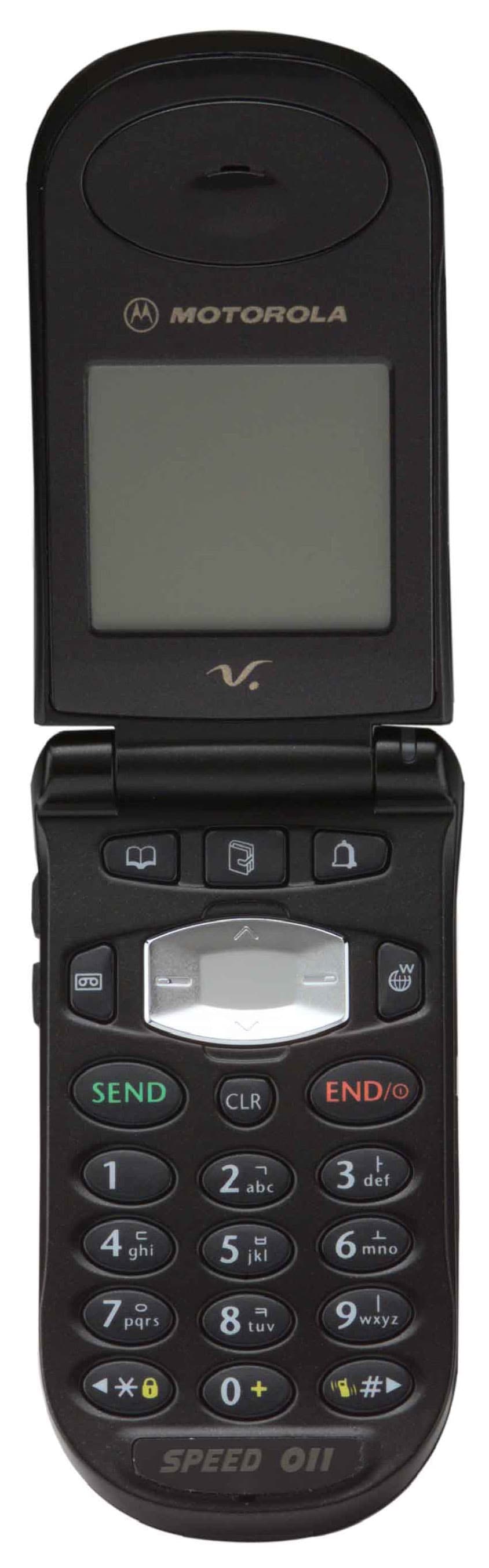
Click to zoom
Application Details
- Equipment Class
- TNE - Licensed Non-Broadcast Transmitter Held to Ear
- Date of Grant
- Aug 31, 2000
- Application Purpose
- Original Equipment
- Date of Application
- Jun 04, 2000
- Equipment Note
- Portable Cellular Transceiver
- Frequency Range
- 824.64000000 - 848.37000000
- Company
- Motorola Mobility LLC
- Country
- United States
Documents & Files
Document Text
Text extracted from the exhibit documents filed with the FCC. Open a document above to read the original.
Users Manual
APPLICANT: MOTOROLA, INC.FCC ID: IHDT5AG1 EXHIBIT 8 INSTRUCTION MANUAL A preliminary draft copy of the Users Manual follows: Welcome Thank you for Motorola-a global leader in communications technology. All Motorola celluler phones are designed and manufactured to meet Motorola’s exacting specifications and world-class quality standards. During development, our laboratory testing team took the durable “Motorola V” phone through its paces. They cooked it, dusted it, and dropped it - the phone still worked ! We are confident that the one you purchase will meet your own exacting standards. Thank you for choosing Motorola, and by all means, enjoy your “Motorola V” phone ! V8260 4 Exposure to Radio Frequency SignalsYou wireless handheld portable telephone is a low power radio transmitter and receiver.When it is ON, it receives and also sends out radio frequency (RF) signals.International Commission on Non-Ionizing Radiation Protection (ICNIRP) 1996Verband Deutscher Elektrotechniker(VDE) DIN-0848United States Federal Communications Commission, Radio Frequency ExposureGuidelines(1996)National Radiological Protection Board of the United Kingdom, GS 11, 1988American National Standards Institute(ANSI) IEEE. C95. 1-1992National Council on Radiation Protection and Measurements(NCRP). Report 86Department of Health and Welfare Canada. Safety Code 6. V8260 5 These standards were based on extensive scientific review. For example, over 120scientists, engineers, and physicians from universities, government health agencies, andindustry reviewed the available body of research to develop the updated ANSI Standard.The design of your phone complies with these standards when used normally.Antenna CareUse only the supplied or an approved replacement antenna. Unauthorized antennas,modifications, or attachment could damage the phone and may violate local agencyregulations.Phone Operation Normal Operation Hold the phone as you world any other telephone, with the antenna pointed up and overyour shoulder. Tips on Efficient Operation: Observe the following guidelines to operate your phone most efficienty. - Extend your antenna fully.- Do not touch the antenna unnecessarily when the phone is in use. Contact with the antenna affects call quality and may cause the phone to operate at ahigher power level otherwise needed. SAFETY INFORMATION V8260 6 BatteriesCAUTION ! All batteries can cause property damage, injury or burns if a conductivematerial, such as jewelry, keys or beaded chains, touches exposed terminals. The materialmay complete an electrical circuit and become quite hot. To protect against suchunwanted current drain, exercise car in handing and charged battery, particularly whenplacing it inside your pocket, purse or other container with metal objects. DrivingCheck the laws and regulations on the use of wireless telephones in the areas where youdrive. Always obey them. Observe the following guidelines when using your phone whiledriving. Give full attention to driving-driving safely is your first responsibility;Use hands-free phone operation, if available.Pull off the road and park before making or answering a call if driving conditions to require. V8260 7 VehiclesRF signals may affect improperly installed or inadequately shielded electronic systems inmotor vehicles. Check with the manufacturer of any equipment that has been added toyour vehicle.For Vehicles Equipped with an Air BagAn air bag inflates with great force. DO NOT place objects, including both installed orportable wireless equipment, in the area over the bag or in the air bag deployment area. Ifin-vehicle wireless equipment is improperly installed and the air bag inflates, serious injurycould result.Electronic DevicesMost modern electronic equipment is shielded from RF signals. However, certainelectronic equipment may not be shielded against the RF signals from your wirelessphone.PacemakersThe Health Industry Manufactures Association recommends that a minimum separation on V8260 8 six (6 ) inches be maintained between a handheld wireless phone and a pacemaker to avoid potential interference with the pacemaker. These recommendations are consistent with theindependent research by and recommendations of Wireless Technology Research.Person with pacemakers:- Should ALWAYS keep the phone more than six inches from their pacemaker when the phone is turned ON; - Should not carry the phone in a breast pocket;- Should use the ear opposite the pacemaker to minimize the potential for interference.- Should turn the phone OFF immediately if you have any reason to suspect that interference is taking place. Other medical devicesIf you use any other personal medical device, consult the manufacture of your device todetermine if it is adequately shielded from external RF energy. Your physician may be able toassist you in obtaining this information. V8260 9 Hearing AidsSome digital wireless phones may interfere with some hearing aids. In the event of suchinterference, you ,may want to consult your hearing aid manufacture to discuss alternatives.AircraftAirline regulations prohibit using your phone while in the air.Switch OFF your phone before boarding an aircraft.Potentially Explosive AtmospheresTurn your phone Off when in any area with a potentially explosive atmosphere, and obey allsigns and instruction. Sparks in such areas could cause an explosion or fire resulting inbodily injury or even death.Areas with a potentially explosive atmosphere are often, but not always, clearly marked. Theinclude fueling areas such as gasoline station; below deck on boats, fuel or chemicaltransfer or storage facilities; vehicles using liquefied petroleum has (such as propane orbutane); area where the air contains chemicals or particles, such as grain, dust, or metalpowders; and any other area where you would normally be advised to turn off your vehicleengine. V8260 10 BEFORE USE Confirm Components Name and Function of Each PartFunction of Each ButtonDescription of Display SymbolsHow to Use…
Text truncated - open the document above for the full version.
Attestation Statements
APPLICANT: MOTOROLAFCC ID: IHDT5AG1 EXHIBIT 2 STATEMENT OF CERTIFICATION June 1, 2000 Engineer- in-Charge Equipment Authorization Branch Federal Communications Commission I hereby certify that this transmit and receive equipment (FCC ID: IHDT5AG1) for dual-mode mobile station cellular use is capable of compliance with the July 1996 TIA/EIA IS-95-A, “Mobile Station -Base Station Compatibility Standard for Dual Mode Wide Band Spread Spectrum Cellular System”, and with OET bulletin No. 53, “Cellular System Mobile Station - Land Station Compatibility Specification”. Signature: (signed________( signed)___________ NAME:Anthony E. Akers DATE:June 1, 2000 POSITION:Director of Engineering Motorola, Inc. I hereby certify that the above application was prepared under my direction and that to the best of my knowledge and belief, the facts set forth in the application and accompanying technical data are true and correct. Signature: (signed________( signed)___________ NAME:Anthony E. Akers DATE:June 1, 2000 POSITION:Director of Engineering Motorola, Inc.
Cover Letter(s)
APPLICANT: MOTOROLAFCC ID: IHDT5AG1 Exhibit 13 June 5, 2000 CONFIDENTIALITY REQUEST CONTAINED WITHIN Federal Communications Commission Authorization and Evaluation Division 7435 Oakland Mills Road Columbia, Maryland 21046 Re: Application for Cellular Transceiver Certification Gentlemen: Application: Motorola, Inc., Personal Communications Sector, 600 N. U.S. Highway 45, Libertyville, Illinois 60048-1286 herein submits: Application for Equipment Authorization (FCC Form 731-October 1992 with integrated Fee Processing Form, Fee Codes EFT and EBC), application fee in the amount of $610, and Exhibits, for Type Acceptance of a Cellular Transceiver; FCC ID: IHDT5ZU1. Motorola is also the manufacturer of this equipment. Confidentiality: Pursuant to Section 0.459 of the Commission's rules (CFR 47), Motorola requests confidentiality for portions of the material contained in this application and that the identified material be withheld from public inspection following the grant of this authorization. This material contains Motorola's trade secrets and confidential information that Motorola does not customarily release to the public and which is otherwise not generally available to the public. Confidentiality is requested for the following exhibits: • Exhibit 4 Block Diagrams • Exhibit 5 Schematics • Exhibit 12 Operational Description Description: This equipment has the capability to operate only in the Digital CDMA standard in the 800 MHz cellular band, as outlined in EIA/TIA IS-95-A "Mobile Station – Base Station Compatibility Standard for Dual-Mode Wideband Spread Spectrum Cellular System”. Technical details for this alternate cellular technology (permitted under the cellular service option provisions in Section 22.901(d) of the Commission's rules) related to Type Acceptance of this equipment, as noted in paragraphs 31 and 32 of the Report and Order in FCC GEN. Docket No. 87-390, are detailed in Exhibit 12. Contact Information: Please contact me by telephone at (847) 523-6167, or by e-mail ([email protected]), if there are any further questions or additional information needed concerning this filing. Regards, Andrew J. Bachler FCC Liaison Cellular Subscriber Sector 600 N. U.S. Highway 45 Libertyville, IL 60048-5343
External Photos
APPLICANT: MOTOROLA, INC. FCC ID: IHDT5AG1 EXHIBIT 3 Front View Rear View with Battery Removed to Show Equipment ID Label
ID Label/Location Info
APPLICANT: MOTOROLAFCC ID: IHDT5AG1 EXHIBIT 1 FCC IDENTIFICATION (NAMEPLATE) INFORMATION The FCC label shown is the label that will appear on the radio when in production. It will be placed on the outside of the radio telephone. (refer to exhibit 3). FCC ID: IHDT5AG1
Internal Photos
APPLICANT: MOTOROLA, INC. FCC ID: IHDT5AG1 EXHIBIT 9 Front View Rear View
Parts List/Tune Up Info
APPLICANT: MOTOROLAFCC ID: IHDT5AG1 EXHIBIT 10 TRANSMITTER ADJUSTMENTS/TUNE-UP PROCEDURE There are no user accessible adjustments or tuning in this portable cellular transceiver. All necessary adjustments and tuning are performed during manufacture of the product. Any adjustments or tuning for service or repair is done by connecting the radio set to the special test equipment capable of communicating with it over a Motorola Proprietary Cable.
RF Exposure Info
May 8, 2000 SAR Test Report for Motorola portable cellular phone (FCC ID IHDT5AG1). Prepared by: Paul Moller, Principal Staff Engineer Motorola Personal Communications Sector Product Safety Laboratory Libertyville, Illinois Contents 1) Introduction 2) Applicable Regulations 3) Description of Test Sample 4) Description of Motorola SAR Test Facility 5) Test Sample Conditions 6) Method of Measurement 7) Measurement Uncertainty 8) SAR Test Results 9) SAR in the hand measurements 10) Body Worn Configuration 11) Battery Options 12) Summary Appendix A: Included data from Against the Phantom Head Appendix B: Included data from Body Worn Configuration Appendix C: Printout from the Dasy™ measurement system validation test P P a a g g e e 2 2 1. Introduction The Motorola Personal Communications Sector Product Safety Laboratory has performed measurements of the maximum potential exposure to the user of portable cellular phone FCC ID IHDT5AG1. The Specific Absorption Rate (SAR) of this product was measured. This report details the test setup and equipment as well as the results of those tests. 2. Applicable Regulations Federal Communications Commission rule §2.1093(d)(2), the ANSI/IEEE C95.1 1992 and the NCRP Report Number 86 specify the maximum exposure limit of 1.6 W/kg as averaged over any 1 gram of tissue for portable devices being used within 20cm of the user in the uncontrolled environment. 3. Description of Test Sample A prototype unit serial number 450002 was measured. This unit is identical in physical construction, maximum radiated power levels and antenna structure to units that will be in production. It transmits in the frequency range of 824.04 to 848.97 MHz using CDMA mode. The unit was tested at its maximum transmitter power. The unit is equipped with a telescoping antenna that serves as both a receive and transmit antenna. The antenna has a retracted and an extended operating position as shown in figures 1 and 2 respectively. Figure 1. Showing Retracted Antenna Figure 2. Showing Extended Antenna P P a a g g e e 3 3 Figure 3 shows the test unit as it is placed onto the Motorola phantom. For the purposes of the actual SAR tests the Motorola phantom head is tilted on its side by 90 degrees so that a vertically oriented measurement probe can easily scan an area where the phone is in close contact with the phantom and the SAR will be the highest. Figure 3. Phone against side of Phantom Head. 4. SAR Test Facility The Motorola test facility utilized for the SAR testing of this product is the Personal Communications Sector Product Safety Laboratory, in Libertyville Illinois. The laboratory utilizes a Dosimetric Assessment System (Dasy™) SAR measurement system manufactured by Schmid & Partner Engineering AG (SPEAG™), of Zurich Switzerland. This system utilizes a computer controlled six axis robot to move a measurement probe to measure the SAR. A photo of the Dasy™ system with the Motorola phantom is shown in figure 4. Probe serial number 1398 was used for the measurements. It was calibrated at SPEAG™, and has a calibration date October P P a a g g e e 4 4 28, 1999. Dipole Validation Kit type D900V2, serial number 063 was used to validate the system accuracy. The validation SAR value is 10.0 mW/g normalized to 1 Watt, and the Dasy™ system used for the test phone measured 9.56 mW/g normalized to 1 Watt. This is within the required accuracy, and thus the measured SAR values are considered correct. See appendix C for printout of the validation test from the Dasy™ measurement system. The measurement methodology is described in IEEE Transactions on Vehicular Technology, vol. 44, no. 3, August 1995, titled Electromagnetic Energy Exposure of Simulated users of Portable Cellular Telephones. The Dasy™ system is operated per the instructions in the Dasy™ Users Manual. The entire manual is available directly from SPEAG™. Figure 4. Dasy™ System 5. Test Sample Conditions For the purposes of these tests the subject phone was positioned on the measurement phantom per the instructions in the Motorola users manual for the subject phone. The position used for the tests is the 3-point contact position. In this position the test sample contacts the phantom’s ear and cheek and is positioned with a repeatability of better than ±6%. Since the antenna is not located on the center of the phone, the SAR was measured with the phone on both the left and P P a a g g e e 5 5 right side talk positions (See figure 3). Due to the construction of the phone, the base of the antenna is 18 mm away from the phantom for the right side head, which is the closest. For the purposes of the CDMA mode tests, the unit is placed in a phone call using an HP8924 and is commanded to the highest possible power by means of the “always up” command. The phone is then placed in the SAR measurement system with a fully charged battery. At the end of each test the Dasy™ system measures the drift of the SAR at a fixed point in the phantom so as to ensure that the test sample has not changed in transmitter power. For the purposes of these tests, the transmitter was operated at the highest transmitter output and with the phone and module on both left and right side talk positions. 6. Method of Measurement The system is instructed to scan as much of the face of the phone as is in close proximity to the phantom. Using the information gained about the general region of highest SAR, the system then automatically scans a smaller area centered around the location of peak spatial SAR. During this scan the system automatically measures the fall off of electric field strength as the measurement probe is moved away from the inner surface of the phantom in the direction of the local normal to the phantom surface. Using appropriate probe calibration techniques, the SAR in 1 gram of phantom tissue is then calculated. The phantom head was filled with a liquid having relative dielectric constant equal to 50.59 and conductivity equal to 0.89 S/m. This mixture is a good …
Text truncated - open the document above for the full version.
RF Exposure Info
1 2 Compliments Thanks in deed for purchasing this cellular phone of Motorola which takes pride in its world-best radio communication technology. All of the Motorola cellular communication equipment are designed and manufactured in compliance with the in-house strict standards and international standards, and especially, they are subjected to stringent quality tests in connection with temperature, humidity, impact, dust, vibration, and drop before being released. We assure you that this V8260 phone manufactured through these processes gives you high quality satisfaction. Thank you again for selecting our products, in the hope that you would succeed in your business with your V8260. ? Any content of this manual and any function of this product are subject to change according to situation. ? We suggest that you set your phone to vibration mode at a public place in order to observe right manners in using the phone. EVRC(Enhanced Variable Rate Codec) adopted This product adopts EVRC technology to enhance call quality that reduces noises and gives maximum vividness to the original sound. 3 Each digital wireless phone manufactured and supplied by Motorola has its own ESN(Electronics Serial Number). Removal or change of this ESN, or an attempt to reproduce and enter another ESN shall be deemed an illegal act. Any person who commits such an illegal act shall be sentenced to three or less years' penal servitude or fined 10 million or less won pursuant to the related civil laws(Article 4 of Radio Wave Act, Article 4 of Telecommunications Enterprise Act, and Article 347 of the Criminal Law Act). In addition, such an illegal act may damage the software built in the phone, with the result that the phone cannot be used any longer. Thus, customers are required to use care not to incur any damage due to such an illegal act. Especially, once such an illegal act is identified, both the free and paid services warranted by Motorola are rejected. Precautions ¦ Do not lend your own phone to other person inadvertently. ¦ For repairs or other services, contact our designated service center. ¦ If your phone has got lost or stolen, immediately report to the relevant telecommunications service provider. ? This product should not be added with any separate equipment that may cause an alteration to its original performance as described on type registration. Prohibition of illegal modification of ESN 4 Safety Information for Digital Wireless Phone Exposure to radio frequency signal Your digital wireless phone is a power radio transmitter and receiver. When it is ON, it receives and also sends out high radio frequency(RF) energy. International agencies have set standards and recommendations for the protection of public exposure to RF energy. iANSI IEEE.C95.1 (1992)* iNCRP Report (1986)* iICNIRP (1996)* iVDE DIN-0848* United States Federal Commission, Radio Frequency Exposure Guidelines (1996) National Radiological Protection Board of the United Kingdom, GS 11, 1988 Department of Health and Welfare Canada, Safety Code 6 *American National Standards Institute: National Council on Radiation Protection and Measurements: International Commission Non-Ionizing Radiation Protection: Verband Deutscher Elektotechniker 5 These standards are based on extensive scientific review over a long period of time. For instance, over 120 scientists, engineers, physicians from universities, government health agencies, and industry reviewed the available body of research to develop the ANSI Standard(C95.1). The design of your phone complies with the FCC guidelines (and those standards). For additional information concerning exposure to radio frequency signals, see the statement by the FDA at the end of this user guide. To maintain compliance with FCC RF exposure guidelines, if you wear a handset on your body, use the Motorola-supplied or approved carrying case, holster, or other body-worn accessory. If you do not use a body-worn accessory, ensure the antenna is at least one inch (2.5 centimeters) from your body when transmitting. Use of non-Motorola accessories may violate FCC RF exposure guidelines. Antenna Use only the antenna authorized by Motorola. Using an unauthorized antenna may damage your phone, which rejects the free services offered by Motorola. Normal Position in Operation Hold your phone as when doing to the general telephone. Place the antenna straight over your shoulder. Effective Phone Operation Fully extend the antenna. Hold your phone as when doing to the general telephone, with the antenna placed straight over your shoulder. Speak distinctly to your phone with your mouth placed near the transmitter.
Test Report
APPLICANT: MOTOROLAFCC ID: IHDT5AG1 EXHIBIT 6 MEASUREMENT DATA Submitted Measure Data Index ExhibitDescription 6ARF Power Output – Measured Data (Conducted and Radiated) 6BOccupied Bandwidth in the CDMA Digital Mode 6CConducted Spurious and Harmonic Emission 6DRadiated Spurious and Harmonic Emission 6EFrequency Change vs. Temperature 6FFrequency Change vs. Supply Voltage APPLICANT: MOTOROLAFCC ID: IHDT5AG1 EXHIBIT 6A MEASUREMENT DATA RF Power Output Data The input supply to the transmitter is set at 3.8 volts. The RF power output was measured with the indicated voltage and current applied into the final RF amplifying device. Conducted Power The values measured for RF Output, DC Current and RF Input Power are all average values which reflect a 100% transmit duty cycle in CDMA operation. The maximum RF output power is restricted to the 24.2 dBm. The RF output power is measured at the mobile station’s antenna port. Measured RF Output Power: 0.263 W (24.2 dBm) Measured DC Voltage: 3.8 V Measured DC Current: 635 mA Measured RF input: 0.63mW (-2 dBm) Effective Radiated Power: Since the phone is intended for use with a provided antenna (and non-standard RF connector), ERP is measured. The dipole antenna substitution method was used. The result indicated is the maximum ERP found over the channels and radio orientations tested. The maximum was found in transmitting mode with the antenna in the extended position. The input supply to the transmitter was set at 3.8 Volts Maximum EIRP is 0. 218 W (23.38 dBm) in CDMA mode. Maximum Effective Radiated Power (Relative to Half-Wavelength Dipole): 0.135 W (21.28 dBm) APPLICANT: MOTOROLAFCC ID: IHDT5AG1 EXHIBIT 6B Occupied Bandwidth in the CDMA Digital Mode 1. Spurious emission level : Modulate the transmitter with OQPSK modulation, using pseudo random data. Obtain image on spectrum analyzer. (Refer to IS98A, 10.4.2.1) Deviation of the Carrier with OQPSK Modulation Horizontal Scale = 0.62 MHz/Division Vertical Scale = 10 dB/Division(Attenuation) Resolution Bandwidth =30 kHz Power Level = 0.263 W (24.2 dBm)(Average power in transmitter) Measured Data: Comments: Spurious emission level for frequency offset at greater than 885 kHz shall be at least –42 dBc/30kHz and level for frequency offset at greater than 1.98MHz shall be at least –54 dBc/30kHz. APPLICANT: MOTOROLAFCC ID: IHDT5AG1 EXHIBIT 6B 2. Occupied Bandwidth should be less than 1.32 MHz. Deviation of the Carrier with OQPSK Modulation Horizontal Scale = 0.3 MHz/Division Vertical Scale = 10 dB/Division(Attenuation) Resolution Bandwidth =30 kHz Occupied BW [99.00%] = 1.275 MHz Measured Data: APPLICANT: MOTOROLAFCC ID: IHDT5AG1 EXHIBIT 6C Conducted Spurious and Harmonic Emission 1. Transmitter Conducted Spurious Emission Carrier Power: 0.065 mW (-12 dBm) Carrier Frequency: low(ch#=1011), mid(ch#=363), high(ch#=779) in 824.04 to 848.97 MHz * Each reported emission reflects the highest absolute level found among all power levels, channels, and power amplifier configuration tested. * All emissions not reported are more 20 dB below the FCC specification. * Spectrum was searched from 30 kHz to the 10 th harmonic of the transmitter. ** Spurious Emission Limits when transmitting in CDMA mode (IS-98A, 10.5.1) For Frequency Offset ∆f, with∆f Greater than 885.0 kHzGreater than 1.98 MHz Spurious Emission levels shall be less than either (a), or both (b) and (c) (a) –42dBc/30 kHz(a) –54dBc/30 kHz (b) –60dBm/30 kHz (c) –54dBm/1.23MHz (b) –60dBm/30 kHz (c) –54dBm/1.23MHz Transmitter Conducted Spurious Emissions -10-8-6-4-20246810122345678910 Frequency Spurious Level (dBm) Spec Margin = -37.8 dBc PTX=-12 dBm Frequency from Carrier (MHz)Harmonics SPEC. Limit = -49.8 dBm APPLICANT: MOTOROLAFCC ID: IHDT5AG1 EXHIBIT 6D Radiated Spurious and Harmonic Emission -6-4-202462345678 frequency from carrierfrequencyharmonic of carrier specification limit :43 + 10 log (carrier power) = -13.00 dBm Transmitter conducted spurious emissions 9 10 Transmitter @ 25.0 dbm -33 -33 -37 -38 ( in dbm) APPLICANT: MOTOROLAFCC ID: IHDT5AG1 EXHIBIT 6E Frequency Change vs. Temperature * Each reported frequency deviation reflects the highest absolute levels found among several condition. Freq. Vs. Temperature Temperature [Deg.] Freq. Variation [Hz] APPLICANT: MOTOROLAFCC ID: IHDT5AG1 EXHIBIT 6F Frequency Change vs. Voltage * Each reported frequency deviation reflects the highest absolute levels found among several condition. 3.6V Lower Limit: -300Hz Freq. Variation vs. Voltage Voltage [V] Freq. Variation [Hz]
Test Report
APPLICANT: MOTOROLAFCC ID: IHDT5AG1 EXHIBIT 6L MEASUREMENT TECHNIQUES Measurements Required: Conducted Spurious and Harmonic Emissions at Antenna Terminals Graph attached EXHIBIT 6C Definition- (as used herein) Spurious radiations are the radio frequency voltages or power generated within the equipment and appearing at the equipment’s output terminals when properly loaded with its characteristic non-radiating artificial load. Minimum Standard- The magnitude of each spurious and harmonic emission that can be detected when the equipment is operated under the conditions specified in the alignment procedure, EXHIBIT 10, shall be attenuated 43 dB below the mean power output. In the range of frequencies between 869.04 MHz and 893.97 MHz, no spur shall exceed –80 dBm. Method of Measurement- The transmitter was modulated using pseudo random data. The spectrum was scanned from the lowest frequency generated in the equipment to the tenth harmonic of the carrier. The level of the carrier and various conducted spurious and harmonic frequencies shall be measured by means of a calibrated receiving system used to compare the output of the transmitter with that of a standard signal generator at the spurious frequency. Measurements Required: Radiated Spurious and harmonic Radiation Graph attached EXHIBIT 6D Definition: Radiated spurious and harmonic emissions are frequencies from the equipment when loaded into a non-radiating load on a frequency or frequencies which are outside an occupied band sufficient to insure transmission of information of required quality for the class of communications desired. The reduction in the level of these spurious emissions will not effect the quality of the information being transmitted. Minimum standard- Radiated spurious emissions shall be attenuated 43 dB below the mean power output. In the range of frequencies between 869.04 MHz and 893.97 MHz, no spur shall exceed –80 dBm. Method of Measurement: DESCRIPTION OF MEASUREMENT FACILITIES Site on File With the FCC ID Number: 31040/SIT “ The site referenced above has been found to comply with the test site criteria found in ANSI C63.4-1992 and 47CFR Section 2.948.” APPLICANT: MOTOROLAFCC ID: IHDT5AG1 EXHIBIT 6L INTRODUCTION A series of Radiated Emissions tests were performed on a sample model of the Motorola CDMA (Abalone) Cellular Telephone. These tests were performed using the test procedures outlined in ANSI C63.4-1992 for intentional radiators, as called for in section 2.1033 for a type accepted device, and in accordance with the limits set forth in FCC Part 15.209 and 22.917e. Tests of conducted emissions were also performed in order to verify compliance with the limits set forth in part 22.917e and called out in section 2.1033 for a type accepted device. PURPOSE The above mentioned tests were performed in order to determine the compliance of the test sample with limits contained in various provisions of Title 47 CFR, including: 2.105115.209 2.105322.917 All radiated emissions tests were performed to measure the emissions in the frequency bands described by the above sections, and to determine whether said emissions are below the limits established by the above sections. These tests were performed in accordance with the procedure described in the American National Standard for methods of measurement of Radio-Noise Emissions from Low-Voltage Electrical and Electronic Equipment in the Range of 9 kHz to 40 GHz (ANSI C63.4-1992). Another document used as reference for the EMI receiver specification was the International Special Committee on Radio Interference (CISPR) number 16-1 (1993). RADIATED EMISSIONS TEST SETUP The test sample was operated within the 3 meter Semi-Anechoic, FCC listed chamber located at L.S. Compliance in Cedarburg, WI. The sample was placed on an 80cm high wooden table, which was centered on the flush-mounted 2m diameter metal turntable. The test sample was operated on its internal rechargeable battery. The test sample was configured to run in a continuous transmit mode , with a 50 ohm dummy load attached to the antenna port, during the Radiated measurements. The test sample was set to operate on one of three standard channels within the Cellular frequency assignment: one at the low end of the band (1013), one in the middle of the band (384) and one near the top of the band(779). RADIATED EMISSION TEST PROCEDURE The fundamental and spurious (harmonic) emissions of the transmitter were tested for compliance to Title 47 CFR, FCC Part 22.917e limits for transmitters in the Public mobile services, and were also compared with the general l…
Text truncated - open the document above for the full version.
Contact Information
Applicant
Jeff Narducci(Director Product Compliance)
Technical Specifications
| # | Rule Parts | Frequency Range | Power Output | Emission | Tolerance |
|---|---|---|---|---|---|
| 1 | 22.901(d) | 824.64 MHz - 848.37 MHz | 140.00 mW | 1M25F9W | 300.0000000000 Hz |
Other Applications from Motorola Mobility LLC
IHDT56AW9
May 12, 2026Smart Watch
Equipment Class
NII - Unlicensed National Information Infrastructure TXIHDT56AW5
Apr 08, 2026Mobile Cellular Phone
Equipment Class
DTS - Digital Transmission SystemIHDT56AW6
Mar 18, 2026Smart Watch
Equipment Class
JBP - Part 15 Class B Computing Device PeripheralIHDT56AX4
Mar 17, 2026Mobile Cellular Phone
Equipment Class
PCE - PCS Licensed Transmitter held to earIHDT56AW3
Mar 03, 2026Mobile Cellular Phone
Equipment Class
6XD - 15E 6 GHz Low Power Indoor Client