IHDT5AT1Cellular Mobile Transceiver
Motorola Mobility LLC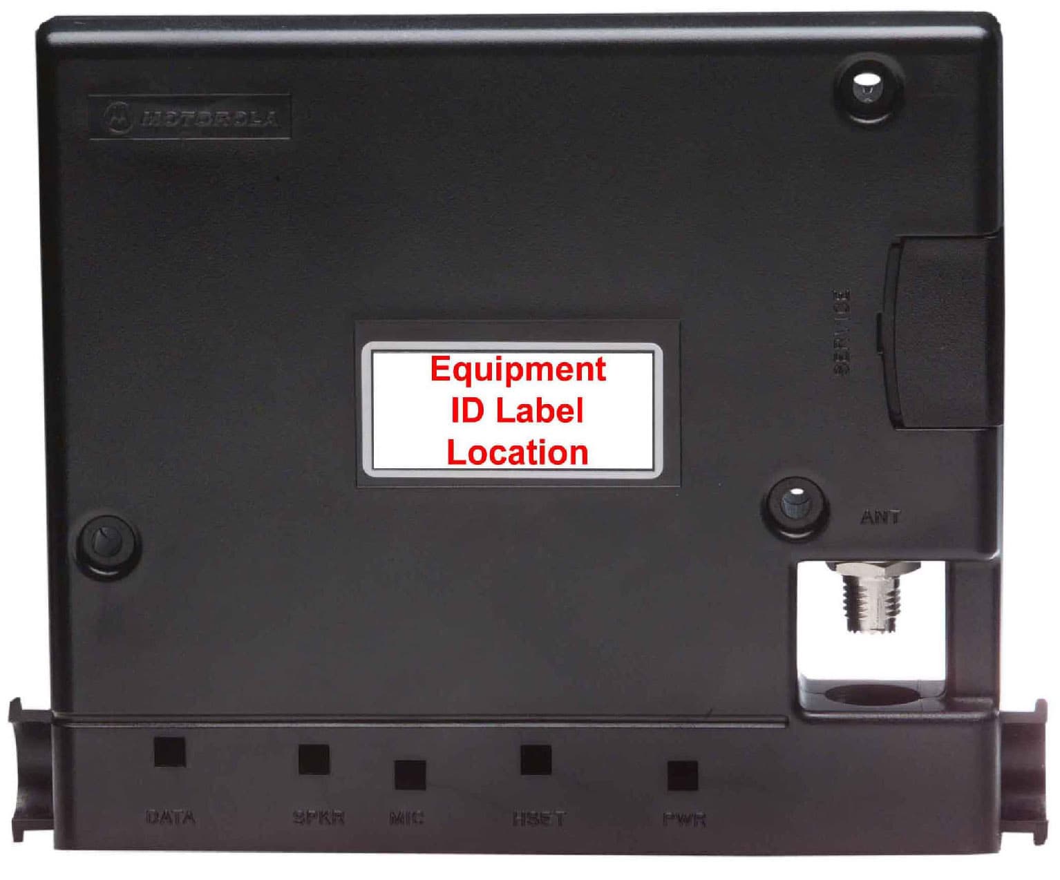
Click to zoom
Application Details
- Equipment Class
- TNB - Licensed Non-Broadcast Station Transmitter
- Date of Grant
- Sep 10, 2000
- Application Purpose
- Original Equipment
- Date of Application
- Jun 08, 2000
- Equipment Note
- Cellular Mobile Transceiver
- Frequency Range
- 824.07000000 - 848.31000000
- Company
- Motorola Mobility LLC
- Country
- United States
Documents & Files
Document Text
Text extracted from the exhibit documents filed with the FCC. Open a document above to read the original.
Users Manual
APPLICANT: MOTOROLA INC.FCC ID: IHDT5AT1 EXHIBIT 8 USERS MANUAL INFORMATION 1. The following antenna installation guidelines will be shipped with each product: ANTENNA INSTALLATION GUIDELINES IMPORTANT: To meet the FCC’s RF Exposure guidelines, the antenna must be installed so there is at least 20 cm of separation between the occupants of the vehicle and the antenna. 2. A draft copy of the users manual follows: Note: A draft of the user manual is in Hebrew language, since the only customer is Israeli. The following Motorola standard Safety Information is included in the manual. Safety Information (Mobile Version) IMPORTANT: Read this information before using your wireless mobile phone. Exposure to Radio Frequency Signals Your wireless mobile telephone is a low power radio transmitter and receiver. When it is ON, it receives and also sends out radio frequency (RF) signals. International agencies have set standards and recommendations for the protection of public exposure to RF electromagnetic energy. • International Commission on Non-Ionizing Radiation Protection (ICNIRP)1996 • Verband Deutscher Elektrotechniker (VDE) DIN-0848 • United States Federal Communications Commission, Radio Frequency Exposure Guidelines (1996) • National Radiological Protection Board of the United Kingdom, GS 11, 1988 • American National Standards Institute (ANSI) IEEE. C95. 1-1992 • National Council on Radiation Protection and Measurements (NCRP). Report 86 • Ministry of Health (Canada), Safety Code 6 These standards are based on extensive scientific review. For example, over 120 scientists, engineers, and physicians from universities, government health agencies, and industry reviewed the available body of research to develop the updated ANSI standard. The design of your phone complies with these standards when used as described under "Phone Operation." APPLICANT: MOTOROLA INC.FCC ID: IHDT5AT1 EXHIBIT 8 Antenna Care Use only the supplied or an approved replacement antenna. Unauthorized antennas, modifications, or attachments could damage the phone and may violate local agency regulations. Phone Operation Do not operate your mobile telephone when a person is within 8 inches (20 centimeters) of the antenna. A person or object within 8 inches (20 centimeters) of the antenna could impair call quality and may cause the phone to operate at a higher power level than necessary and expose that person to RF energy in excess of that established by the FCC RF Exposure Guidelines. Driving Check the laws and regulations on the use of wireless telephones in the areas where you drive. Always obey them. Observe the following guidelines when using your phone while driving. • Give full attention to driving--driving safely is your first responsibility. • Use hands-free phone operation, if available. • Pull off the road and park before making or answering a call if driving conditions so require. Electronic Devices Most modern electronic equipment is shielded from RF signals. However, certain equipment may not be shielded against the RF signals from your wireless phone. Pacemakers The Health Industry Manufacturers Association recommends that a minimum separation of 6 inches (15 centimeters) be maintained between a wireless phone's antenna and a pacemaker to avoid potential interference with the pacemaker. These recommendations are consistent with the independent research by and recommendations of Wireless Technology Research. Persons with pacemakers: • should ALWAYS keep the phone more than 6 inches (15 centimeters) from their pacemaker when the phone is turned ON • should turn the phone OFF immediately if you have any reason to suspect that interference is taking place Other Medical Devices If you use any other personal medical device, consult the manufacturer of your device to determine if it is adequately shielded from external RF energy. Your physician may be able to assist you in obtaining this information. Turn your phone OFF in health care facilities when any regulations posted in these areas instruct you to do so. Hospitals or health care facilities may be using equipment that could be sensitive to external RF energy. Vehicles RF signals may affect improperly installed or inadequately shielded electronic systems in motor vehicles. Check with the manufacturer or its representative regarding your vehicle. You should also consult the manufacturer of any equipment that has been added to your vehicle. Posted Facilities Turn your phone OFF in any facility where posted notices so require. Blasting Areas To avoid interfering with blasting operations, turn your phone OFF when in a "blasting area" or in areas posted: "Turn off two-way radios." Obey all signs and instructions. APPLICANT: MOTOROLA INC.FCC ID: IHDT5AT1 EXHIBIT 8 Aircraft (Carry Phones) If you are using your mobile phone as a carry phone, switch OFF your phone before boarding an aircraft. Airline regulations prohibit using your phone while in the air. Check and comply with the policy of your airline regarding the use of your phone while the aircraft is on the ground. Blasting Areas To avoid interfering with blasting operations, turn your phone OFF when in a "blasting area" or in areas posted: "Turn off two-way radio." Obey all signs and instructions. Potentially Explosive Atmospheres Turn your phone OFF, do not remove your battery when you are in any area with a potentially explosive atmosphere, and obey all signs and instructions. Sparks from your battery in such areas could cause an explosion or fire resulting in bodily injury or even death. Areas with a potentially explosive atmosphere are often but not always clearly marked. They include: fueling areas such as gasoline stations; below deck on boats; fuel or chemical transfer or storage facilities; areas where fuel odors are present (for example, if a gas/propane leak occurs in a car or home); areas where the air contains chemicals or particles, such as grain, dust, or metal powders; and any other area where you normall…
Text truncated - open the document above for the full version.
Users Manual
APPLICANT: MOTOROLA INC.FCC ID: IHDT5AT1 EXHIBIT 8 Supplement 9-8-00 USERS MANUAL INFORMATION 1. A preliminary draft copy of the users manual follows: Note: This preliminary English version of the manual does not contain graphics. It is text only. The RF safety and antenna installation sections are on page 8. CMR2100 UM.doc1/78 MOTOROLA CMR 2100 – General View CMR2100 UM.doc2/78 Welcome! Thank you for choosing MOTOROLA / a global leader in communications technology. All MOTOROLA cellular phones are designed and manufactured to meet MOTOROLA's exacting specifications and world-class quality standards. The CMR 2100 is no exception to this rule. This car phone successfully passed reliability trials, such as temperature, humidity, vibration, dust, shaking, and dropping. With the CMR 2100 car phone you are guaranteed a superior product. Always at your service MOTOROLA CMR2100 UM.doc3/78 Contents Introduction What's new? Major advantages Safe and efficient operation The Basics General view Using the phone Using the smart button Reading the indicators Placing and ending calls Receiving calls Redialing numbers Basic tone controls Your phone and its shortcuts Using memory Making the most of memory Storing names and phone numbers Recalling from memory Scratch pad memory Advanced storage Using calling cards The menu Introducing the menu features The internal phonebook Recalling using the memory Phonebook status Editing a memory location Displaying the user's phone number Preference for name/number Call timers Viewing the individual timer Viewing the resettable timer Viewing the cumulative timer Resetting the timer One minute audible timer Programmable timers Tone controls Silent mode Selecting a ringer style Reminder tones setup Lock/security features Auto lock Secure options submenu Authentication – personal identification code Phone options Feature review Call options submenu Multi key answer Automatic answer CMR2100 UM.doc4/78 Instant redial Display options submenu Changing the language Changing the banner Backlighting Auto hyphen 24-hour clock Mini Browser options Launching the Mini Browser Power up mode Confirm at start-up System options submenu Displaying the system ID Using messaging Access to messages Caller IDs Caller ID options Voice mail options Reading your messages Using the Mini Browser Launching Mini Browser navigation Using bookmarks Using the Mini Browser Using data features Appendices Accompanying accessories Warranty CMR2100 UM.doc5/78 What's new? The CMR 2100 car phone is an innovative product incorporating the CDMA advanced digital technology, which offers the following new features: Mini Browser WAP The browser permits fast and easy access to personal information services* such as weather reports, sports results, traffic reports, etc. Expanded phonebook Your phone contains 99 memory locations, in each of which you can store up to 4 phone numbers. Data transmission support system Your phone supports a data transmission system*, using data transfer software such as Hyper Terminal, and a data cable. This feature permits data transmission and synchronization between your phone, a desktop computer and a laptop computer. Real time clock The digital CDMA system currently updates in real time the clock appearing in the display. Personal banner You can create your own message banner (up to 12 characters long) by using the Change Banner feature, which will be displayed by the phone when it is idle (see page __). Messages menu Viewing the call ID*, using voice mail messages*, and reading test messages* is very easy with the aid of the special messages key [**]. (see page __). * Contact your Service Provider for availability. Caller ID name If Caller ID* is active on your phone you will be able to see who is calling before you answer. The display will show your caller's name if it is in you phonebook. Large display screen Very wide alpha numeric LCD display, with 4 rows of text and 2 rows of menu indicators. The smart button Using the smart button you can do the following: • Operate the phone with one hand CMR2100 UM.doc6/78 • Store information • Recall a number, dial a number, end a call, etc. Updating the phonebook from a computer If the MOTOROLA data connecting kit* is installed in your car you can transfer names and phone numbers between your PC and the CMR 2100 (in both directions), using the Phone Synchronizer software. * Contact your Service Provider for availability. CMR2100 UM.doc7/78 Major features The CMR 2100, which is one of the most sophisticated cellular phones currently available, offers you a range of features suited to your life style. This sophisticated digital phone can help you to: • Redial automatically if the number if engaged • Receive a call discreetly through the earpiece • Dial easily and quickly using the Turbo Dial keys • Use browser services which provide fast access to personal information services • Connect to the data kit which provides options of sending data, etc. • Use the integral speakerphone kit • Recall phone numbers using the internal phonebook • Monitor length of calls using a range of call counters • Adjust the ringer style to the type you wish • Large, easy to use keypad in Hebrew and English • Large, easy-to-read display As you get to know the CMR 2100 you will discover more and more important and easy-to-use features. CMR2100 UM.doc8/78 Safety Information IMPORTANT: Read this information before using your wireless mobile phone. Exposure to Radio Frequency Signals Your wireless mobile telephone is a low power radio transmitter and receiver. When it is ON, it receives and also sends out radio frequency (RF) signals. International agencies have set standards and recommendations for the protection of public exposure to RF electromagnetic energy. • International Commission on Non-Ionizing Radiation Protection (ICNIRP)1996 • Verband Deutscher Elektrotechniker (VDE) DIN-0848 • United States Federal Communications Commission, Radio Frequency Exposure …
Text truncated - open the document above for the full version.
Attestation Statements
APPLICANT: MOTOROLA, INC.FCC ID : IHDT5AT1 EXHIBIT 2A SPECIFICATION COMPLIANCE STATEMENT Engineer-in-Charge Equipment Authorization Branch Federal Communications Commission We hereby certify that this transmit and receive equipment (FCC ID: IHDT5AT1) for single band 800Mhz, CDMA cellular mobile radio use is capable of CDMA compliance with the TIA/EIA-95-B Mobile Station-Base Station Compatibility Standards for Dual- Mode Spread Spectrum Systems, December 1998. (Signed – Yossi Lovton) Yossi Lovton Engineering Section Manager Motorola Israel – Advanced Systems And product Division (Signed – David Termin ) David Termin Mobile CDMA Project Manager Motorola Israel – Advanced Systems And product Division APPLICANT: MOTOROLA, INC.FCC ID : IHDT5AT1 EXHIBIT 2B STATEMENT OF CERTIFICATION The technical data supplied with this application, having been taken under my supervision is hereby duly certified. The following is a statement of my qualifications: PRACTICAL ENGNEER 1985 ORT University 15 Years Cellular Design Experience SIGNATURE: (signed) Yossi Lovton NAME: Yossi Lovton DATE: 12/6/2000 POSITION: Engineering Section Manager I hereby certify that the above application was prepared under my direction and that to the best of my knowledge and belief, the facts set forth in the application and accompanying technical data are true and correct. BSC ENGNEER 1994 Ariel University 5 Years Cellular Design Experience SIGNATURE: (signed) David Termin NAME: David Termin DATE: 12/6/2000 POSITION: Mobile CDMA Project Manager
External Photos
APPLICANT: MOTOROLA, INC. FCC ID: IHDT5AT1 EXHIBIT 3 Front (Connector) View Top (Label) View Bottom View
ID Label/Location Info
APPLICANT: MOTOROLA INC.FCC ID: IHDT5AT1 EXHIBIT 1 FCC IDENTIFICATION (NAMEPLATE) INFORMATION MOTOROLA INC. FCC ID: IHDT5AT1 The FCC Label shown is the label that will appear on the radio when in production. It will be placed on the outside of the radio box. ( Refer to exhibit 3 ).
Internal Photos
Exhibit 9A APPLICANT: MOTOROLA, INC. TRANSCEIVER TYPE: IHDT5AT1 Transceiver Board Top Side (Shields Removed) Bottom Side (Shields Removed) Exhibit 9B APPLICANT: MOTOROLA, INC. TRANSCEIVER TYPE: IHDT5AT1 Internal View Interface Board Transceiver Board
Parts List/Tune Up Info
APPLICANT: MOTOROLA INC.FCC ID: IHDT5AT1 EXHIBIT 10 TRANSCEIVER ADJUSTMENTS/TUNE-UP PROCEDURE There are no user adjustments or tuning in this mobile cellular transceiver.
RF Exposure Info
1 1 May 30, 2000 SAR Test Report for Motorola the 800 MHz mobile cellular phone (FCC ID IHDT5AT1). Prepared by: Paul Moller, Principal Staff Engineer Motorola Personal Communications Sector Product Safety Laboratory Libertyville, Illinois The Motorola Personal Communications Sector Product Safety Laboratory has evaluated the 800 MHz mobile cellular phone (FCC ID IHDT5AT1), for the need to conduct SAR evaluation. In 47 CFR § 2.1091, paragraph (b) defines a mobile device as “a transmitting device designed to be used in other than fixed locations and to generally be used in such a way that a separation distance of at least 20 centimeters is normally maintained between the transmitter’s radiating structure(s) and the body of the user or nearby persons.” The 800 MHz mobile cellular phone is intended to be installed into a vehicle such that the unit is physically secured at one location. In the installation guide supplied with the product, Motorola has made the following statement: “IMPORTANT: To meet the FCC’s RF Exposure Guidelines, the antenna should be installed so there is at least 20 cm of separation between the body of the user and nearby persons and the antenna”. Based on the installation of the transceiver and the antenna, the transmitters radiating structure is more than 20 centimeters from the user. Thus, the 800 MHz mobile cellular phone is a “mobile device” as defined in section § 2.1091 paragraph (b). Paragraph (c) gives the descriptions of types of mobile devices that are subject to routine environmental evaluation for RF exposure based on frequencies of operation and transmit ERP. The IHDT5AT1 mobile cellular transceiver operates at a transmit frequency of 824 to 894MHz. It has a transmit conducted power of 0.18 Watts. The mobile antenna and cable loss together have a resulting maximum ERP of 0.14 Watts. Since the transceivers transmit frequency is below 1.5 GHz and its ERP with the supplied antenna is below 1.5 Watts, the 800 MHz mobile cellular phone (FCC ID IHDT5AT1) is “categorically excluded from routine environmental evaluation” per paragraph (c), and thus SAR evaluation is not required.
Test Report
APPLICANT: MOTOROLA, INC. FCC ID: IHDT5AT1 EXHIBIT 6 SUBMITTED MEASURED DATA INDEX EXHIBITMEASUREMENT 6ARF Power Output-Measured Data (Revised) 6F-4Occupied Bandwidth, Wide band Data - Plot 6F-7Occupied Bandwidth, Audio and Data (Digital Mode) - Plot 6GConducted Spurious and Harmonic Emissions - Graph (Revised) 6HRadiated Spurious and Harmonic Emissions - Graph (Revised) 6JFrequency Change vs. Temperature (Digital Mode) - Graph 6KFrequency Change vs. Supply Voltage (Digital Mode) - Graph APPLICANT: MOTOROLA, INC. FCC ID: IHDT5AT1 EXHIBIT 6A RF POWER OUTPUT DATA The input supply to the transmitter was set at 4.4 Volts. The RF power output was measured with the indicated voltage and current applied into the final RF amplifying device(s). DIGITAL MODE In Digital Mode the values measured for RF Output, DC Current and RF Input Power are all average values which reflect a 100% transmit duty cycle in CDMA operation. Measured RF output: 22.6dBM (0.181W) Measured DC voltage: 4.4 V Measured DC current: 570 mA Effective Radiated Power Since the unit is intended for use with a provided ON Glass antenna manufactured by “Antenna Specialist”, (known as Motorola part number TAF6151) we need to calculate the ERP, based upon measured antenna gain plots. Remarks: • Antenna measurements performed at open site with 3’rd party lab. • Antenna Gain results includes 5M RG-58 coax cable connected to the antenna. The maximum antenna gain measured is 1 dBi. The Effective Isotropic Radiated Power than is : 22.6 + 1 = 23.6 EIRP. The Effective Radiated Power is 21.5 dBm ERP (0.15 W) APPLICANT: MOTOROLA, INC. FCC ID: IHDT5AT1 EXHIBIT 6F-4 BANDWIDTH MEASUREMENT DATA FOR TRANSMITTER TYPES F1D DEVIATION OF THE CARRIER WITH WIDE BAND DATA HORIZONTAL SCALE = 20 kHz / DIVISION VERTICAL SCALE = 10 dB / DIVISION (REFERENCE LEVEL = 30 dBm) RESOLUTION BANDWIDTH = 300 Hz VIDEO BANDWIDTH = 300 Hz POWER LEVEL = 0.54 W MEASURED DATA: 1. Instantaneous Deviation Control set for a maximum of +/- 12 kHz. 2. Tune and adjust to obtain unmodulated carrier on the spectrum analyzer. Save trace of the unmodulated carrier. 3. Modulate the transmitter with wide band data with +/- 8 kHz. Photograph the sideband display while it is superimposed upon the unmodulated carrier. SPEC LIMITS: a. On any frequency removed from the assigned carrier frequency by more than 20 kHz, up to and including 45 kHz, the sideband is at least 26 dB below the carrier. b. On any frequency removed from the assigned carrier frequency by more than 45 kHz, up to and including 90 kHz, the sideband is at least 45 dB below the carrier. c. On any frequency removed from the assigned carrier frequency by more than 90 kHz, up to the first multiple of the carrier frequency, the sideband is at least 60 dB below the carrier or 63 + 10log 10 (mean output power in Watts) dB, whichever is the smaller attenuation. APPLICANT: MOTOROLA, INC. FCC ID: IHDT5AT1 EXHIBIT 6F-7 BANDWIDTH MEASUREMENT DATA FOR TRANSMITTER TYPES F9W DEVIATION OF THE CARRIER WITH OQPSK MODULATION HORIZONTAL SCALE = 1 MHz / DIVISION VERTICAL SCALE = 10 dB / DIVISION (ATTENUATION) RESOLUTION BANDWIDTH = 30 KHz POWER LEVEL = 0.250 W (Average Power in transmitter) MEASURED DATA: 1. Modulate the transmitter with OQPSK modulation, using pseudo random data. Obtain image on spectrum analyzer. COMMENTS: Modulation products in a bandwidth of 30 kHz centered ±900 kHz from the channel center frequency shall be at least 42 dB below the mean output power level. APPLICANT: MOTOROLA, INC. FCC ID: IHDT5AT1 EXHIBIT 6G Conducted Spurious and Harmonic Emissions-Graph -100 -80 -60 -40 -20 0 FREQUENCY FROM CARRIER (MHz) HARMONICS OF CARRIER SPURIOUS LEVEL (dBc) -72.5 -52.5 -32.5 -12.5 7.5 27.5 SPURIOUS LEVEL (dBm) SPEC LIMIT (For 0.25 W) = -36.5 dBc (-13 dBm) Transmitter Conducted Spurious Emissions Carrier Power: 0.250 W to 0.00001 mW (Digital) Carrier Frequency: 824.04 to 848.97 MHz in 30 kHz steps * Each reported emission reflects the highest absolute level found at maximum power level and digital operating mode. * All emissions not reported are more than 20 dB below the FCC specification * No signals greater than -80 dBm were found in the 869 to 894 MHz band * Spectrum was searched from 30 kHz to the 10th Harmonic of the transmitter DIGITAL CARRIER @ 0..25 WATTS -10 -5 0 5 10 2 3 4 5 6 7 8 9 10 APPLICANT: MOTOROLA, INC. FCC ID: IHDT5AT1 EXHIBIT 6H Radiated Spurious and Harmonic Emissions-Graph -100 -80 -60 -40 -20 0 FREQUENCY FROM CARRIER (MHz) HARMONICS OF CARRIER SPURIOUS LEVEL (dBc) -72.5 -52.5 -32.5 -12.5 7.5 27.5 SPURIOUS LEVEL (dBm) SPEC LIMIT (For 0.25 W) = -36.5 dBc (-13 dBm) Transmitter Conducted Spurious Emissions Carrier Power: 0.250 W to 0.00001 mW (Digital) Carrier Frequency: 824.04 to 848.97 MHz in 30 kHz steps * Each reported emission reflects the highest absolute level found at maximum power level and digital operating modes * All emissions not reported are more than 20 dB below the FCC specification * No signals greater than -80 dBm were found in the 869 to 894 MHz band * Spectrum was searched from 30 kHz to the 10th Harmonic of the transmitter DIGITAL CARRIER @ 0..25 WATTS -10 -5 0 5 10 2 3 4 5 6 7 8 9 10 APPLICANT: MOTOROLA, INC. FCC ID: IHDT5AT1 EXHIBIT 6J Frequency Change vs. Temperature (Digital Mode)-Graph REFERENCE OSCILLATOR FREQUENCY STABILITY VS TEMPERATURE - DIGITAL MODE -2.5 -2 -1.5 -1 -0.5 0 0.5 1 1.5 2 2.5 -40-30-20-10010203040506070 TEMPERATURE (Deg C) FREQUENCY CHANGE (ppm) W.R.T. INPUT SIGNAL FREQUENCY - - - - - SPEC LIMIT: +/- 300 Hz --------- Frequency Change LOG PAGE: 083162 Date 5/19/99 Signature: APPLICANT: MOTOROLA, INC. FCC ID: IHDT5AT1 EXHIBIT 6K Frequency Change vs. Supply Voltage (Digital Mode)-Graph REFERENCE OSCILLATOR FREQUENCY STABILITY - DIGITAL MODE -2.5 -2 -1.5 -1 -0.5 0 0.5 1 1.5 2 2.5 708090100110120130140150160 PERCENTAGE OF NOMINAL SUPPLY VOLTAGE (%) - - - - - SPEC LIMIT: +/- 300 Hz --------- Frequency Change LOG PAGE: 083164 Date: 5/19/99 Signature: 2.88 V5.4 V 3.6 V
Test Report
APPLICANT: MOTOROLA INC.FCC ID: IHDT5AT1 EXHIBIT 6F8 Channel 1013 (824.07 MHz) Conducted Spurious, Narrow Band Channel 1013 (824.07 MHz) Conducted Spurious, Wide Band APPLICANT: MOTOROLA INC.FCC ID: IHDT5AT1 EXHIBIT 6F9 Channel 777 (848.31 MHz) conducted spurious, narrow band Channel 777 (848.31 MHz) Conducted Spurious, Wide Band
Test Report
APPLICANT: MOTOROLA, INC. FCC ID: IHDT5AT1 EXHIBIT 6A Revised 8-18-00 RF POWER OUTPUT DATA The input supply to the transmitter was set at 4.4 Volts. The RF power output was measured with the indicated voltage and current applied into the final RF amplifying device(s). DIGITAL MODE In Digital Mode the values measured for RF Output, DC Current and RF Input Power are all average values which reflect a 100% transmit duty cycle in CDMA operation. Measured RF output: 22.6dBM (0.181W) Measured DC voltage: 4.4 V Measured DC current: 570 mA Effective Radiated Power Since the unit is intended for use with a provided ON Glass antenna manufactured by “Antenna Specialist”, (known as Motorola part number TAF6151) we need to calculate the ERP, based upon measured antenna gain plots. Remarks: • Antenna measurements performed at open site with 3’rd party lab. • Antenna Gain results includes 5M RG-58 coax cable connected to the antenna. The maximum antenna gain measured is 1 dBi. The Effective Isotropic Radiated Power than is : 22.6 + 1 = 23.6 EIRP. The Effective Radiated Power is 21.5 dBm ERP (0.14 W)
Contact Information
Applicant
Jeff Narducci(Director Product Compliance)
Technical Specifications
| # | Rule Parts | Frequency Range | Power Output | Emission | Tolerance |
|---|---|---|---|---|---|
| 1 | 22.901(d) | 824.07 MHz - 848.31 MHz | 181.00 mW | 1M25F9W | 0.5000000000 ppm |
Other Applications from Motorola Mobility LLC
IHDT56AW9
May 12, 2026Smart Watch
Equipment Class
NII - Unlicensed National Information Infrastructure TXIHDT56AW5
Apr 08, 2026Mobile Cellular Phone
Equipment Class
DTS - Digital Transmission SystemIHDT56AW6
Mar 18, 2026Smart Watch
Equipment Class
JBP - Part 15 Class B Computing Device PeripheralIHDT56AX4
Mar 17, 2026Mobile Cellular Phone
Equipment Class
PCE - PCS Licensed Transmitter held to earIHDT56AW3
Mar 03, 2026Mobile Cellular Phone
Equipment Class
6XD - 15E 6 GHz Low Power Indoor Client