IHDT5NC1Cellular Transceiver Module
Motorola Mobility LLC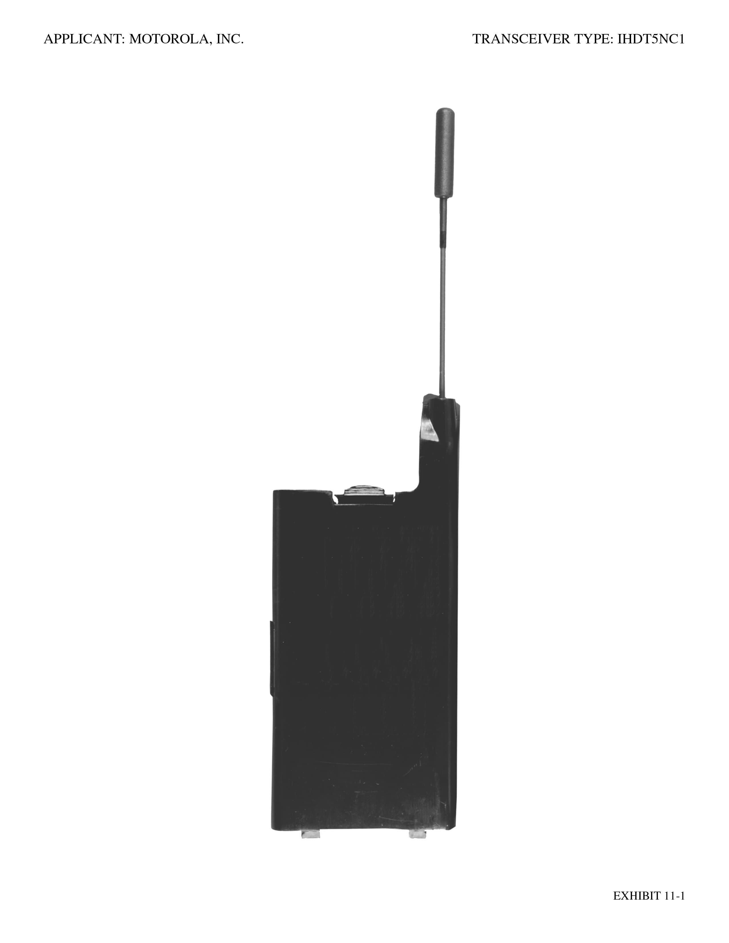
Click to zoom
Application Details
- Equipment Class
- TNE - Licensed Non-Broadcast Transmitter Held to Ear
- Date of Grant
- Nov 02, 1998
- Application Purpose
- Original Equipment
- Date of Application
- Sep 10, 1998
- Equipment Note
- Cellular Transceiver Module
- Frequency Range
- 824.00000000 - 849.00000000
- Company
- Motorola Mobility LLC
- Country
- United States
Documents & Files
Document Text
Text extracted from the exhibit documents filed with the FCC. Open a document above to read the original.
Users Manual
Satellite Series TM 9500 Portable Phone User’s Guide INDY.book Page 1 Thursday, August 20, 1998 8:57 AM Personal Communications Sector 600 North U.S. Highway 45 Libertyville, Illinois 60048 , , VibraCall, andTurboDial are registered trademarks of Motorola, Inc. Iridium, the Iridium logo, and Iridium World Service are registered trademarks and/or service marks of Iridium IP LLC. ©1998 Motorola, Inc. Printed in U.S.A. INDY.book Page 2 Thursday, August 20, 1998 8:57 AM iii Contents Welcome! Guide Overview . . . . . . . . . . . . . . . . . . . . . . . . . . . . . . . . . . . . . . 10 Technology Overview . . . . . . . . . . . . . . . . . . . . . . . . . . . . . . . . . . 13 Features Overview . . . . . . . . . . . . . . . . . . . . . . . . . . . . . . . . . . . . 16 Phone Overview . . . . . . . . . . . . . . . . . . . . . . . . . . . . . . . . . . . . . . 17 The Indicators . . . . . . . . . . . . . . . . . . . . . . . . . . . . . . . . . . . . . . . . 19 Package Contents and Options . . . . . . . . . . . . . . . . . . . . . . . . . . 22 Getting Started Battery Information . . . . . . . . . . . . . . . . . . . . . . . . . . . . . . . . . . . . 26 Removing the Battery Covers . . . . . . . . . . . . . . . . . . . . . . . . . . . . 27 Installing the Battery . . . . . . . . . . . . . . . . . . . . . . . . . . . . . . . . . . . 28 Checking the Battery . . . . . . . . . . . . . . . . . . . . . . . . . . . . . . . . . . 30 Charging the Battery . . . . . . . . . . . . . . . . . . . . . . . . . . . . . . . . . . . 32 What Is a SIM Card? . . . . . . . . . . . . . . . . . . . . . . . . . . . . . . . . . . . 34 Installing the SIM Card . . . . . . . . . . . . . . . . . . . . . . . . . . . . . . . . . 35 What is a Cellular Cassette? . . . . . . . . . . . . . . . . . . . . . . . . . . . . . 36 Installing the Cellular Cassette . . . . . . . . . . . . . . . . . . . . . . . . . . . 37 Using Your Phone Feature Overview . . . . . . . . . . . . . . . . . . . . . . . . . . . . . . . . . . . . . 40 Powering Up the Phone . . . . . . . . . . . . . . . . . . . . . . . . . . . . . . . . 41 Placing Calls . . . . . . . . . . . . . . . . . . . . . . . . . . . . . . . . . . . . . . . . . 43 Receiving Calls . . . . . . . . . . . . . . . . . . . . . . . . . . . . . . . . . . . . . . . 47 Ending a Call . . . . . . . . . . . . . . . . . . . . . . . . . . . . . . . . . . . . . . . . 49 Using Call Waiting . . . . . . . . . . . . . . . . . . . . . . . . . . . . . . . . . . . . . 50 Placing a Call on Hold . . . . . . . . . . . . . . . . . . . . . . . . . . . . . . . . . 51 + Muting a Call . . . . . . . . . . . . . . . . . . . . . . . . . . . . . . . . . . . . . . 53 Sending a Phone Flash . . . . . . . . . . . . . . . . . . . . . . . . . . . . . . . . . 54 Basic Phone Setup . . . . . . . . . . . . . . . . . . . . . . . . . . . . . . . . . . . . 55 Using the Menus Using the Options Menus . . . . . . . . . . . . . . . . . . . . . . . . . . . . . . . 58 + Using the Quick Access Menu . . . . . . . . . . . . . . . . . . . . . . . . 61 Using The In-Call Menu . . . . . . . . . . . . . . . . . . . . . . . . . . . . . . . . 63 Managing the Phone Book What’s on the Menu? . . . . . . . . . . . . . . . . . . . . . . . . . . . . . . . . . . . 66 Feature Overview . . . . . . . . . . . . . . . . . . . . . . . . . . . . . . . . . . . . . 67 Organizing Your Phone Book . . . . . . . . . . . . . . . . . . . . . . . . . . . . 68 INDY.book Page iii Thursday, August 20, 1998 8:57 AM iv Storing Names and Numbers . . . . . . . . . . . . . . . . . . . . . . . . . . . .70 Entering Names . . . . . . . . . . . . . . . . . . . . . . . . . . . . . . . . . . . . . .72 Using Pauses in Numbers . . . . . . . . . . . . . . . . . . . . . . . . . . . . . .74 + Using Phone Number Prefixes . . . . . . . . . . . . . . . . . . . . . . . . .75 Recalling Entries . . . . . . . . . . . . . . . . . . . . . . . . . . . . . . . . . . . . . .76 Calling, Modifying, or Erasing an Entry . . . . . . . . . . . . . . . . . . . . .78 + Checking Phone Book Capacity . . . . . . . . . . . . . . . . . . . . . . .79 + Preventing Access to the Phone Book . . . . . . . . . . . . . . . . . . .80 + Restricting Phone Use . . . . . . . . . . . . . . . . . . . . . . . . . . . . . . .81 Viewing the Last Ten Numbers Dialed . . . . . . . . . . . . . . . . . . . . .85 Viewing and Modifying Phone Numbers . . . . . . . . . . . . . . . . . . . .86 + One-Touch Dialing . . . . . . . . . . . . . . . . . . . . . . . . . . . . . . . . . .88 Using Calling Features What’s on the Menu? . . . . . . . . . . . . . . . . . . . . . . . . . . . . . . . . . . .90 Feature Overview . . . . . . . . . . . . . . . . . . . . . . . . . . . . . . . . . . . . .91 + Showing the Battery Meter . . . . . . . . . . . . . . . . . . . . . . . . . . . .92 + Showing Signal Strength . . . . . . . . . . . . . . . . . . . . . . . . . . . . .93 + Deactivating Pending Call Drop Signal . . . . . . . . . . . . . . . . . .94 Using Call Forwarding . . . . . . . . . . . . . . . . . . . . . . . . . . . . . . . . .95 + Activating Call Waiting . . . . . . . . . . . . . . . . . . . . . . . . . . . . . .100 Restricting Calls . . . . . . . . . . . . . . . . . . . . . . . . . . . . . . . . . . . . .101 Using Message Services What’s on the Menu? . . . . . . . . . . . . . . . . . . . . . . . . . . . . . . . . . .106 Feature Overview . . . . . . . . . . . . . . . . . . . . . . . . . . . . . . . . . . . .107 + Checking Your Voicemail . . . . . . . . . . . . . . . . . . . . . . . . . . . .108 + Storing Your Voicemail Number . . . . . . . . . . . . . . . . . . . . . . .109 Managing Your Messages . . . . . . . . . . . . . . . . . . . . . . . . . . . . .110 Accessing Messages . . . . . . . . . . . . . . . . . . . . . . . . . . . . . . . . .112 Customizing Phone Features What’s on the Menu? . . . . . . . . . . . . . . . . . . . . . . . . . . . . . . . . . .116 Feature Overview . . . . . . . . . . . . . . . . . . . . . . . . . . . . . . . . . . . .117 Adjusting Your…
Text truncated - open the document above for the full version.
Cover Letter(s)
August 21, 1998 Engineer- in-Charge Equipment Authorization Branch Federal Communications Commission We hereby certify that this transmit and receive equipment (FCC ID: IHDT5NC1) for dual-mode mobile station cellular use is capable of compliance with the July 1996 TIA/EIA IS-95-A, Mobile Station – Base Station Compatibility Standard for Dual Mode Wide Band Spread Spectrum Cellular System, and with OET bulletin No. 53 “Cellular System Mobile Station – Land Station Compatibility Specification”. ______________________________ Owen B. Thompson, Jr. Senior Staff Engineer Diversified Technologies Services Motorola, Inc. ______________________________ Ronald Young Engineering Manager Diversified Technologies Services Motorola, Inc.
Cover Letter(s)
September 11, 1998 CONFIDENTIALITY REQUEST CONTAINED WITHIN Federal Communications Commission Authorization and Evaluation Division 7435 Oakland Mills Road Columbia, Maryland 21046 Re:Application for Equipment Authorization (Type Acceptance) of a Portable Cellular Transceiver Module, FCC ID: IHDT5NC1 Gentlemen: Motorola, Inc., Cellular Subscriber Sector, 600 N. U.S. Highway 45, Libertyville, Illinois 60048-5343 herein submits "Electronic" Application for Equipment Authorization (to be followed by mailing of Check Number 120-659347 in the amount of $580.00 along with Form 159) for Type Acceptance of a Portable Cellular Transceiver Module under FCC Rule Part 22(H), FCC ID: IHDT5NC1. Motorola is also the manufacturer of this equipment. As we understand that a rule transition date is near, it is understood that the Equipment Authorization may be issued as a 'Certification' rather than as a 'Type Acceptance.' In addition to confidentiality for the entire application prior to grant (per 47CFR0.457(d)(1) (ii) ), Motorola requests, pursuant to 47CFR0.459, post-grant confidentiality for portions of the material contained in this application such that the identified material will be withheld from public inspection following the grant of this authorization. This material, as indicated by request for confidentiality of the items during the electronic submission process and further identified by their listing in RED on the List of Exhibits attached hereto, includes: Motorola un-numbered Exhibit, Information Regarding ESN Protection (Description 'ESN Security Statement,' submitted as 'Operational Description,' EAS Exhibit #12); Motorola Exhibit 4, List/Application of Semiconductors and/or Other Active Devices (Description 'Exhibit 4 Parts List,' submitted as 'Parts List/Tune Up Info,' EAS Exhibit #10); Motorola Exhibit 5, Circuit Diagrams (consisting of and submitted as three parts, one as Description 'Exhibit 5 Block Diagrams and Text,' submitted as 'Block Diagrams,' EAS Exhibit #4, and the other two as Descriptions 'Exhibit 5 Schematic 1' and Exhibit 5 Schematic 2,' submitted as 'Schematics,' EAS Exhibit #5); and Motorola Exhibit 6, Circuit Descriptions (submitted as 'Operational Description,' EAS Exhibit #12). Specifically, these exhibits contain information relating to circuit function and complexity that could be of benefit to competitors. This material contains Motorola's trade secrets and confidential information that Motorola does not customarily release to the public and which is otherwise not generally available to the public. Federal Communications Commission Authorization and Evaluation Division 7435 Oakland Mills Road Columbia, Maryland 21046 September 11, 1998 Page 2 This equipment has the capability to operate in both the conventional Analog Cellular standard and two Industry Interim standards. One, commonly called CDMA, is outlined in TIA/EIA IS-95-A "Mobile Station - Base Station Compatibility Standard for Dual-Mode Wideband Spread Spectrum Cellular System", dated May 1995. The second, referred to as N-AMPS or Narrow AMPS, is outlined in TIA/EIA IS-91-A "Mobile Station - Base Station Compatibility Standard for 800 MHz Analog Cellular, Auxiliary and Residential Services", dated November 1995. Technical details for these alternate cellular technologies (permitted under §22.901(d) of the Commission's rules) related to Type Acceptance of this equipment, as noted in paragraphs 31 and 32 of the Report and Order in FCC GEN. Docket No. 87-390, are detailed in item numbers 5 & 6 of Exhibit 2, and throughout the other exhibits as listed in item number 5 of Exhibit 2. Please contact me by telephone at (847) 523-7373, by facsimile at (847) 523-2350 or by correspondence at the address herein if there are any further questions or additional information needed concerning this filing. Regards, (signed, John A. Kalenowsky) John A. Kalenowsky Patent Engineer/FCC Liaison Cellular Subscriber Sector 600 N. U.S. Highway 45 Libertyville, IL 60048-5343 Enclosures APPLICANT: MOTOROLA, INC. TRANSCEIVER TYPE: IHDT5NC1 LIST OF EXHIBITS EXHIBIT DESCRIPTIONFCC REFERENCE (un-numbered) RADIO FREQUENCY ENERGY EXPOSURE 2.1093 EVALUATION STATEMENT (un-numbered) INFORMATION REGARDING ESN PROTECTION 22.919 (un-numbered) STATEMENT REGARDING COMPLIANCE WITH 22.933, OET 53 CELLULAR SYSTEM COMPATIBILITY SPECIFICATION 1 CERTIFICATION OF DATA 2.911 2 GENERAL INFORMATION PRODUCTION PLANS 2.983-C APPLICATION REFERENCES 2.1061 DATA SUBMITTAL PROCEDURE 2.999, 2.947 REPORT OF MEASUREMENTS UNDER CELLULAR SERVICE OPTION DETERMINATION OF ADDITIONAL EMISSION DESIGNATORS 3 DESCRIPTION TECHNICAL CHARACTERISTICS 2.983-D-1,2,3,4,5 4 LIST/APPLICATION OF SEMICONDUCTORS 2.983-D-6 AND/OR OTHER ACTIVE DEVICES 5 CIRCUIT DIAGRAMS (INDEX) 2.983-D-7 6 CIRCUIT DESCRIPTION (INDEX) 2.983-D-10-11-12 6A MEANS FOR FREQUENCY STABILIZATION 6B MEANS FOR ATTENUATION OF SPURIOUS EMISSIONS 6C MEANS FOR LIMITING MODULATION 6D MEANS FOR ATTENUATION OF HIGHER AUDIO FREQUENCIES 6E MEANS FOR LIMITING POWER OUTPUT 6F DIGITAL MODULATION TECHNIQUES 7 INSTRUCTION MANUAL 2.983-D-8 8 TRANSMITTER ADJUSTMENTS (INDEX) 2.983-D-9 9 MEASURED DATA (INDEX) 2.983-E 9A R.F. OUTPUT - MEASURED DATA 2.985 9B-1,2 AUDIO RESPONSE - GRAPH 2.987 9C POST LIMITER LOW-PASS RESPONSE - GRAPH 2.987 9D-1,2 SIGNALING CHANNEL AUDIO ROLL-OFF 2.987 FILTER RESPONSE 9E-1,2,3,4 MODULATION LIMITING - GRAPHS 2.987 9F-1,2,3,4,5,6,7 OCCUPIED BANDWIDTH - PLOTS 2.989 9G CONDUCTED SPURIOUS EMISSIONS - GRAPH 2.991 9H RADIATED SPURIOUS EMISSIONS - GRAPH 2.993 9J-1,2,3 FREQUENCY STABILITY vs. TEMPERATURE - GRAPH 2.995 9K-1,2,3 FREQUENCY STABILITY vs. VOLTAGE - GRAPH 2.995 10 IDENTIFICATION (NAMEPLATE) INFORMATION 2.983-F 11-1,2,5,6 EXTERNAL PHOTOGRAPHS 2.983-G APPLICANT: MOTOROLA, INC.TRANSCEIVER TYPE: IHDT5NC1 11-3,4INTERNAL PHOTOGRAPHS2.983-G 12MEASUREMENT TECHNIQUES2.947
ID Label/Location Info
APPLICANT: MOTOROLA, INC.TRANSCEIVER TYPE: IHDT5NC1 EXHIBIT 10 FCC IDENTIFICATION (NAMEPLATE) INFORMATION The Equipment ID label above is representative (in size and in showing the FCC Identifier as it will appear) of the actual label that will appear on the equipment when in production. Its location is shown in Exhibit 11-2. FCC ID: IHDT5NC1 SCALE 2:1
Operational Description
APPLICANT: MOTOROLA, INC. TRANSCEIVER TYPE: IHDT5NC1 EXHIBIT 2 GENERAL INFORMATION 1. Production Plans - Pursuant 2.983(c) Quantity production is planned. 2. Application References - Pursuant 2.1061 Reference is made to the following Motorola "Application References" on file with the Commission. None. 3. Data Submittal Procedure - Pursuant 2.999, 2.947 Data is supplied in accordance with Part 2, Subpart J of the Commission’s rules. Standards used on measurements supplied are TIA/EIA IS-88, TIA/EIA IS-90, TIA/EIA IS-95-A, TIA/EIA IS-98 and OST 53. 4. Similar to "Currently Type Accepted Transmitter Type(s):" FCC ID: IHDT5XA1 This transceiver is based on the same design as FCC ID: IHDT5YD1, (type acceptance granted September 29, 1998). The primary difference is that this device has been repackaged mechanically to be inserted into an IRIDIUM communications system handset (see Exhibits 7 and 11) and can function as a self contained RF transceiver module to provide alternative terrestrial cellular service to the handset. All power and user interface functions (transmit and receive audio, keypad operations and display) are provided by the IRIDIUM handset 5. Report of measurements pertaining to types of emission, frequency range, maximum output power and modulation techniques for CDMA and Narrow Analog Modes of Operation (reference paragraphs 31 and 32 of the Report and Order in FCC GEN. Docket No. 87-390). The "Motorola NAMPS Air Interface Specification", referenced in Motorola’s earlier applications for equipment capable of Narrow Analog Mode Operation, has been replaced. Through the efforts of the Telecommunications Industry Association’s TR- 45.1 Subcommittee on Analog Cellular, TIA/EIA Interim Standard IS-88 - "Mobile Station - Land Station Compatibility Standard for Dual-Mode Narrow band Analog Cellular Technology" (TIA/EIA IS-88) and TIA/EIA Interim Standard IS-90 - "Recommended Minimum Standard for 800 MHz Dual-Mode Narrow band Analog Cellular Subscriber Units" (TIA/EIA IS-90), both dated January 1993, were developed and, as they apply to cellular subscriber equipment, are incorporated herein by reference. APPLICANT: MOTOROLA, INC. TRANSCEIVER TYPE: IHDT5NC1 EXHIBIT 2 A. Types of emission This equipment continues to be capable of the existing, approved emissions for previously existing equipment designed and approved for operation in the Domestic Public Cellular Radio Telecommunications Service in the Wide Analog Mode. In the Narrow Analog Mode, a new emission designator 17K4F9W is added, determined as explained in section 6 of this exhibit. Reference is also made to TIA/EIA IS-88 and TIA/EIA IS-90. Actual measurements of Occupied Bandwidth for the Narrow Analog Mode are shown in Exhibits 9F-5 and 9F-6. In the Digital CDMA Mode, a new emission designator 1M25F9W is added, determined as explained in section 6 of this exhibit. Reference is also made to TIA/EIA IS-95-A. Actual measurements of Occupied Bandwidth for the Digital CDMA Mode are shown in Exhibit 9F-7. Spurious Emissions (Conducted and Radiated) reported in Exhibits 9G and 9H are the worst (highest level) of Wide, Narrow and Digital Modes. B. Frequency range The frequency range of the equipment is the Domestic Public Cellular Radio Telecommunications Service bands, 824 - 849 MHz and 869 - 894 MHz, regardless of whether in Wide, Narrow or Digital Mode. In Wide Analog Mode, the channel spacing is 30 kHz on signaling channels and voice channels. In Narrow Analog Mode, however, the channel spacing is 10 kHz on voice channels. In Digital CDMA Mode, the channel increment is 30 kHz for all data and voice channels although centers of adjacent CDMA channels are typically spaced a minimum of 1.23 MHz apart as well as minimum of 0.69 MHz away from the band edges. Again, reference is made to TIA/EIA IS-88, TIA/EIA IS-90, TIA/EIA IS-95, and EIA/TIA IS-98. Frequency Stability versus Temperature and Voltage measurements is shown in Exhibits 9J-1,2,&3 and 9K-1,2&3. This equipment uses Automatic Frequency Control (AFC) to lock to within 0.75 part per million (steady state) of the frequency received from the Land Station system for Analog Mode, and to within ± 300 Hz of the received frequency from the Land Station system for Digital Mode. Also refer to Exhibit 6A. C. Maximum output power Analog Mode Radio Frequency Output Power is independent of whether the equipment operates in the Wide or Narrow Mode. Power output capability of the Mobile Station equipment is still reported to the Land Station system (via the Mobile Station Power Class in the Station Class Mark) and the Mobile Station will respond to APPLICANT: MOTOROLA, INC. TRANSCEIVER TYPE: IHDT5NC1 EXHIBIT 2 commands from the Land Station system to change power levels as defined in the specifications. Digital Mode The maximum radio frequency power allowed per the standard ranges from 0.2 Watts to 1.0 Watt. The mobile maximum output power during a power control group is within the specified limits and is controlled by commands from a Land Station system. R. F. Output Power measurement results are shown in Exhibit 9A. D. Modulation techniques Analog Mode Modulation in the Narrow Mode is conventional Frequency Modulation with peak frequency deviation lower than that of Wide Mode. The highest modulating frequency is also reduced in Narrow Mode by replacing the nominal 6 kHz Supervisory Audio Tone (SAT) and 10 kHz Signaling Tone (ST)/Data signals of Wide Analog Mode with a 200 bit/second Digital SAT (DSAT) or Digital ST (DST) signal or 100 Manchester bit/second Data signal to accomplish the supervision, signaling and command/control functions between the Mobile and Land stations. The highest modulating frequency is then the maximum voice path frequency, 3000 Hz. The peak deviation of the voice signal for Narrow Mode is 5 kHz. The peak deviation of the DSAT, DST or Data signal for Narrow Mode is 0.7 kHz. The end result is that less bandwidth is needed to accomplish communications in Narrow Mode …
Text truncated - open the document above for the full version.
Operational Description
APPLICANT: MOTOROLA, INC. TRANSCEIVER TYPE: IHDT5NC1 EXHIBIT 3 DESCRIPTION 1. Transmitter Technical Characteristics--Pursuant 2.983(d) A. R.F. Power Output: In analog mode, the power output is continuous and has a variable range from .005 to 0.5 Watts (controlled by the Cell-site). In digital mode, power output ranges from 0.00001 mW to 0.250 Watts (controlled by the Cell site via Closed Loop Power Control). The power output varies depending on the mobile’s data rate. Transmit duty cycle is 100% in 14400 bps, 50% in 7200 bps, 25% in 3600 bps, and 12.5% in 1800 bps. B. Frequency Range 824.04 to 848.97 MHz for Wide Analog Mode and Digital CDMA Mode Frequency Range 824.01 to 848.99 MHz for Narrow Analog Mode C. Frequency Stability +/-0.000075% (0.75PPM) steady state of the receive carrier frequency (Analog Modes). NAMPS operational stability: ± .00010% (1.0 PPM) AMPS operational stability: ± .00025% (2.5 PPM) +/-0.000036% (0.36PPM) steady state of the receive carrier frequency (Digital Modes). CDMA operational stability: ± .00005% (0.5 PPM) D. Emissions 40K0F8W, 40K0F1D, 17K4F9W, 1M25F9W E. D.C. Voltage into the Final two stage R.F. Amplifier: 3.58 Volts DC D.C. Current into the Final two stage R.F. Amplifier: 790 mA (Analog) D.C. Current into the Final two stage R.F. Amplifier: 460 mA (Digital) (Average Current in Digital CDMA Mode in 100% transmit duty cycle) 2. Transmitter Application A. Power Supply Available The transmitter is normally operated by means of the unregulated and unconditioned 3.6 volt (nominal) battery source of the IRIDIUM handset. The low voltage cutoff is set to 2.9V. Performance is also guaranteed up to 5.4V. (Refer to Exhibit 9K) B. Antenna Available The transmitter is designed to be used with an integral extendable antenna. In the down position, the antenna is a quarter wave helical. In the up position, the antenna is a quarter wave whip in series with a quarter wave helical. C. Maximum Transmit Channel Capability AMPS Mode - 832 channels NAMPS Mode - 2412 channels CDMA Mode - Per 6.1.1.1 of TIA/EIA IS-95-A
Parts List/Tune Up Info
APPLICANT: MOTOROLA, INC.TRANSCEIVER TYPE: IHDT5NC1 TRANSCEIVER ADJUSTMENTS/TUNE-UP PROCEDURE EXHIBIT 8 There are no user accessible adjustments or tuning in this portable cellular transceiver module. All necessary adjustments and tuning are performed during manufacture of the product. Any adjustments or tuning after service or repair are done as part of that process as special equipment is required to perform such adjustments.
RF Exposure Info
P P a a g g e e 1 1 October 22, 1998 SAR Test Report for Motorola portable cellular phone module (FCC ID IHDT5NC1). Prepared by: Paul Moller, Principal Staff Engineer Motorola Personal Communications Sector Product Safety Laboratory Libertyville, Illinois Contents 1) Introduction 2) Applicable Regulations 3) Description of Test Sample 4) Description of Motorola SAR Test Facility 5) Test Sample Conditions 6) Method of Measurement 7) SAR Test Results 8) Summary Appendix A: Included data Appendix B: SAR Measurement Operational Guide P P a a g g e e 2 2 1. Introduction The Motorola Personal Communications Sector Product Safety Laboratory has performed measurements of the maximum potential exposure to the user of portable cellular phone module, FCC ID IHDT5NC1. The Specific Absorption Rate (SAR) of this product was measured. This report details the test setup and equipment as well as the results of those tests. 2. Applicable Regulations Federal Communications Commission rule §2.1093(d)(2), the ANSI/IEEE C95.1 1992 and the NCRP Report Number 86 specify the maximum exposure limit of 1.6 W/kg as averaged over any 1 gram of tissue for portable devices being used within 20cm of the user in the uncontrolled environment. 3. Description of Test Sample A prototype unit serial number P6V2 was measured. This unit is identical in physical construction, maximum radiated power levels and antenna structure to units that will be in production. The portable cellular phone is a transceiver module that has been designed to be mechanically inserted into an IRIDIUM communications system handset, and can function as a self contained RF transceiver module to provide alternative terrestrial cellular service to the IRIDIUM handset. A picture of the module is shown as figure 1. It transmits in the frequency range of 824 to 849 MHz using AMPS/NAMPS (analog) and CDMA (digital) modes. The maximum average transmit power for this test unit is 0.5 Watt in analog modes, and 0.25 Watt in digital mode. Figure 1. The module is equipped with a telescoping antenna that serves as both a receive and transmit antenna. The antenna has a retracted and an extended operating position and is shown installed in the IRIDIUM handset as figures 2 and 3 respectively. Since the module inserts into the back side of the IRIDIUM communications system handset, a view of the back of the P P a a g g e e 3 3 complete package is shown in figure 4. Note that in figure 4 the IRIDIUM antenna is in its stowed, or unused, position. Figure 5 is the same as figure 4 only with the IRIDIUM antenna removed and a dust cover inserted in the IRIDIUM phone’s antenna socket. Figure 2. Figure 3. P P a a g g e e 4 4 Figure 4. Figure 5. P P a a g g e e 5 5 Figures 6 and 7 show the test unit as it is placed onto the phantom head with the modules antenna in the retracted and extended positions respectively. For the purposes of the actual SAR tests the phantom head is tilted on its side by 90 degrees so that a vertically oriented measurement probe can easily scan an area where the phone is in close contact with the phantom and the SAR will be the highest. Figure 6. P P a a g g e e 6 6 Figure 7. 4. SAR Test Facility The Motorola test facility utilized for the SAR testing of this product is the Personal Communications Sector Product Safety Laboratory, in Libertyville Illinois. The laboratory utilizes an SAR measurement system developed by Motorola and manufactured by IDX Robotics™ of Corvallis, Oregon. This system utilizes a computer controlled six axis robot to move a measurement probe to measure the SAR. The probe is calibrated at the Florida Corporate Electromagnetics Laboratory in Plantation Florida, using a procedure developed by Dr. Q. Balzano. The measurement methodology is described in IEEE Transactions on Vehicular Technology, vol. 44, no. 3, August 1995, titled Electromagnetic Energy Exposure of Simulated users of Portable Cellular Telephones. P P a a g g e e 7 7 Furthermore, a copy of the document “SAR Measurement Operational Guide”, dated December 1997, is attached as appendix B for reference purposes. This Motorola document describes the measurement setup and rationale in detail. 5. Test Sample Conditions For the purposes of these tests the subject phone was positioned on the measurement phantom per the instructions in the Motorola users manual for the subject phone. SAR was measured with the module’s antenna in both the retracted and extended positions. Since the antenna is not located on the center of the phone, the SAR was measured with the phone on both the left and right side talk positions (See figures 6 and 7). Due to the construction of the phone, the base of the module’s antenna is as little as 51 mm away from the cheek of the phantom. The test sample is capable of operation in a test mode that allows control of the transmitter without the need to place actual phone calls. This guarantees that the module does not change its transmitter power, and that the resultant SAR values will not be affected by external connections. For the purposes of this test the module is commanded to test mode and manually set to the proper channel, transmitter power level and transmit mode of operation. The phone is then placed in the SAR measurement system with a fully charged battery. At the end of each test the module is measured for RF power out so as to ensure that the test was evaluating the maximum SAR level. For the purposes of these tests, the module’s transmitter was operated at the highest transmitter output (full rate on the vocoder for digital mode), with the antenna in both the extended and retracted positions, and with the phone on both left and right side talk positions. 6. Method of Measurement For each antenna position the system is instructed to scan as much of the face of the phone as is in close proximity to the phantom. Using the information gained about the general region of highest SAR, the system then automatically scans a smaller area center…
Text truncated - open the document above for the full version.
Test Report
APPLICANT: MOTOROLA, INC. TRANSCEIVER TYPE: IHDT5NC1 EXHIBIT 9 SUBMITTED MEASURED DATA INDEX EXHIBITMEASUREMENT 9ARF Power Output-Measured Data 9B-1Audio Response Wide Mode - Graph 9B-2Audio Response Narrow Mode - Graph 9CPost Limiter Low Pass Filter Response - Graph 9D-1Signaling Channel Audio Roll-Off Filter Response-Graph 9D-2DSAT Audio Roll-Off Filter Response - Graph 9E-1Modulation Limiting (Compander In Wide Mode) - Graph 9E-2Modulation Limiting (Compander Out Wide Mode) - Graph 9E-3Modulation Limiting (Compander In Narrow Mode) - Graph 9E-4Modulation Limiting (Compander Out Narrow Mode) - Graph 9F-1Occupied Bandwidth, Audio (Wide Mode) - Plot 9F-2Occupied Bandwidth, Audio and SAT - Plot 9F-3Occupied Bandwidth, Signaling Tone and SAT - Plot 9F-4Occupied Bandwidth, Wide band Data - Plot 9F-5Occupied Bandwidth, Audio (Narrow Mode) - Plot 9F-6Occupied Bandwidth, Audio and DSAT- Plot 9F-7Occupied Bandwidth, Audio and Data (Digital Mode) - Plot 9GConducted Spurious and Harmonic Emissions - Graph 9HRadiated Spurious and Harmonic Emissions - Graph 9J-1Frequency Change vs. Temperature (Wide Mode) - Graph 9J-2Frequency Change vs. Temperature (Narrow Mode) - Graph 9J-3Frequency Change vs. Temperature (Digital Mode) - Graph 9K-1Frequency Change vs. Supply Voltage (Wide Mode) - Graph 9K-2Frequency Change vs. Supply Voltage (Narrow Mode) - Graph 9K-3Frequency Change vs. Supply Voltage (Digital Mode) - Graph APPLICANT: MOTOROLA, INC. TRANSCEIVER TYPE: IHDT5NC1 EXHIBIT 9B-1 RF POWER OUTPUT DATA The input supply to the transmitter was set at 3.6 Volts. The RF power output was measured with the indicated voltage and current applied into the final RF amplifying device(s). ANALOG MODE Measured RF output: 0.562 W Measured DC voltage: 3.58 V Measured DC current: 790 mA Measured RF input: 7.2 mW DIGITAL MODE In Digital Mode the values measured for RF Output, DC Current and RF Input Power are all average values which reflect a 100% transmit duty cycle in CDMA operation. Measured RF output: 0.240 W Measured DC voltage: 3.68 V Measured DC current: 460 mA Measured RF input: 0.69 mW Effective Radiated Power Since the unit is intended for use with a provided antenna (and “non-standard” RF connector), the maximum ERP is determined by measuring the maximum antenna gain in any direction relative to an ideal dipole antenna and adding this gain to the rated conducted output power applied to the antenna. The maximum ERP was found to occur in Analog mode with the antenna in the extended position. Maximum Effective Radiated Power: 27.85 dBm …
Text truncated - open the document above for the full version.
Contact Information
Applicant
Jeff Narducci(Director Product Compliance)
Technical Specifications
| # | Rule Parts | Frequency Range | Power Output | Emission | Tolerance |
|---|---|---|---|---|---|
| 4 | 22.901(d) | 824 MHz - 849 MHz | 310.00 mW | 1M25F9W | 0.00005 % |
Other Applications from Motorola Mobility LLC
IHDT56AW9
May 12, 2026Smart Watch
Equipment Class
NII - Unlicensed National Information Infrastructure TXIHDT56AW5
Apr 08, 2026Mobile Cellular Phone
Equipment Class
DTS - Digital Transmission SystemIHDT56AW6
Mar 18, 2026Smart Watch
Equipment Class
JBP - Part 15 Class B Computing Device PeripheralIHDT56AX4
Mar 17, 2026Mobile Cellular Phone
Equipment Class
PCE - PCS Licensed Transmitter held to earIHDT56AW3
Mar 03, 2026Mobile Cellular Phone
Equipment Class
6XD - 15E 6 GHz Low Power Indoor Client