IHDT5YV1Portable Cellular Transceiver
Motorola Mobility LLC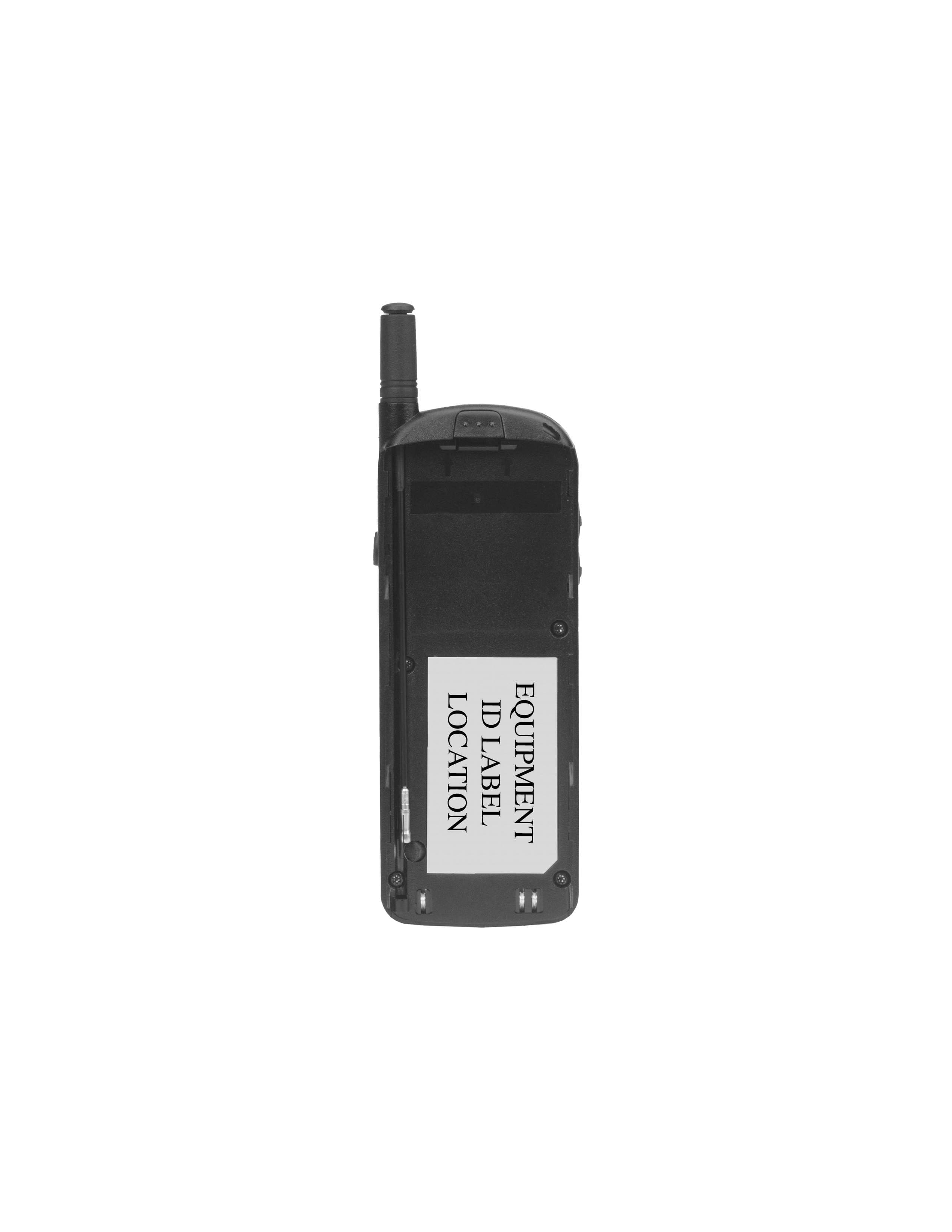
Click to zoom
Application Details
- Equipment Class
- TNE - Licensed Non-Broadcast Transmitter Held to Ear
- Date of Grant
- Mar 03, 1999
- Application Purpose
- Original Equipment
- Date of Application
- Nov 05, 1998
- Equipment Note
- Portable Cellular Transceiver
- Frequency Range
- 824.00000000 - 849.00000000
- Company
- Motorola Mobility LLC
- Country
- United States
Documents & Files
Document Text
Text extracted from the exhibit documents filed with the FCC. Open a document above to read the original.
Users Manual
APPLICANT: MOTOROLA, INC. TRANSCEIVER TYPE: IHDT5YV1 EXHIBIT 7 A preliminary user manual follows. 1 Welcome Thank you for choosing Motorola—a global leader in communications technology.All Motorola phones are designed and manufactured in the United States to meet Motorola’s exacting specifications and world-class quality standards. During development, our laboratory testing team took the durable SC-3160 phone through its paces. They cooked it, steamed it, shook it, shocked it, dusted it, and dropped it—and the phone still worked! We are confident that the one you purchased will meet your own exacting standards.Thank you for choosing Motorola, and by all means, enjoy your SC-3160 dual mode digital cellular phone! 2 Guide Overview Okay , you’ve got a brand new phone with a bunch of nifty features.Now what?Afraid you’ll press the wrong key? Or forget a feature or two?Don’ t sweat it! W e’ve designed this guide to take you step-by-step through each feature of your new SC-3160 phone. W e’ll show you what key to press and what happens when you press it. Follow along, chapter -by-chapter , and you’ll fi nd it’ s as easy as 1-2-3. Here’ s an idea of what you’ll learn in each chapter: Getting Started First things fi rst. T urn to page 10 , and we’ll explain what came with your phone. Then, we’ll show you how to install and charge your battery so that you can get started with “The Basics” in the next section. The Basics What do all those buttons and lights mean? How do I make my fi rst phone call? In this section, we’ll answer those questions and get you going with your SC-3160 phone. Start learning “The Basics” on page 18 . 3 Guide Overview Using Memory Read “Using Memory ,” beginning on page 32 , and you’ll learn how to make the most of your new phone’ s built-in Phone Book. Y ou’ll save time with dialing shortcuts and memory tricks that make it easy to place quick calls. Using Messaging Did you know that your SC-3160 phone supports optional messag- ing services, like Caller ID * , which allows you to see who’ s calling before you answer? Y our new phone can even receive alphanu- meric messages just like a pager and tell you when you have V oice Mail*. Simply turn to page 42 to begin “Using Messaging.” The W orks When you’re ready to get into the more advanced features your new phone has to offer , just turn to page 50 for “The W orks.” Learn about everything from navigating the menu system to elec- tronically locking your phone.So relax! Let us show you what your SC-3160 phone can do! * Contact your Service Provider for availability . 4 Contents Introduction Safety Information . . . . . . . . . . . . . . . . . . . . . . . . . . . . 6 Getting Started Package Content Options . . . . . . . . . . . . . . . . . . . . . . 10 Introduction to Batteries . . . . . . . . . . . . . . . . . . . . . . . 11 Installing Batteries . . . . . . . . . . . . . . . . . . . . . . . . . . . 12 Charging Batteries . . . . . . . . . . . . . . . . . . . . . . . . . . . 13 Phone Overview . . . . . . . . . . . . . . . . . . . . . . . . . . . . . . 17 The Basics T urning Y our Phone On . . . . . . . . . . . . . . . . . . . . . . . 18 Reading the Indicators . . . . . . . . . . . . . . . . . . . . . . . . 20 Placing and Ending Calls . . . . . . . . . . . . . . . . . . . . . . 24 Receiving Calls . . . . . . . . . . . . . . . . . . . . . . . . . . . . . . 25 Redialing Numbers . . . . . . . . . . . . . . . . . . . . . . . . . . . 27 Basic T one Controls . . . . . . . . . . . . . . . . . . . . . . . . . . 28 Y our Phone & Its Shortcuts . . . . . . . . . . . . . . . . . . . . 30 Using Memory Introduction . . . . . . . . . . . . . . . . . . . . . . . . . . . . . . . . 32 Making the Most of Memory . . . . . . . . . . . . . . . . . . . 33 Storing . . . . . . . . . . . . . . . . . . . . . . . . . . . . . . . . . . . . . 34 Recalling . . . . . . . . . . . . . . . . . . . . . . . . . . . . . . . . . . . 36 Pause Dialing . . . . . . . . . . . . . . . . . . . . . . . . . . . . . . . 40 5 Contents Using Messaging Introduction . . . . . . . . . . . . . . . . . . . . . . . . . . . . . . . . . 42 Receiving Messages . . . . . . . . . . . . . . . . . . . . . . . . . . . 43 V iewing Y our Caller IDs . . . . . . . . . . . . . . . . . . . . . . . . 44 Checking Y our V oice Mail . . . . . . . . . . . . . . . . . . . . . . 46 Reading Y our Messages . . . . . . . . . . . . . . . . . . . . . . . . 48 The W orks Introducing the Menu Features . . . . . . . . . . . . . . . . . . 50 The Internal Phone Book . . . . . . . . . . . . . . . . . . . . . . 52 Learn how to store and recall numbers Using Call T imers . . . . . . . . . . . . . . . . . . . . . . . . . . . . 60 Learn how to monitor the length of your calls Setting T one Controls . . . . . . . . . . . . . . . . . . . . . . . . . . 66 Learn how to adjust your phone’ s tone controls Lock/Security Features . . . . . . . . . . . . . . . . . . . . . . . . . 72 Learn how to control access to your phone Phone Options . . . . . . . . . . . . . . . . . . . . . . . . . . . . . . . 80 Learn how to personalize your phone’ s operation Reference Information Accessory Options . . . . . . . . . . . . . . . . . . . . . . . . . . . . . 92 T roubleshooting . . . . . . . . . . . . . . . . . . . . . . . . . . . . . . 95 Glossary . . . . . . . . . . . . . . . . . . . . . . . . . . . . . . . . . . . . 97 Index . . . . . . . . . . . . . . . . . . . . . . . . . . . . . . . . . . . . . 104 6 Safety Information Exposure to Radio Frequency Signals Y our wireless handheld portable telephone is a low power radio transmitter and receiver . When it is ON, it receives and also sends out radio frequency (RF) signals. In August 1996, the Federal Communications Commissions (FCC) adopted RF exposure guidelines with safety levels for hand-held wireless phones. Those guidelines are consistent with the safety standards previously set by both U.S. and international standards bodies: • ANSI C95.1 (1992) * • NCRP Report 86 (1986)* • ICNIRP (1996…
Text truncated - open the document above for the full version.
Attestation Statements
APPLICANT: MOTOROLA, INC. TRANSCEIVER TYPE: IHDT5YV1 EXHIBIT 1 STATEMENT OF CERTIFICATION The technical data supplied with this application, having been taken under my supervision is hereby duly certified. The following is a statement of my qualifications: BSEE 1967 Purdue University, West Lafayette, Indiana MSEE 1972 Purdue University, West Lafayette, Indiana 18 years experience in cellular radiotelephone design SIGNATURE: (signed) NAME:Anthony E. Akers DATE:11/20/98 POSITION:Director of Engineering Motorola, Inc. I hereby certify that the above application was prepared under my direction and that to the best of my knowledge and belief, the facts set forth in the application and accompanying technical data are true and correct SIGNATURE: (signed) NAME:Anthony E. Akers DATE:11/20/98 POSITION:Director of Engineering Motorola, Inc.
Cover Letter(s)
November 30, 1998 CONFIDENTIALITY REQUEST CONTAINED WITHIN Federal Communications Commission Authorization and Evaluation Division 7435 Oakland Mills Road Columbia, Maryland 21046 Re:Application for Equipment Authorization (Certification) of a Portable Cellular Transceiver, FCC ID: IHDT5YV1 Gentlemen: Motorola, Inc., Cellular Subscriber Sector, 600 N. U.S. Highway 45, Libertyville, Illinois 60048-5343 herein submits "Electronic" Application for Equipment Authorization (to be followed by submission of Check Number 120-668200 in the amount of $610.00 along with Form 159) for Certification of a Portable Cellular Transceiver under FCC Rule Part 22(H), FCC ID: IHDT5YV1. In addition to confidentiality for the entire application prior to grant (per 47CFR0.457(d)(1) (ii) ), Motorola requests, pursuant to 47CFR0.459, post-grant confidentiality for portions of the material contained in this application such that the identified material will be withheld from public inspection following the grant of this authorization. This material, as indicated by request for confidentiality of the items during the electronic submission process and further identified by their listing in RED on the List of Exhibits attached hereto, includes: Un-numbered Exhibit, Information regarding Electronic Serial Number (ESN) Protection (Description 'Motorola Information Regarding ESN Protection' submitted as 'Operational Description,' EAS Exhibit #12); Motorola Exhibit 5, Circuit Diagrams (consisting of and submitted as two parts, one as Description 'Motorola Exhibit 5 Index and 5A Block Diagram,' submitted as 'Block Diagrams,' EAS Exhibit #4, and the other as Description 'Motorola Exhibit 5B 5C 5D 5E 5F 5G 5H Schematics,' submitted as 'Schematics,' EAS Exhibit #5); and Motorola Exhibit 6, Circuit Descriptions (Description 'Motorola Exhibit 6 Circuit Descriptions,' submitted as 'Operational Description,' EAS Exhibit #12). Specifically, these exhibits contain information relating to circuit function and complexity which could be of benefit to competitors. This material contains confidential business information and trade secrets of Motorola which are not customarily released to the public and which are otherwise not generally available to the public. Federal Communications Commission Authorization and Evaluation Division 7435 Oakland Mills Road Columbia, Maryland 21046 November 30, 1998 Page 2 This equipment has the capability to operate in both the conventional Analog Cellular standard and a new Industry Interim Standard, commonly called CDMA, as outlined in TIA/EIA IS-95-A "Mobile Station - Base Station Compatibility Standard for Dual-Mode Wideband Spread Spectrum Cellular System", dated May 1995. Technical details for this alternate cellular technology (permitted under §22.901(d) of the Commission's rules) related to Type Acceptance of this equipment, as noted in paragraphs 31 and 32 of the Report and Order in FCC GEN. Docket No. 87-390, are detailed in item numbers 5 & 6 of Exhibit 2, and throughout the other exhibits as listed in item number 5 of Exhibit 2. Information concerning compliance with rule provisions regarding Electronic Serial Numbers (per §22.919) is provided as an Operational Description. Please contact me by telephone at (847) 523-7373, by facsimile at (847) 523-2350 or by correspondence at the address herein if there are any further questions or additional information needed concerning this filing. Regards, (signed, John A. Kalenowsky) John A. Kalenowsky Patent Engineer/FCC Liaison Cellular Subscriber Sector 600 N. U.S. Highway 45 Libertyville, IL 60048-5343 Enclosures APPLICANT: MOTOROLA, INC.TRANSCEIVER TYPE: IHDT5YV1 LIST OF EXHIBITS EXHIBITDESCRIPTIONFCC REFERENCE (un-numbered)STATEMENT REGARDING COMPLIANCE WITH 22.933, OET 53 CELLULAR SYSTEM COMPATIBILITY SPECIFICATION (un-numbered)RADIO FREQUENCY ENERGY EXPOSURE 2.1093 EVALUATION STATEMENT (un-numbered)*INFORMATION REGARDING ESN PROTECTION22.919 1CERTIFICATION OF DATA2.911 2GENERAL INFORMATION APPLICATION REFERENCES2.1061 DATA SUBMITTAL PROCEDURE2.1041, 2.947 REPORT OF MEASUREMENTS FOR ALTERNATIVE CELLULAR TECHNOLOGY DETERMINATION OF ADDITIONAL EMISSION DESIGNATORS 3DESCRIPTION TECHNICAL CHARACTERISTICS2.1033-C-4,5,6,7 5*CIRCUIT DIAGRAMS (INDEX)2.1033-C-10 6*CIRCUIT DESCRIPTION (INDEX)2.1033-C-10,13 6A*MEANS FOR FREQUENCY STABILIZATION 6B*MEANS FOR ATTENUATION OF SPURIOUS EMISSIONS 6C*MEANS FOR LIMITING MODULATION 6D*MEANS FOR ATTENUATION OF HIGHER AUDIO FREQUENCIES 6E*MEANS FOR LIMITING POWER OUTPUT 6F*DIGITAL MODULATION TECHNIQUES 7INSTRUCTION MANUAL 2.1033-C-3 8TRANSMITTER ADJUSTMENTS2.1033-C-9 9MEASURED DATA (INDEX)2.1033-C-14 9AR.F. OUTPUT - MEASURED DATA2.1046, 2.1033-C-8 9BAUDIO RESPONSE - GRAPH2.1047 9CPOST LIMITER LOW-PASS RESPONSE - GRAPH2.1047 9DSIGNALING CHANNEL AUDIO ROLL-OFF FILTER RESPONSE2.1047 9E-1,2MODULATION LIMITING - GRAPHS2.1047 9F-1,2,3,4,5OCCUPIED BANDWIDTH - PLOTS2.1049 9GCONDUCTED SPURIOUS EMISSIONS - GRAPH2.1051, 2.1057 9HRADIATED SPURIOUS EMISSIONS - GRAPH2.1053, 2.1057 9J-1,2FREQUENCY STABILITY vs. TEMPERATURE - GRAPH2.1055 9K-1,2FREQUENCY STABILITY vs. VOLTAGE - GRAPH2.1055 10IDENTIFICATION (NAMEPLATE) INFORMATION2.1033-C-11 11-1,2EXTERNAL PHOTOGRAPHS2.1033-C-12 11-3,4INTERNAL PHOTOGRAPHS2.1033-C-12 12MEASUREMENT TECHNIQUES2.1041, 2.947 * In RED indicates submitted with Request for Post-Grant Confidentiality.
External Photos
APPLICANT: MOTOROLA, INC.TRANSCEIVER TYPE: IHDT5YV1 EXHIBIT 11-1 TRANSCEIVER TYPE: IHDT5YV1APPLICANT: MOTOROLA, INC. EXHIBIT 11-2
ID Label/Location Info
APPLICANT: MOTOROLA, INC.TRANSCEIVER TYPE: IHDT5YV1 EXHIBIT 10 FCC IDENTIFICATION (NAMEPLATE) INFORMATION FCC ID: IHDT5YV1 The FCC label shown is representative of the label that will appear on the radio when in production. It will be placed on the radio telephone as shown in Exhibit 11-2. Other information may also be included on this label.
Operational Description
APPLICANT: MOTOROLA, INC. TRANSCEIVER TYPE: IHDT5YV1 EXHIBIT 2 GENERAL INFORMATION 1.Production Plans - Pursuant 2.1033(c) Quantity production is planned. 2.Application References - Pursuant 2.1061 None 3.Data Submittal Procedure - Pursuant 2.999, 2.947 Data is supplied in accordance with Part 2, Subpart J of the Commission's rules. Standards used on measurements supplied are TIA/EIA IS-95-A, TIA/EIA IS-98 and OST 53. 4.Similar to "Currently Type Accepted Transmitter Type(s):" 5.Report of measurements pertaining to types of emission, frequency range, maximum output power and modulation techniques for CDMA. A.Types of emission This equipment meets FCC emissions standards for operation in the Domestic Public Cellular Radio Telecommunications Service in the Analog Mode. In the Digital CDMA Mode, a new emission designator 1M25F9W is added, determined as explained in section 6 of this exhibit. Reference is also made to TIA/EIA IS-95-A. Actual measurements of Occupied Bandwidth for the Digital CDMA Mode are shown in Exhibit 9F-5. Spurious Emissions (Conducted and Radiated) reported in Exhibits 9G and 9H are the worst (highest level) of AMPS and Digital Modes. B.Frequency range The frequency range of the equipment is the Domestic Public Cellular Radio Telecommunications Service bands, 824 - 849 MHz and 869 - 894 MHz, regardless of whether in Analog or Digital Mode. In Analog Mode, the channel spacing is 30 kHz on signaling channels and voice channels. In Digital CDMA Mode, the channel increment is 30 kHz for all data and voice channels although centers of adjacent CDMA channels are typically spaced a minimum of 1.23 MHz apart as well as minimum of 0.69 MHz away from the band edges. Again, reference is made to TIA/EIA IS-95, and EIA/TIA IS-98. Frequency Stability versus Temperature and Voltage measurements is shown in Exhibits 9J-1&2 and 9K-1&2. This equipment uses a temperature compensated 19.68 MHz crystal oscillator (VCTCX1: see exhibit 5D) to provide a highly stable reference frequency source for the 966 MHz , 260 MHz (XMIT), and 170 APPLICANT: MOTOROLA, INC. TRANSCEIVER TYPE: IHDT5YV1 EXHIBIT 2 MHz (RCV) loops, and in analog mode a frequency stabillity of ± 2.5 ppm is maintained over temperature and voltage variation. In CDMA mode, the base station signal is used as a frequency reference, and a reference oscillator stability of .5 ppm is maintained (assuming the base station frequency is within specification). C. Maximum output power Analog Mode Power output capability of the Mobile Station equipment is reported to the Land Station system (via the Mobile Station Power Class in the Station Class Mark) and the Mobile Station will respond to commands from the Land Station system to change power levels as defined in the specifications. Digital Mode The maximum radio frequency power allowed per the standard ranges from 0.2 Watts to 1.0 Watt. The mobile maximum output power during a power control group is within the specified limits and is controlled by commands from a Land Station system. R. F. Output Power measurement results are shown in Exhibit 9A. D.Modulation techniques Analog Mode Modulation in the Analog Mode is conventional Frequency Modulation with the highest modulating frequency being the nominal 6 kHz Supervisory Audio Tone (SAT) and 10 kHz Signaling Tone (ST)/Data. Digital CDMA Mode Modulation in the Digital Mode is OQPSK (Offset Quaternary Phase Shift Keying). Reference is made to TIA/EIA IS-95-A, Section 6. Exhibits 6C and 6D further discuss details of the modulating circuitry. Exhibit 9F-5 shows the results of modulation related testing (pursuant to Section 2.1049 of the Commission's rules) for the Digital Mode. Exhibit 6F discusses digital modulation techniques used in both digital and analog modes. APPLICANT: MOTOROLA, INC. TRANSCEIVER TYPE: IHDT5YV1 EXHIBIT 2 6.Determination of Emission Designator (per Part 2 - Subpart C of the Commission’s rules) A.Emission, modulation and transmission characteristics (per section 2.201) a. First Symbol - Type of modulation of the main carrier. The main carrier is Offset Quaternary Phase Shift Keyed (OQPSK) and has both amplitude and angle modulation characteristics. OQPSK in and of itself does not necessarily produce amplitude modulation characteristics, however, the In-Phase (I) channel and the Quadrature (Q) channel modulating signals are filtered by a 47 tap FIR filter specified in TIA/EIA IS-95-A, section 6.1.3.1.10 before being applied to a quadrature modulator. The filtering produces amplitude variation on the main carrier. Therefore, the main carrier is not a constant envelope signal, but is both amplitude and angle-modulated. Upon discussion with FCC Laboratory personnel, however, it has been agreed that the amplitude modulation characteristics are incidental to the nature of OQPSK and the filtering so 'angle-modulation' is predominant. This corresponds to the symbol F, defined as “Emissions in which the main carrier is angle-modulated.” b. Second Symbol - nature of signal(s) modulating the main carrier. The nature of the modulating signal is quantized voice or other audio information, analogue in nature at its source, and digital information for transceiver control or data transmission. The main carrier is modulated using direct sequence CDMA techniques. This corresponds to symbol 9, defined as “Composite system with one or more channels containing quantized or digital information, together with one or more channels containing analogue information.” c. Third symbol - Type of information to be transmitted. The information transmitted in the digital mode of operation is a combination of data transmission (command data) and telephony (sampled quantized voice or other audio signals). This corresponds to symbol W, defined as “combination of above” which would be the combination of symbol D, “Data transmission, telemetry, telecommand,” and symbol E, “Telephony (including sound broadcasting).” APPLICANT: MOTOROLA, INC. TRANSCEIVER TYPE: IH…
Text truncated - open the document above for the full version.
Operational Description
APPLICANT: MOTOROLA, INC. TRANSCEIVER TYPE: IHDT5YV1 EXHIBIT 3 DESCRIPTION 1.Transmitter Technical Characteristics--Pursuant 2.1033(c) A. R.F. Power Output: In analog mode, the power output is continuous and has a variable range from .005 to 0.5 Watts (controlled by the Cell-site). In digital mode, power output ranges from 0.00001 mW to 0.250 Watts (controlled by the Cell site via Closed Loop Power Control). The power output varies depending on the mobile’s data rate. Transmit duty cycle is 100% in 14400 bps, 50% in 7200 bps, 25% in 3600 bps, and 12.5% in 1800 bps. B. Frequency Range 824.04 to 848.97 MHz for conventional Analog Mode and Digital CDMA Mode C.Frequency Stability AMPS operational stability: ± .00025% (2.5 PPM) CDMA operational stability: ± .00005% (0.5 PPM) D.Emissions 40K0F8W, 40K0F1D, 1M25F9W E.D.C. Voltage into the Final two stage R.F. Amplifier: +4.8 Volts DC D.C. Current into the Final two stage R.F. Amplifier: 550 mA (Analog) D.C. Current into the Final two stage R.F. Amplifier: 480 mA (Digital) (Average Current in Digital CDMA Mode in 100% transmit duty cycle) 2.Transmitter Application A.Power Supply Available The transmitter is normally operated by means of a 7.2 volt (nominal) battery with battery cutoff voltage to no lower than 6.5 V. Performance is also guaranteed up to 8.3 V. (Refer to exhibit 9K) B.Antenna Available The transceiver is provided with an antenna operable in two positions. In the retracted position, it functions as a helical. In the extended position it functions as a quarter wave whip. C.Maximum Transmit Channel Capability AMPS Mode - 832 channels CDMA Mode - Per 6.1.1.1 of TIA/EIA IS-95-A
RF Exposure Info
APPLICANT: MOTOROLA, INC. TRANSCEIVER TYPE: IHDT5YV1 RF Exposure Statement Motorola, Inc., Cellular Subscriber Sector, hereby certifies that, when used as stated in the operating instructions supplied, this Cellular Portable Transceiver, FCC ID: IHDT5YV1, complies with the FCC’s Radio frequency energy exposure limits for General Population/Uncontrolled environment, per FCC Rule 47CFR2.1093.
RF Exposure Info
P P a a g g e e 1 1 November 2, 1998 SAR Test Report for Motorola portable cellular phone (FCC ID IHDT5YV1). Prepared by: Paul Moller, Principal Staff Engineer Motorola Personal Communications Sector Product Safety Laboratory Libertyville, Illinois Contents 1) Introduction 2) Applicable Regulations 3) Description of Test Sample 4) Description of Motorola SAR Test Facility 5) Test Sample Conditions 6) Method of Measurement 7) SAR Test Results 8) Summary Appendix A: Included data Appendix B: SAR Measurement Operational Guide P P a a g g e e 2 2 1. Introduction The Motorola Personal Communications Sector Product Safety Laboratory has performed measurements of the maximum potential exposure to the user of portable cellular phone FCC ID IHDT5YV1. The Specific Absorption Rate (SAR) of this product was measured. This report details the test setup and equipment as well as the results of those tests. 2. Applicable Regulations Federal Communications Commission rule §2.1093(d)(2), the ANSI/IEEE C95.1 1992 and the NCRP Report Number 86 specify the maximum exposure limit of 1.6 W/kg as averaged over any 1 gram of tissue for portable devices being used within 20cm of the user in the uncontrolled environment. 3. Description of Test Sample A prototype unit serial number 00000052 was measured. This unit is identical in physical construction, maximum radiated power levels and antenna structure to units that will be in production. It transmits in the frequency range of 824 to 849 MHz using AMPS, NAMPS and CDMA modes. The maximum average transmit power for this test unit is 0.5 Watt in analog modes, and 0.25 Watt in digital mode. The unit is equipped with a telescoping antenna that serves as both a receive and transmit antenna. The antenna has a retracted and an extended operating position as shown in figures 1 and 2 respectively. Figure 1.Figure 2. P P a a g g e e 3 3 Figures 3 and 4 show the test unit as it is placed onto the phantom head with the antenna in the retracted and extended positions respectively. For the purposes of the actual SAR tests the phantom head is tilted on its side by 90 degrees so that a vertically oriented measurement probe can easily scan an area where the phone is in close contact with the phantom and the SAR will be the highest. Figure 3. P P a a g g e e 4 4 Figure 4. 4. SAR Test Facility The Motorola test facility utilized for the SAR testing of this product is the Personal Communications Sector Product Safety Laboratory, in Libertyville Illinois. The laboratory utilizes an SAR measurement system developed by Motorola and manufactured by IDX Robotics™ of Corvallis, Oregon. This system utilizes a computer controlled six axis robot to move a measurement probe to measure the SAR. The probe is calibrated at the Florida Corporate Electromagnetics Laboratory in Plantation Florida, using a procedure developed by Dr. Q. Balzano. The measurement methodology is described in IEEE Transactions on Vehicular Technology, vol. 44, no. 3, August 1995, titled Electromagnetic Energy Exposure of Simulated users of Portable Cellular Telephones. Furthermore, a copy of the document “SAR Measurement Operational Guide”, dated December 1997, is attached as appendix B for reference purposes. This Motorola document describes the measurement setup and rationale in detail. P P a a g g e e 5 5 5. Test Sample Conditions For the purposes of these tests the subject phone was positioned on the measurement phantom per the instructions in the Motorola users manual for the subject phone. SAR was measured with the antenna in both the retracted and extended positions. Since the antenna is not located on the center of the phone, the SAR was measured with the phone on both the left and right side talk positions (See figures 3 and 4). Due to the construction of the phone, the base of the antenna is 26 mm away from the phantom in all cases. The test sample is capable of operation in a test mode that allows control of the transmitter without the need to place actual phone calls. This guarantees that the unit does not change its transmitter power, and that the resultant SAR values will not be affected by external connections. For the purposes of this test the unit is commanded to test mode and manually set to the proper channel, transmitter power level and transmit mode of operation. The phone is then placed in the SAR measurement system with a fully charged battery. At the end of each test the unit is measured for RF power out so as to ensure that the test was evaluating the maximum SAR level. For the purposes of these tests, the transmitter was operated at the highest transmitter output level in both the analog and digital modes (full vocoder rate for digital mode), with the antenna in both the extended and retracted positions, and with the phone on both left and right side talk positions. 6. Method of Measurement For each antenna position the system is instructed to scan as much of the face of the phone as is in close proximity to the phantom. Using the information gained about the general region of highest SAR, the system then automatically scans a smaller area centered around the location of peak spatial SAR. Once the precise location of highest SAR is found, the system then automatically measures the fall off of electric field strength as the measurement probe is moved away from the inner surface of the phantom in the direction of the local normal to the phantom surface. Using appropriate probe calibration techniques, the SAR in 1 gram of phantom tissue is then calculated. The phantom head shown in figures 3 and 4, was filled with a liquid having relative dielectric constant equal to 40 and conductivity equal to 0.85 S/m. This mixture is a good dielectric equivalent of the gray matter of the human brain for the frequency range of this test. The composition of the liquid mixture is as follows: 42.5% water; 55.6% sugar; 0.8% salt, 1% HEC; and 0.1% bactericide.. 7. SAR Test Results Figure 5 shows the phone overlaid with…
Text truncated - open the document above for the full version.
RF Exposure Info
P P a a g g e e 1 1 February 25, 1999 SAR Test Report for Motorola portable cellular phone (FCC ID IHDT5YV1). Prepared by: Paul Moller, Principal Staff Engineer Motorola Personal Communications Sector Product Safety Laboratory Libertyville, Illinois Contents 1) Introduction 2) Applicable Regulations 3) Description of Test Sample 4) Description of Motorola SAR Test Facility 5) Test Sample Conditions 6) Method of Measurement 7) SAR Test Results 8) Summary Appendix A: Included data Appendix B: SAR Measurement Operational Guide P P a a g g e e 2 2 1. Introduction The Motorola Personal Communications Sector Product Safety Laboratory has performed measurements of the maximum potential exposure to the user of portable cellular phone FCC ID IHDT5YV1. The Specific Absorption Rate (SAR) of this product was measured. This report details the test setup and equipment as well as the results of those tests. 2. Applicable Regulations Federal Communications Commission rule §2.1093(d)(2), the ANSI/IEEE C95.1 1992 and the NCRP Report Number 86 specify the maximum exposure limit of 1.6 W/kg as averaged over any 1 gram of tissue for portable devices being used within 20cm of the user in the uncontrolled environment. 3. Description of Test Sample A prototype unit serial number 10002228ZAA was measured. This unit is identical in physical construction, maximum radiated power levels and antenna structure to units that will be in production. It transmits in the frequency range of 824 to 849 MHz using AMPS and CDMA modes. The maximum average transmit power for this test unit is 0.56 Watt in analog mode, and 0.28 Watt in digital mode. The unit is equipped with a telescoping antenna that serves as both a receive and transmit antenna. The antenna has a retracted and an extended operating position as shown in figures 1 and 2 respectively. Figure 1. Figure 2. P P a a g g e e 3 3 Figures 3 and 4 show the test unit as it is placed onto the phantom head with the antenna in the retracted and extended positions respectively. For the purposes of the actual SAR tests the phantom head is tilted on its side by 90 degrees so that a vertically oriented measurement probe can easily scan an area where the phone is in close contact with the phantom and the SAR will be the highest. Figure 3. P P a a g g e e 4 4 Figure 4. 4. SAR Test Facility The Motorola test facility utilized for the SAR testing of this product is the Personal Communications Sector Product Safety Laboratory, in Libertyville Illinois. The laboratory utilizes an SAR measurement system developed by Motorola and manufactured by IDX Robotics™ of Corvallis, Oregon. This system utilizes a computer controlled six axis robot to move a measurement probe to measure the SAR. The probe is calibrated at the Florida Corporate Electromagnetics Laboratory in Plantation Florida, using a procedure developed by Dr. Q. Balzano. The measurement methodology is described in IEEE Transactions on Vehicular Technology, vol. 44, no. 3, August 1995, titled Electromagnetic Energy Exposure of Simulated users of Portable Cellular Telephones. Furthermore, a copy of the document “SAR Measurement Operational Guide”, dated December 1997, is attached as appendix B for reference purposes. This Motorola document descri…
Text truncated - open the document above for the full version.
Contact Information
Applicant
Jeff Narducci(Director Product Compliance)
Technical Specifications
| # | Rule Parts | Frequency Range | Power Output | Emission | Tolerance |
|---|---|---|---|---|---|
| 3 | 22.901(d) | 824 MHz - 849 MHz | 160.00 mW | 1M25F9W | 300 Hz |
Other Applications from Motorola Mobility LLC
IHDT56AW9
May 12, 2026Smart Watch
Equipment Class
NII - Unlicensed National Information Infrastructure TXIHDT56AW5
Apr 08, 2026Mobile Cellular Phone
Equipment Class
DTS - Digital Transmission SystemIHDT56AW6
Mar 18, 2026Smart Watch
Equipment Class
JBP - Part 15 Class B Computing Device PeripheralIHDT56AX4
Mar 17, 2026Mobile Cellular Phone
Equipment Class
PCE - PCS Licensed Transmitter held to earIHDT56AW3
Mar 03, 2026Mobile Cellular Phone
Equipment Class
6XD - 15E 6 GHz Low Power Indoor Client