IHDT5ZU1Portable Cellular Transceiver
Motorola Mobility LLC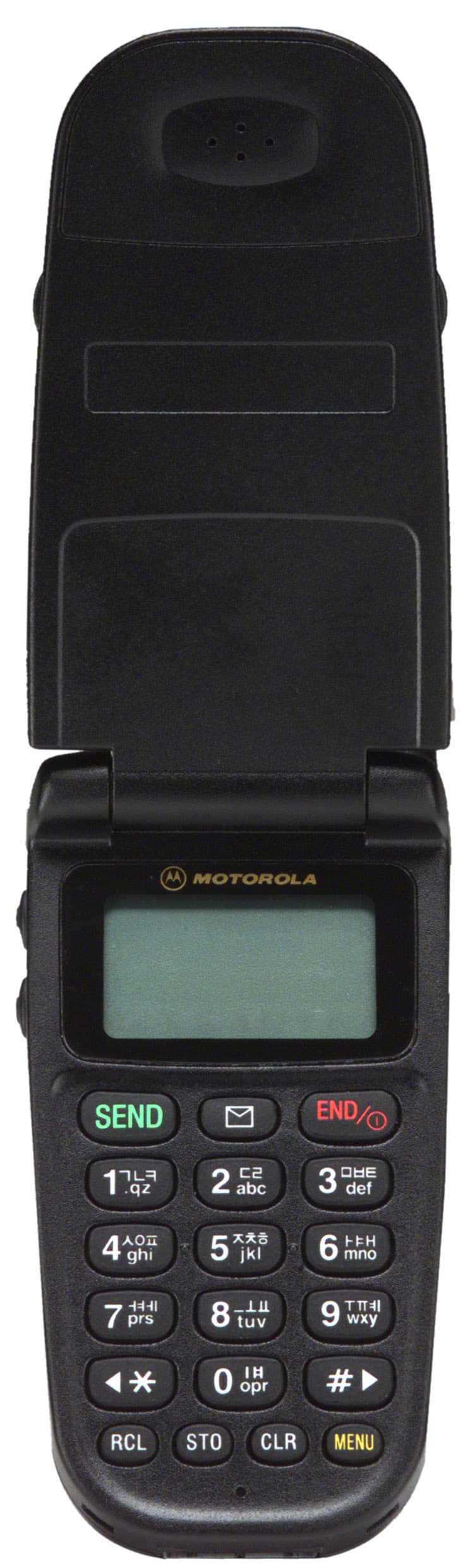
Click to zoom
Application Details
- Equipment Class
- TNE - Licensed Non-Broadcast Transmitter Held to Ear
- Date of Grant
- Mar 22, 2000
- Application Purpose
- Original Equipment
- Date of Application
- Oct 11, 1999
- Equipment Note
- Portable Cellular Transceiver
- Frequency Range
- 824.64000000 - 848.37000000
- Company
- Motorola Mobility LLC
- Country
- United States
Documents & Files
Document Text
Text extracted from the exhibit documents filed with the FCC. Open a document above to read the original.
Users Manual
APPLICANT: MOTOROLAFCC ID: IHDT5ZU1 EXHIBIT 8 A preliminary draft copy of the user manual follows. MC-9100 USER’S MANUAL Contents 1. Summary and electrical performance 1.1 Introduction 1.2 Primary features 1.3 Main functions 1.4 Standard specification 1.5 Safety information 2. Functional Specification and Description 2.1 External appearance & Explanation 2.2 Functional Description of LCD Display 2.3 Effective Usag 1. Summary and electrical performance 1-1. Introduction Motorola digital cellular phone MC-9100 is a very small sized and lightweight mobile station carrying easily which features spectral efficiency, economical efficiency, and low cost based on CDMA(Code Division Multiple Access) technique. CDMA is one of the various multiple access methods, adopting a spread spectrum modulation primarily utilized in military communication equipments in the past for solving the problems like call drop and security in dense residence with a few effective ways such as soft/softer handoff, hard handoff, and dynamic power control. Besides, CDMA can be helpful in enhancing the capacity which is coming big issue as the customer is increased in modern mobile communication by using the frequency reuse technique. CDMA digital cellular network is composed of several components such as MSO(Mobile Switching Office), BSC(Base Station Controller), BTS(Base Station Transmission System), and MS(Mobile Station) and the interface between the mobile station and the base station is designed to be compatible with th standard of the IS-95A in north america and the domestic TTA standard “interface of digital mobile phone in 800 MHz frequency range ”. The related standard with respect to mobile phone is as follows: - IS-95A (Common Air Interface) : regulation of protocol used between the mobile station and the base station - IS-98 : a minimum required standard related to H/W of the mobile station. 1-2. Primary features - Folding type design with very small size - Adoption of EVRC - Korean SMS function loaded. - Adoption of menu/LCD displayed in korea - Excellent call sensitivit - 3 Line display - Refined design with city-life sense 1-3 Main functions - Reception of voice and SMS written b korea - Turbo dial function supported - One touch dial function for international call supported - One touch connection for voice mail supported - Etiquette function - One touch lock supported - Auto-transmit function of the phone number when calling the pager. - Restricted use supported - Alert call, alarm function supported - Bell/ melody/vibration selection function supported - Auto dial of regional number, worldwide clock display supported. - Electronic dial function using memory and pause - Melody download supported - Ear-microphone function supported 1-4. Standard specification The technical specification of MC-9100 digital cellular phone is as follows. ItemsStandardRemarks Type of radio waveG7W Range of operating temp. -20 ~ 50 ° C Tx frequency range824.64 MHz ~ 848.37 MHz Rx frequency range869.64 MHz ~ 893.37 MHz Tx IF frequency130.38 MHz Rx IF frequency85.38 MHz Local frequency range955.02 MHz ~ 978.75 MHz Waveform qualityAbove 0.944 Time response Within ± 1 μ s Reception Sensitivit- 104 dBmwithin FER= 0.5 % Dynamic range-104 ~ - 25 dBmwithin FER= 0.5% Tx power (Max power)320 mw (25 dBm) Tx freq. Offset Within ± 300 Hz Occupied bandwidthBelow 1.32 MHz Conducted spurious ( Tx) 900 kHz, below -42dBc/30kHz 1.98MHz , below -54dBc/30kH Minimum controlled output pwr.Below -50 dBm Open loop control (at –25 dBm) - 48 ± 9. dBm Open loop control (at –65 dBm) - 8 ± 9.5 dBm Open loop control (at –104 dBm)+18 ~ +30 dBm Exterior gauge46mm x 20.2mm x 87mm Exterior gauge with small type battery. 81g Exterior gauge with standard type battery. 88g Power supply 3.6V ± 10% Power supply (based on slot 2 with small type battery) Standby 53 hours Power supply (based on slot 2 with standard type battery) Standby 92 hours Power supply with small type battery 85 minutes. Power supply with standard type battery 165 minutes. * All technical standards not shown above follow the standard of IS-95A and IS-98. 1-5. Safety information Exposure to Radio Frequency Signals Your wireless handheld portable telephone is a low power radio transmitter and receiver. When it is ON, it receives and also sends out radio frequency (RF) signals. International agencies have set standards and recommendations for the protection of public exposure to RF electromagnetic energy. International Commission on Non-Ionizing Radiation Protection (ICNIRP) 1996 Verband Deutscher Elektrotechniker (VDE) DIN-0848 United States Federal Communications Commission, Radio Frequency Exposure Guidelines (1996) National Radiological Protection Board of the United Kingdom, GS 11, 1988 American National Standards Institute (ANSI) IEEE. C95. 1-1992 National Council on Radiation Protection and Measurements (NCRP). Report 86 Department of Health and Welfare Canada. Safety Code 6 These standards are based on extensive scientific review. For example, over 120 scientists, engineers, and physicians from universities, government health agencies, and industry reviewed the available body of research to develop the updated ANSI standard. The design of your phone complies with these standards when used normally. Antenna Care Use only the supplied or an approved replacement antenna. Unauthorized antennas, modifications, or attachments could damage the phone and may violate local agency regulations. Phone Operation Normal Operation Hold the phone as you would any other telephone, with the antenna pointed up and over your shoulder. Tips on Efficient Operation Observe the following guidelines to operate your phone most efficiently. Extend your antenna fully. Do not touch the antenna unnecessarily when the phone is in use. Contact with the antenna affects call quality and may cause the phone to operate at a higher power level than otherwise needed. Batteries CAUTION: All batteries can cause property damage, injur…
Text truncated - open the document above for the full version.
Attestation Statements
APPLICANT: MOTOROLA, INC.FCC ID: IHDT5ZU1 EXHIBIT 2 STATEMENT OF CERTIFICATION The technical data supplied with this application, having been taken under my supervision, is hereby duly certified. The following is a statement of my qualifications: • BSEE 1968 University of Illinois, Chicago • MSEE 1978 Texas A&M University • 23 years experience in wireless radio/cellular telephone design Signature: (signed) NAME: Allen White DATE: 10/06/99 POSITION:Sr. Resource Manager Motorola, Inc. I hereby certify that the above application was prepared under my direction and that to the best of my knowledge and belief, the facts set forth in the application and accompanying technical data are true and correct. Signature: (signed) NAME:Allen White DATE:10/06/99 POSITION:Sr. Resource Manager Motorola, Inc.
Cover Letter(s)
APPLICANT: MOTOROLAFCC ID: IHDT5ZU1 Exhibit 13 October 8, 1999 CONFIDENTIALITY REQUEST CONTAINED WITHIN Federal Communications Commission Authorization and Evaluation Division 7435 Oakland Mills Road Columbia, Maryland 21046 Re: Application for Cellular Transceiver Certification Gentlemen: Application: Motorola, Inc., Pan American Cellular Subscriber Group, 600 N. U.S. Highway 45, Libertyville, Illinois 60048-1286 herein submits: Application for Equipment Authorization (FCC Form 731-October 1992 with integrated Fee Processing Form, Fee Codes EFT and EBC), application fee in the amount of $610, and Exhibits, for Type Acceptance of a Cellular Transceiver; FCC ID: IHDT5ZU1. Motorola is also the manufacturer of this equipment. Confidentiality: Pursuant to Section 0.459 of the Commission's rules (CFR 47), Motorola requests confidentiality for portions of the material contained in this application and that the identified material be withheld from public inspection following the grant of this authorization. This material contains Motorola's trade secrets and confidential information that Motorola does not customarily release to the public and which is otherwise not generally available to the public. Confidentiality is requested for the following exhibits: • Exhibit 4 Block Diagrams • Exhibit 5 Schematics • Exhibit 12 Operational Description Description: This equipment has the capability to operate only in the Digital CDMA standard in the 800 MHz cellular band, as outlined in EIA/TIA IS-95-A "Mobile Station – Base Station Compatibility Standard for Dual-Mode Wideband Spread Spectrum Cellular System”. Technical details for this alternate cellular technology (permitted under the cellular service option provisions in Section 22.901(d) of the Commission's rules) related to Type Acceptance of this equipment, as noted in paragraphs 31 and 32 of the Report and Order in FCC GEN. Docket No. 87-390, are detailed in Exhibit 12. Contact Information: Please contact me by telephone at (847) 523-6167, by facsimile at (847) 523-2350, or by e-mail ([email protected]), if there are any further questions or additional information needed concerning this filing. Regards, Andrew J. Bachler FCC Liaison Cellular Subscriber Sector 600 N. U.S. Highway 45 Libertyville, IL 60048-5343
Cover Letter(s)
APPLICANT: MOTOROLAFCC ID: IHDT5ZU1 Exhibit 13 October 8, 1999 CONFIDENTIALITY REQUEST CONTAINED WITHIN Federal Communications Commission Authorization and Evaluation Division 7435 Oakland Mills Road Columbia, Maryland 21046 Re: Application for Cellular Transceiver Certification Gentlemen: Application: Motorola, Inc., Pan American Cellular Subscriber Group, 600 N. U.S. Highway 45, Libertyville, Illinois 60048-1286 herein submits: Application for Equipment Authorization (FCC Form 731-October 1992 with integrated Fee Processing Form, Fee Codes EFT and EBC), application fee in the amount of $610, and Exhibits, for Type Acceptance of a Cellular Transceiver; FCC ID: IHDT5ZU1. Motorola is also the manufacturer of this equipment. Confidentiality: Pursuant to Section 0.459 of the Commission's rules (CFR 47), Motorola requests confidentiality for portions of the material contained in this application and that the identified material be withheld from public inspection following the grant of this authorization. This material contains Motorola's trade secrets and confidential information that Motorola does not customarily release to the public and which is otherwise not generally available to the public. Confidentiality is requested for the following exhibits: • Exhibit 4 Block Diagrams • Exhibit 5 Schematics • Exhibit 12 Operational Description Description: This equipment has the capability to operate only in the Digital CDMA standard in the 800 MHz cellular band, as outlined in EIA/TIA IS-95-A "Mobile Station – Base Station Compatibility Standard for Dual-Mode Wideband Spread Spectrum Cellular System”. Technical details for this alternate cellular technology (permitted under the cellular service option provisions in Section 22.901(d) of the Commission's rules) related to Type Acceptance of this equipment, as noted in paragraphs 31 and 32 of the Report and Order in FCC GEN. Docket No. 87-390, are detailed in Exhibit 12. Contact Information: Please contact me by telephone at (847) 523-6167, by facsimile at (847) 523-2350, or by e-mail ([email protected]), if there are any further questions or additional information needed concerning this filing. Regards, Andrew J. Bachler FCC Liaison Cellular Subscriber Sector 600 N. U.S. Highway 45 Libertyville, IL 60048-5343
External Photos
APPLICANT: MOTOROLA, INC. FCC ID: IHDT5ZU1 EXHIBIT 3 Front View Rear View
ID Label/Location Info
APPLICANT: MOTOROLAFCC ID: IHDT5ZU1 EXHIBIT 1 FCC IDENTIFICATION (NAMEPLATE) INFORMATION The FCC label shown is the label that will appear on the radio when in production. It will be placed on the outside of the radio telephone. (refer to exhibit 3). FCC ID: IHDT5ZU1
ID Label/Location Info
APPLICANT: MOTOROLAFCC ID: IHDT5ZU1 EXHIBIT 1 FCC IDENTIFICATION (NAMEPLATE) INFORMATION The FCC label shown is the label that will appear on the radio when in production. It will be placed on the outside of the radio telephone. (refer to exhibit 3). FCC ID: IHDT5ZU1
Internal Photos
APPLICANT: MOTOROLA, INC. FCC ID: IHDT5ZU1 EXHIBIT 9 Front View Rear View
Parts List/Tune Up Info
APPLICANT: MOTOROLA, INC.FCC ID: IHDT5ZU1 TRANSCEIVER ADJUSTMENTS/TUNE-UP PROCEDURE EXHIBIT 10 There are no user accessible adjustments or tuning in this portable cellular transceiver. All necessary adjustments and tuning are performed during manufacture of the product. Any adjustments or tuning after service or repair are done as part of that process as special equipment is required to perform such adjustments.
RF Exposure Info
P P a a g g e e 1 1 October 1, 1999 SAR Test Report for Motorola portable cellular phone (FCC ID IHDT6ZU1). Prepared by: Paul Moller, Principal Staff Engineer Motorola Personal Communications Sector Product Safety Laboratory Libertyville, Illinois Contents 1) Introduction 2) Applicable Regulations 3) Description of Test Sample 4) Description of Motorola SAR Test Facility 5) Test Sample Conditions 6) Method of Measurement 7) Measurement Uncertainty 8) SAR Test Results 9) Hand SAR 10) Body Worn Configuration Evaluation 11) External Antenna Option Evaluation 12) Battery Options 13) Summary Appendix A: Included data from Measurements Against Phantom Head Appendix B: Measurement Probe Calibration Certificate Appendix C: Printout from the Dasy measurement system validation test Appendix D: Dasy Users Manual (First page) P P a a g g e e 2 2 1. Introduction The Motorola Personal Communications Sector Product Safety Laboratory has performed measurements of the maximum potential exposure to the user of portable cellular phone FCC ID IHDT6ZU1. The Specific Absorption Rate (SAR) of this product was measured. This report details the test setup and equipment as well as the results of those tests. 2. Applicable Regulations Federal Communications Commission rule §2.1093(d)(2), the ANSI/IEEE C95.1 1992 and the NCRP Report Number 86 specify the maximum exposure limit of 1.6 W/kg as averaged over any 1 gram of tissue for portable devices being used within 20cm of the user in the uncontrolled environment. 3. Description of Test Sample A prototype unit serial number 061899-1 was measured. This unit is identical in physical construction, maximum radiated power levels and antenna structure to units that will be in production. It transmits in the frequency range of 824 to 849 MHz using CDMA mode only. The maximum average transmit power for this test unit is 0.25 Watts. The unit is equipped with a telescoping antenna that serves as both a receive and transmit antenna. The antenna has a retracted and an extended operating position as shown in figures 1 and 2 respectively. Figure 1. Front of Phone with Antenna Figure 2. Back of Phone with Antenna Retracted. Extended. Figures 3 and 4 show the test unit as it is placed onto the phantom head with the antenna in the retracted and extended positions respectively. For the purposes of the actual SAR tests the phantom head is tilted on its side by 90 degrees so that a vertically oriented measurement P P a a g g e e 3 3 probe can easily scan an area where the phone is in close contact with the phantom and the SAR will be the highest. Figure 3. Phone against Phantom Head with Antenna Retracted Figure 4. Phone against Phantom Head with Antenna Extended P P a a g g e e 4 4 4. SAR Test Facility The Motorola test facility utilized for the SAR testing of this product is the Personal Communications Sector Product Safety Laboratory, in Libertyville Illinois. The laboratory utilizes a Dosimetric Assessment System (Dasy™) SAR measurement system manufactured by Schmid & Partner Engineering AG (SPEAG™), of Zurich Switzerland. This system utilizes a computer controlled six axis robot to move a measurement probe to measure the SAR. A photo of the Dasy system with the Motorola phantom is shown in figure 5 Probe serial number 1103 was used for the measurements. It was calibrated at SPEAG™, and has a calibration date April 20, 1999. A copy of the calibration certificate is included as appendix B. Dipole Validation Kit type D900V2, serial number 036 was used to validate the system accuracy at 900MHz. The validation SAR value is 9.56 mW/g normalized to 1 Watt, and the Dasy system used for the test phone measured 9.40 mW/g normalized to 1 Watt. This is within the required accuracy, and thus the measured SAR values are considered correct for the 900 MHz frequency band. See appendix C for printout of the validation test from the Dasy measurement system. The measurement methodology is described in IEEE Transactions on Vehicular Technology, vol. 44, no. 3, August 1995, titled Electromagnetic Energy Exposure of Simulated users of Portable Cellular Telephones. The Dasy system is operated per the instructions in the Dasy Users Manual. A copy of the title page of this manual is included as appendix D. The entire manual is available directly from SPEAG. Figure 5. Dasy system with the Motorola Phantom. P P a a g g e e 5 5 5. Test Sample Conditions For the purposes of these tests the subject phone was positioned on the measurement phantom per the instructions in the Motorola users manual for the subject phone. The position used for the tests is the 3-point contact position. In this position the test sample contacts the phantom’s ear and cheek and is positioned with a repeatability of better than ±6%. Since the antenna is not located on the center of the phone, the SAR was measured with the phone on both the left and right side talk positions (See figures 3 and 4). Due to the construction of the phone, the base of the antenna is 20 mm away from the phantom for the left side head, which is the closest. The test sample is capable of operation in a test mode that allows control of the transmitter without the need to place actual phone calls. This guarantees that the unit does not change its transmitter power, and that the resultant SAR values will not be affected by external connections. For the purposes of this test the unit is commanded to test mode and manually set to the proper channel, transmitter power level and transmit mode of operation. The phone is then placed in the SAR measurement system with a fully charged extended capacity battery. At the end of each test the unit is measured for RF power out so as to ensure that the test was evaluating the maximum SAR level. For the purposes of these tests, the transmitter was operated at the highest transmitter output level in both the analog and digital modes (full vocoder rate for digital mode), with the antenna in both the extended and retracted…
Text truncated - open the document above for the full version.
RF Exposure Info
To: Kwok Chan, FCC cc: Steve Hauswirth From: Paul Moller, Motorola, Inc. Andy Bachler Subject: FCC ID IHDT6ZU1 Body Worn Configuration SAR Date: February 10, 2000 The cellular phone (FCC ID IHDT6ZU1) can be used in a body-worn configuration using the supplied belt clip. We have performed an evaluation to show RF exposure compliance when used the supplied belt clip. Figure 1 shows the test unit as it is placed onto the phantom. The phantom was filled with a liquid having relative dielectric constant equal to 51.9 and conductivity equal to 1.1 S/m at 835MHz. The composition of the liquid mixture is as follows: 52.5% water; 45.0% sugar; 1.3% salt, 1% HEC; and 0.2% bactericide. Figure 1. Phone In Supplied Belt Clip Against Phantom The following table shows the SAR values for the body worn condition for using the supplied belt clip. A full data set output of the test condition with the highest SAR values from the Dasy™ measurement system is included as appendix A. The test conditions included are indicated as bold numbers in the following table. All other test conditions measured lower SAR values than those included. The location of highest SAR was the area on the phone near the antenna. . Belt Clip Channel Ant Ret Ant Ext 991 0.20 0.56 384 0.35 0.37 799 0.36 0.32
RF Exposure Info
APPLICANT: MOTOROLAFCC ID: IHDT5ZU1 Exhibit 13A February 21, 2000 RESPONSE TO SAR QUESTIONS (Correspondence Reference Number:11297) Federal Communications Commission Authorization and Evaluation Division 7435 Oakland Mills Road Columbia, Maryland 21046 Re: Application for Cellular/PCS Transceiver Certification (EA95638) Kwok Chan & Joe Dichoso: Purpose: This document responds to questions on the submission for the IHDT5ZU1 (EA95638) application. Description: To facilitate the response to SAR questions, the following includes the original text and the highlighted response. From:Joe Dichoso [email protected] FCC Application Processing Branch Re:FCC ID IHDT5ZU1 Applicant:Motorola Inc Correspondence Reference Number:11297 731 Confirmation Number:EA95638 Date of Original E-Mail:01/04/2000 Please submit the reply to the following issues in the RF exposure info folder of the electronic file. Contact Kwok Chan at [email protected] if you have any questions and send him an e-mail when you download the information. Motorola, EA 95638 - 1. The users manual indicates this phone has a ear-microphone jack which may allow body-worn configurations using third-party accessories where SAR compliance cannot be ensured. The SAR report indicates this device is not shipped with any belt-clip or holster. Since SAR compliance for body-worn configurations has not been tested, it must be clearly indicated to users that device operations with third-party accessories for body-worn operations have not been tested and may not comply with SAR limit. Users must be cautioned to avoid operating the phone with a headset for body-worn configurations using non-tested belt-clips, holsters and similar accessories or placing the phone in pockets while it is transmitting. Response: The IHDT5ZU1 product now includes a tested belt clip device. A supplemental SAR report has been submitted. 2. Alternatively, Motorola may choose to perform SAR tests to determine a minimum or acceptable separation distance to comply with SAR limit for body-worn operations using an air spacing between the back of the phone and the phantom. This will allow certain generic belt-clips and holsters without any metallic components, that can provide the minimum separation to be used with this phone for body-worn use. In this case, users must be cautioned about the minimum separation distance requirement for body-worn operations using generic belt-clips and holsters that do not contain any metallic component for satisfying RF exposure requirements, and body-worn operating configurations that do not satisfy these requirements may not comply with SAR limit and should be avoid. Response: See #1 above. APPLICANT: MOTOROLAFCC ID: IHDT5ZU1 Exhibit 13A 3. Depending on choices of item #1 and #2 above, please revise manual to include the appropriate caution statement at a location in the manual that will be obvious to users. The statement should indicate the requirements are for FCC RF exposure compliance. Response: The following is a part of the updated users manual safety information: Safety Information IMPORTANT: Read this information before using your wireless handheld phone. Exposure to Radio Frequency Signals Your wireless handheld portable telephone is a low power radio transmitter and receiver. When it is ON, it receives and also sends out radio frequency (RF) signals. In August 1996, The Federal Communications Commission (FCC) adopted RF exposure guidelines with safety levels for handheld wireless phones. Those guidelines are consistent with safety standards previously set by both U.S. and international standards bodies: • American National Standards Institute (ANSI) IEEE. C95. 1-1992 • National Council on Radiation Protection and Measurement (NCRP). Report 86 • International Commission on Non-Ionizing Radiation Protection (ICNIRP) 1996 • Ministry of Health (Canada), Safety Code 6 Those standards were based on comprehensive and periodic evaluations of the relevant scientific literature. For example, over 120 scientists, engineers, and physicians from universities, government health agencies, and industry reviewed the available body of research to develop the ANSI Standard (C95.1). The design of your phone complies with the FCC guidelines (and those standards). For additional information concerning exposure to radio frequency signals, see the statement by the FDA at the end of this user guide. To maintain compliance with FCC RF exposure guidelines, if you wear a handset on your body, use the Motorola- supplied or approved carrying case, holster, or other body-worn accessory. If you do not use a body-worn accessory, ensure the antenna is at least one inch (2.5 centimeters) from your body when transmitting. Use ofnon-Motorola accessories may violate FCC RF exposure guidelines. Antenna Care Use only the supplied or an approved replacement antenna. Unauthorized antennas, modifications, or attachments could damage the phone and may violate FCC regulations. 4. FYI - Section 5 of SAR report has analog and digital mode. This phone does not have analog mode. 5. FYI - Section 7 of SAR report indicates RMS, which should be root-sum-square. The numbers provided are root- sum-square. Note: Maximum measured ERP is 255 mW, requesting for 250 mW ERP. Maximum conducted output is 288 mW, SAR performed at 260 mW (assume conducted). Output on grant should not exceed 250 mW ERP. Additional grant comments may apply for body-worn operations. Kwok Chan Contact Information: Thank you for this special consideration. Please contact me by telephone at (847) 523-6167, by facsimile at (847) 523-2350, or by e-mail ([email protected]), if there are questions or additional information needed concerning this filing. Regards, Andrew J. Bachler FCC Liaison Cellular Subscriber Sector 600 N. U.S. Highway 45 Libertyville, IL 60048-5343
Test Report
APPLICANT: MOTOROLA, INCTRANSCEIVER TYPE: IHDT5ZU1 EXHIBIT 6 Submitted Measured Data Index ExhibitDescription 6ARF Power Output – Measured Data 6FOccupied Bandwidth in the CDMA Digital Mode 6GConducted Spurious and Harmonic Emission 6HRadiated Spurious and Harmonic Emission 6JFrequency Change vs. Temperature 6KFrequency Change vs. Supply Voltage 6LMeasurement Techniques APPLICANT: MOTOROLA, INCTRANSCEIVER TYPE: IHDT5ZU1 EXHIBIT 6A RF Power Output Data The input supply to the transmitter is set at 3.6 volts. The RF power output was measured with the indicated voltage and current applied into the final RF amplifying device. Conducted RF Power This phone operates in the CDMA mode. The values measured for RF Output, DC Current and RF Input Power are all average values which reflect a 100% transmit duty cycle in CDMA operation. Measured RF Output Power: 0.288 W (24.6 dBm) Measured DC Voltage: 3.6 V Measured DC Current: 635mA Measured RF input: 0.63 mW (-2 dBm Effective Radiated Power: Since the phone is intended for use with a provided antenna (and non-standard RF connector), ERP is measured. The dipole antenna substitution method was used. The result indicated is the maximum ERP found over the channels and radio orientations tested. The maximum was found in transmitting mode with the antenna in the extended position. The input supply to the transmitter was set at 3.6 Volts. Maximum Effective Radiated Power (Relative to Half-Wavelength Dipole): 0.255 W (24.06 dBm) APPLICANT: MOTOROLA, INCTRANSCEIVER TYPE: IHDT5ZU1 EXHIBIT 6F Occupied Bandwidth in the CDMA Digital Mode 1. Spurious emission level : Modulate the transmitter with OQPSK modulation, using pseudo random data. Obtain image on spectrum analyzer. (Refer to IS98A, 10.4.2.1) Deviation of the Carrier with OQPSK Modulation Horizontal Scale = 0.62 MHz/Division Vertical Scale = 10 dB/Division(Attenuation) Resolution Bandwidth =30 kHz Power Level = 0.288 W (24.6 dBm)(Average power in transmitter) Measured Data: Comments: Spurious emission level for frequency offset at greater than 885 kHz shall be at least –42 dBc/30kHz and level for frequency offset at greater than 1.98MHz shall be at least –54 dBc/30kHz. APPLICANT: MOTOROLA, INCTRANSCEIVER TYPE: IHDT5ZU1 EXHIBIT 6F 2. Occupied Bandwidth should be less than 1.32 MHz. Deviation of the Carrier with OQPSK Modulation Horizontal Scale = 0.3 MHz/Division Vertical Scale = 10 dB/Division(Attenuation) Resolution Bandwidth =30 kHz Occupied BW [99.00%] = 1.275 MHz Measured Data: APPLICANT: MOTOROLA, INCTRANSCEIVER TYPE: IHDT5ZU1 EXHIBIT 6G Conducted Spurious and Harmonic Emission 1. Transmitter Conducted Spurious Emission Carrier Power: 0.065 mW (-12 dBm) Carrier Frequency: low(ch#=1011), mid(ch#=363), high(ch#=779) in 824.04 to 848.97 MHz * Each reported emission reflects the highest absolute level found among all power levels, channels, and power amplifier configuration tested. * All emissions not reported are more 20 dB below the FCC specification. * Spectrum was searched from 30 kHz to the 10 th harmonic of the transmitter. ** Spurious Emission Limits when transmitting in CDMA mode (IS-98A, 10.5.1) For Frequency Offset ∆f, with∆f Greater than 885.0 kHzGreater than 1.98 MHz (a) –42dBc/30 kHz(a) –54dBc/30 kHzSpurious Emission levels shall be less than either (a), or both (b) and (c) (b) –60dBm/30 kHz (c) –54dBm/1.23MHz (b) –60dBm/30 kHz (c) –54dBm/1.23MHz Transmitter Conducted Spurious Emissions -10-8-6-4-20246810122345678910 Frequency Spurious Level (dBm) Spec Margin = -37.8 dBc PTX=-12 dBm Frequency from Carrier (MHz)Harmonics SPEC. Limit = -49.8 dBm APPLICANT: MOTOROLA, INCTRANSCEIVER TYPE: IHDT5ZU1 EXHIBIT 6H Radiated Spurious and Harmonic Emission -60 -50 -40 -30 -20 -10 0 10 20 30 -6-4-202462345678 frequency from carrierfrequencyharmonic of carrier -38 specification limit :43 + 10 log (carrier power) = -13.00 dBm Transmit = 24.2 dBm, carrier spuri ous leve l (dBm) Transmitter conducted spurious emissions 9 10 -26 -39 -38 APPLICANT: MOTOROLA, INCTRANSCEIVER TYPE: IHDT5ZU1 EXHIBIT 6J Frequency Change vs. Temperature * Each reported frequency deviation reflects the highest absolute levels found among several condition. Frequency Vs. Temperature Temperature [Degrees] Frequency Variation [Hz] APPLICANT: MOTOROLA, INCTRANSCEIVER TYPE: IHDT5ZU1 EXHIBIT 6K Frequency Change vs. Voltage * Each reported frequency deviation reflects the hi…
Text truncated - open the document above for the full version.
Contact Information
Applicant
Jeff Narducci(Director Product Compliance)
Technical Specifications
| # | Rule Parts | Frequency Range | Power Output | Emission | Tolerance |
|---|---|---|---|---|---|
| 1 | 22.901(d) | 824.64 MHz - 848.37 MHz | 250.00 mW | 1M25F9W | 300.0000000000 Hz |
Other Applications from Motorola Mobility LLC
IHDT56AW9
May 12, 2026Smart Watch
Equipment Class
NII - Unlicensed National Information Infrastructure TXIHDT56AW5
Apr 08, 2026Mobile Cellular Phone
Equipment Class
DTS - Digital Transmission SystemIHDT56AW6
Mar 18, 2026Smart Watch
Equipment Class
JBP - Part 15 Class B Computing Device PeripheralIHDT56AX4
Mar 17, 2026Mobile Cellular Phone
Equipment Class
PCE - PCS Licensed Transmitter held to earIHDT56AW3
Mar 03, 2026Mobile Cellular Phone
Equipment Class
6XD - 15E 6 GHz Low Power Indoor Client