IHDT5ZW1Portable Cellular Transceiver
Motorola Mobility LLC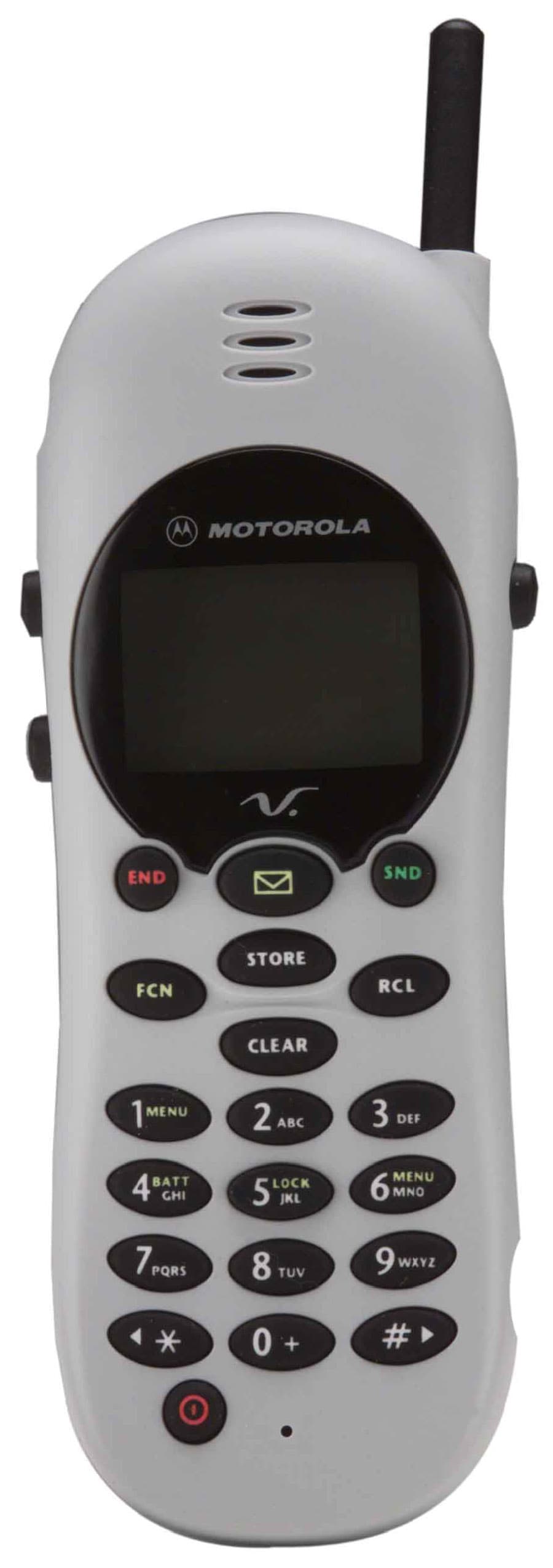
Click to zoom
Application Details
- Equipment Class
- TNE - Licensed Non-Broadcast Transmitter Held to Ear
- Date of Grant
- May 02, 2000
- Application Purpose
- Original Equipment
- Date of Application
- Feb 21, 2000
- Equipment Note
- Portable Cellular Transceiver
- Frequency Range
- 824.00000000 - 849.00000000
- Company
- Motorola Mobility LLC
- Country
- United States
Documents & Files
Document Text
Text extracted from the exhibit documents filed with the FCC. Open a document above to read the original.
Users Manual
APPLICANT: MOTOROLA, INC.FCC ID: IHDT5ZW1 EXHIBIT 8 INSTRUCTION MANUAL A preliminary draft copy of the Users Manual follows: Introduction 1 English Introduction Welcome Thank you for choosing your Motorola phone from a global leader in communications technology. All Motorola digital cellular phones are designed and manufactured to meet Motorola’s rigorous specifications and world-class quality standards. During development, our laboratory testing team took your cellular phone through rigorous durability tests including temperature, humidity, shock, dust, vibration, and drop tests-and the phone still worked! We are confident that the phone you purchased will meet your own exacting standards. Enjoy your Motorola phone. m3cd_us.bk : intro.fm5 Page 1 Wednesday, March 1, 2000 11:30 AM Introduction 2 English Understanding this Manual Many of your phone options are accessed by a simple menu system. A full description of the menus and how to move around them is covered in the next section Menu Navigation . When the manual describes the use of each menu item, it will be assumed that you are familiar with the menu system. Key Presses Key presses are represented in this manual using symbols so that you may locate and use the required sequence quickly. A sequence of key presses may be shown as follows:ƒ ‚ 7 DThis means you should press ƒ followed by ‚ , 7 , and then D , in sequence, not simultaneously. Prompts and Messages Your phone responds to key presses by displaying either easy to understand prompts that guide you to the next action, or simple messages confirming that your action is complete. Prompts and messages are represented in this manual in LCD style, for example:Enter 1st Letter or Location ___ Other Symbols You will find the following symbols used throughout this manual:A A Note contains additional information which is relevant to the feature/item. ! A Caution contains important additional information which is relevant to the efficient and/or safe usage of your phone. i This symbol indicates a short key sequence for the feature. m3cd_us.bk : intro.fm5 Page 2 Wednesday, March 1, 2000 11:30 AM Introduction 3 English Menu Navigation A large number of your phone's options are accessed by using menus which use a common approach for selection, change and cancellation.Please read this section carefully before attempting to access a menu option. When you understand the common approach to menu navigation and how the menus are shown on the page, you will be able to access and change options with ease. Menus and Sub-menus A menu is a simple list of options. Some of these options provide access to a further list of options called a sub-menu. When navigating through the menus you may find it is helpful to think in terms of menu levels - the ‘parent’ menu being on one level and its sub-menus being on a lower level. Entering the Menus Press ƒ then press ⁄ or the Smart Button ( A ) to enter the menu system. Navigating the Menus You can navigate through the menu system using the volume keys located on the left side of the phone and the Smart Button ( A ) located on the right side of the phone. Use the upper and lower volume keys to scroll to sub-menus. Use the Smart Button to choose menus and functions.Follow these symbols as a guide for using the keys on the side of your phone: Press q to scroll up. Press Z to scroll down. Press a to select. You can also use your phone’s « and » keys to scroll through the menu system. Leaving the Menus Press º to exit the menu. Menu Options with Security Codes Some options are protected from misuse by requiring you to enter one of the security codes. To use these options, you must enter the requested code before proceeding. m3cd_us.bk : intro.fm5 Page 3 Wednesday, March 1, 2000 11:30 AM Introduction 4 English Total Customer Satisfaction At Motorola, Total Customer Satisfaction is a top priority. If you have a question, a suggestion or a concern about your Motorola Cellular Phone, Motorola wants to hear from you.Please contact the Motorola Cellular Response Center by calling one of the local phone numbers in the following countries:Austria 0800 297246Belgium 0800 72 370 Czech Republic 00420 2 21 85 21 01 Denmark 4348 8005Egypt 02 3411800Eire 01 402 6887 Finland 0800 117 036 France 0 803 303 302 Germany 0180 35050Greece 00800 441 28150 Italy 02 696 333 16 Jordan 06 863750Kuwait 484 2000 Ext 1177 Lebanon 01 744156Luxembourg 0800 21 99 Netherlands 0800 022 27 43 Norway 22 55 10 04 Oman 790925Portugal 21 318 0051 Qatar 418999 Saudi Arabia 01 2303294 South Africa 0800 11 48 49 Spain 902 100 077Sweden 08 445 1210 Switzerland 0800 553 109 Turkey 0212 425 9090 UK 0500 55 55 55 United Arab Emirates 04 32 11 66 Hong Kong 852 25063888 People’s Republic of China 86 10 68466060Singapore 65 4855 333 Taiwan 886 2 87731746 United States of America 1 800 331 6456 Canada 1 800 461 4575 For e-mail questions contact:[email protected] Internet questions contact:http://www.motorola.com m3cd_us.bk : intro.fm5 Page 4 Wednesday, March 1, 2000 11:30 AM Contents 5 English Contents Safety Important information for the efficient and safe operation of your phone ....................................................... .........................7 About Your Phone and Battery Introduces your phone, explains how to charge and maintain batteries........................................................... ........................13 Using Your Phone Explains how to place calls, how to redial, how to end a call, and how to use the phone memory ................................. ......21 Using the Menu Features Provides an explanation of the Menu Features and how to use them............................................................... ........................31 Using the Messaging Menu Provides an explanation of the Messaging Menu and how to use it ................................................................ .........................57 Using the MiniBrowser Provides an explanation of the MiniBrowser …
Text truncated - open the document above for the full version.
Attestation Statements
APPLICANT : MOTOROLA, INC. FCC ID : IHDT5ZW1 EXHIBIT 2A February 22, 2000 SPECIFICATION COMPLIANCE STATEMENT Engineer-in-Charge Equipment Authorization Branch Federal Communications Commission We hereby certify that this transmit and receive equipment (FCC ID : IHDT5ZW1) for dual mode mobile station cellular use is capable of compliance with July 1996 TIA/EIA-95-A, Mobile Station-Base Station Compatibility Standard for Dual-Mode Wide Band Spread Spectrum Cellular Systems, and with OET bulletin No. 53 “Cellular System Mobile Station – Land Station Compatibility Specification”. (Signed Michael Kuksuk) Michael Kuksuk Engineering Section Manager Cellular Subscriber Equipment (Signed Ralph Smallwood) Ralph Smallwood Engineering Manager Cellular Subscriber Equipment APPLICANT : MOTOROLA, INC. FCC ID : IHDT5ZW1 EXHIBIT 2B STATEMENT OF CERTIFICATION The technical data supplied with this application, having been taken under my supervision is hereby duly certified. The following is a statement of my qualifications: 11 years RF Design Experience SIGATURE: (signed) Michael Kuksuk NAME: Michael Kuksuk DATE: February, 20, 2000 POSITION: Engineering Section Manager I hereby certify that the above application was prepared under my direction and that to the best of my knowledge and belief, the facts set forth in the application and accompanying technical data are true and correct: SIGNATURE: (signed) Ralph Smallwood NAME: Ralph Smallwood DATE: February 20, 2000 POSITION: Engineering Manager
Cover Letter(s)
APPLICANT: MOTOROLAFCC ID: IHDT5ZW1 Exhibit 13 February 25, 2000 CONFIDENTIALITY REQUEST CONTAINED WITHIN Federal Communications Commission Authorization and Evaluation Division 7435 Oakland Mills Road Columbia, Maryland 21046 Re: Application for Cellular/PCS Transceiver Certification Gentlemen: Application: Motorola, Inc., Personal Communications Sector, 600 N. U.S. Highway 45, Libertyville, Illinois 60048-1286 herein submits: Application for Equipment Authorization (FCC Form 731-October 1992 with integrated Fee Processing Form, Fee Codes EFT and EBC), application fee in the amount of $610, and Exhibits; for Certification of a Cellular Transceiver, FCC ID: IHDT5ZW1. Motorola is also the manufacturer of this equipment. Confidentiality: Pursuant to Section 0.459 of the Commission's rules (CFR 47), Motorola requests confidentiality for portions of the material contained in this application and that the identified material be withheld from public inspection following the grant of this authorization. This material contains Motorola's trade secrets and confidential information that Motorola does not customarily release to the public and which is otherwise not generally available to the public. Confidentiality is requested for the following exhibits: • Exhibit 4 Block Diagrams • Exhibit 5 Schematics • Exhibit 12 Operational Description Description: This equipment has the capability to operate in both the conventional Analog Cellular standard and the Digital CDMA standard in the 800 MHz cellular band, as outlined in EIA/TIA IS-95-A "Mobile Station – Base Station Compatibility Standard for Dual-Mode Wideband Spread Spectrum Cellular System”. Technical details for this alternate cellular technology (permitted under the cellular service option provisions in Section 22.933 of the Commission's rules) related to Type Acceptance of this equipment, as noted in paragraphs 31 and 32 of the Report and Order in FCC GEN. Docket No. 87-390, are detailed in Exhibit 12. Contact Information: Please contact me by telephone at (847) 523-6167, by facsimile at (847) 523-2350, or by e-mail ([email protected]), if there are questions or additional information needed concerning this filing. Regards, Andrew J. Bachler FCC Liaison Cellular Subscriber Sector 600 N. U.S. Highway 45 Libertyville, IL 60048-5343
External Photos
APPLICANT: MOTOROLA, INC. FCC ID: IHDT5ZW1 EXHIBIT 3 Front View Back View Antenna Extended (Battery Removed to Show Equipment ID)
ID Label/Location Info
APPLICANT: MOTOROLA,INC FCC ID: IHDT5ZW1 EXHIBIT 1 FCC IDENTIFICATION (NAMEPLATE) INFORMATION The FCC label shown is representative of the label that will appear on the radio when in production. It will be placed on the radio telephone as shown in Exhibit 3. Other information may also be included on this label. FCC I D : IHDT5ZW1
Internal Photos
APPLICANT: MOTOROLA, INC. FCC ID: IHDT5ZW1 EXHIBIT 9 Front View (Shields Removed) Rear View (Shields Removed)
Parts List/Tune Up Info
APPLICANT: MOTOROLA, INC.FCC ID : IHDT5ZW1 EXHIBIT 10 Transceiver Adjustments/Tune-Up Procedure There are no user accessible adjustments or tuning in this portable cellular transceiver. All necessary adjustments and tuning are performed during manufacture of the product. Any adjustments or tuning after service or repair are done as part of that process as special equipment is required to perform such adjustments.
RF Exposure Info
February 23, 2000 SAR Test Report for Motorola portable cellular phone (FCC ID IHDT5ZW1). Prepared by: Paul Moller, Principal Staff Engineer Motorola Personal Communications Sector Product Safety Laboratory Libertyville, Illinois Contents 1) Introduction 2) Applicable Regulations 3) Description of Test Sample 4) Description of Motorola SAR Test Facility 5) Test Sample Conditions 6) Method of Measurement 7) Measurement Uncertainty 8) SAR Test Results 9) Body Worn Configuration 10) Battery Options 11) Summary Appendix A: Included data Appendix B: Included body worn data Appendix C: Printout from the Dasy™ measurement system validation test P P a a g g e e 2 2 1. Introduction The Motorola Personal Communications Sector Product Safety Laboratory has performed measurements of the maximum potential exposure to the user of portable cellular phone FCC ID IHDT5ZW1. The Specific Absorption Rate (SAR) of this product was measured. This report details the test setup and equipment as well as the results of those tests. 2. Applicable Regulations Federal Communications Commission rule §2.1093(d)(2), the ANSI/IEEE C95.1 1992 and the NCRP Report Number 86 specify the maximum exposure limit of 1.6 W/kg as averaged over any 1 gram of tissue for portable devices being used within 20cm of the user in the uncontrolled environment. 3. Description of Test Sample A prototype unit serial number EDD1B346 was measured. This unit is identical in physical construction, maximum radiated power levels and antenna structure to units that will be in production. It transmits in the frequency range of 824 to 849 MHz using AMPS mode and CDMA mode. The unit was tested at its maximum transmitter power. The unit is equipped with a telescoping antenna that serves as both a receive and transmit antenna. The antenna has a retracted and an extended operating position as shown in figures 1 and 2 respectively. Figure 1. Side of Phone with Figure 2. Side of Phone with Antenna Retracted Antenna Extended P P a a g g e e 3 3 Figures 3 and 4 show the test unit as it is placed onto the Motorola phantom. For the purposes of the actual SAR tests the Motorola phantom head is tilted on its side by 90 degrees so that a vertically oriented measurement probe can easily scan an area where the phone is in close contact with the phantom and the SAR will be the highest. Figure 3. Phone against side of Phantom Head with Antenna Retracted P P a a g g e e 4 4 Figure 4. Phone against side of Phantom Head with Antenna Extended 4. SAR Test Facility The Motorola test facility utilized for the SAR testing of this product is the Personal Communications Sector Product Safety Laboratory, in Libertyville Illinois. The laboratory utilizes a Dosimetric Assessment System (Dasy™) SAR measurement system manufactured by Schmid & Partner Engineering AG (SPEAG™), of Zurich Switzerland. This system utilizes a computer controlled six axis robot to move a measurement probe to measure the SAR. A photo of the Dasy™ system with the Motorola phantom is shown in figure 5. Probe serial number 1508 was used for the measurements. It was calibrated at SPEAG™, and has a calibration date of October 28,1999. A copy of the calibration certificate is included as appendix C. Dipole Validation Kit type D900V2, serial number 063 was used to validate the system accuracy. The validation SAR value is 9.56 mW/g normalized to 1 Watt, and the Dasy™ system used for the test phone measured 9.36 mW/g normalized to 1 Watt. This is within the required accuracy, and thus the measured SAR values are considered correct. See appendix C for printout of the validation test from the Dasy™ measurement system. The measurement methodology is described in IEEE Transactions on Vehicular Technology, vol. 44, no. 3, August 1995, titled Electromagnetic Energy Exposure of Simulated users of P P a a g g e e 5 5 Portable Cellular Telephones. The Dasy™ system is operated per the instructions in the Dasy™ Users Manual. The entire manual is available directly from SPEAG™. Figure 5. Dasy™ System 5. Test Sample Conditions For the purposes of these tests the subject phone was positioned on the measurement phantom per the instructions in the Motorola users manual for the subject phone. The position used for the tests is the 3-point contact position. In this position the test sample contacts the phantom’s ear and cheek and is positioned with a repeatability of better than ±6%. Since the antenna is not located on the center of the phone, the SAR was measured with the phone on both the left and right side talk positions (See figures 3 and 4). Due to the construction of the phone, the base of the antenna is 26 mm away from the phantom for the left side head, which is the closest. The test sample is capable of operation in a test mode that allows control of the transmitter without the need to place actual phone calls. This guarantees that the unit does not change its transmitter power, and that the resultant SAR values will not be affected by external connections. For the purposes of Analog mode tests the unit is commanded to test mode and P P a a g g e e 6 6 manually set to the proper channel, transmitter power level and transmit mode of operation. For the purposes of the CDMA mode tests, the unit is placed in a phone call using an HP8924 and is commanded to the highest possible power by means of the “always up” command. The phone is then placed in the SAR measurement system with a fully charged battery. At the end of each test the Dasy™ system measures the drift of the SAR at a fixed point in the phantom so as to ensure that the test sample has not changed in transmitter power. For the purposes of these tests, the transmitter was operated at the highest transmitter output and with the phone and module on both left and right side talk positions. 6. Method of Measurement The system is instructed to scan as much of the face of the phone as is in close proximity to the phantom. Using the information gained about the general region …
Text truncated - open the document above for the full version.
RF Exposure Info
April 11, 2000 Supplement to SAR Test Report for Motorola portable cellular phone (FCC ID IHDT5ZW1). Prepared by: Paul Moller, Principal Staff Engineer Motorola Personal Communications Sector Product Safety Laboratory Libertyville, Illinois Contents 1) Summary of FCC request for additional information 2) Location of Peak SAR with Respect to Phone in Body Worn Condition 3) Separation Distance between Back of Phone and Body Phantom 1. Summary of FCC request for additional information There was a request for additional information regarding Motorola’s SAR Test Report for Motorola portable cellular phone (FCC ID IHDT5ZW1) dated February 23, 2000. The requested information may be summarized as follows: Please identify the peak SAR location with respect to the phone for the antenna IN and OUT configurations for body-worn SAR, and identify the minimum separation distance between the extended antenna and the body phantom. 2. Location of Peak SAR with Respect to Phone in Body Worn Condition The location of peak SAR when the phone is in the supplied belt-clip for PCS band is shown in figure 1 and figure 2. Figure 1. Body-worn contour plot overlaid on the back of the phone with Antenna Extended Figure 2. Body-worn contour plot overlaid on the back of the phone with Antenna Retracted 3. Separation Distance between Back of Phone and Body Phantom The separation distance provided by the belt-clip between the back of the phone and the body phantom, and the closest point between the antenna and the phantom is shown in figure 3 and figure 4. Figure 3. Separation Distances Provided by Belt-Clip with Antenna Extended Figure 4. Separation Distances Provided by Belt-Clip with Antenna Retracted
RF Exposure Info
APPLICANT: MOTOROLAFCC ID: IHDT5ZW1 Exhibit 11A April 13, 2000 RESPONSE TO SAR QUESTIONS (Correspondence Reference Number:13104) Federal Communications Commission Authorization and Evaluation Division 7435 Oakland Mills Road Columbia, Maryland 21046 Re: Application for Cellular/PCS Transceiver Certification (EA96830) Kwok Chan &: Frank Coperich Purpose: This document responds to questions on the submission for the IHDT5ZW1 (EA96830) application. Description: To facilitate the response to SAR questions, the following includes the original text and the highlighted response. From:Frank Coperich [email protected] FCC Application Processing Branch Re:FCC ID IHDT5ZW1 Applicant:Motorola Inc Correspondence Reference Number:13104 731 Confirmation Number:EA96830 Date of Original E-Mail:03/29/2000 1. Filing has requested 480 mW ERP for AMPS mode and 250 mW ERP for CDMA mode. Measured ERP for AMPS mode is 537 mW and 282 mW for CDMA mode. Please confirm if requested levels are OK or measured levels are desired for the grant. RESPONSE: I erred when submitting part 12 of the 731 form by entering conducted power instead of radiated power. In addition, Motorola has revised the ERP values as shown below: Effective Radiated Power (ERP) Analog (AMPS) Mode: 408 mW Digital (CDMA) Mode 214 mW The conducted numbers of 478mW and 251mW (indicated in exhibit 6A) do not change. Please update line 12 of the 731 form to indicate the revised ERP numbers (408 & 214 mW) . A revised Exhibit 6A was uploaded into the test report folder to reflect this update. 2. SAR for antenna retracted operating configurations were tested at reduced output, 210 mW for AMPS and 80 mW for CDMA (both conducted output). Please confirm that these are the maximum conducted output levels for antenna retracted operating conditions and describe the mechanisms for maintaining the reduced output. It needs to be clarified if the indicated conducted output (in the SAR report) is at the antenna terminal or at some other measurement point. APPLICANT: MOTOROLAFCC ID: IHDT5ZW1 Exhibit 11A RESPONSE: The 210mW and 80mW values are conducted and measured at the radio RF test connector. Due to the extended margin to the SAR requirement (and to improve customer satisfaction), Motorola will increase the conducted power levels to 250 mW for both AMPS and CDMA modes when the antenna is in the retracted position. These power levels are maintained using the same circuitry as is used to maintain the power levels when the antenna is extended. 3. Please identify the peak SAR location with respect to the phone for the antenna IN and OUT configurations for body-worn SAR, and identify the minimum separation distance between the extended antenna and the body phantom. The current manual calls for 1 inch separation and the antenna tilts toward the back of the phone, is this distance appropriate for body-worn conditions with the antenna extended ? RESPONSE: A Supplemental SAR report, submitted into the RF exposure folder on 4-13-00, provides the requested information. Contact Information: Thank you for this special consideration. Please contact me by telephone at (847) 523-6167, or by e-mail ([email protected]), if there are questions or additional information needed concerning this filing. Regards, Andrew J. Bachler FCC Liaison Cellular Subscriber Sector 600 N. U.S. Highway 45 Libertyville, IL 60048-5343
RF Exposure Info
May 1, 2000 Supplement to SAR Test Report for Motorola portable cellular phone (FCC ID IHDT5ZW1). Prepared by: Paul Moller, Principal Staff Engineer Motorola Personal Communications Sector Product Safety Laboratory Libertyville, IL Contents 1) Summary of FCC request for additional information 2) Retest of CDMA mode SAR data Appendix A: Included data P P a a g g e e 2 2 1. Summary of FCC request for additional information There was a request for additional information regarding relationship between the use of the product and the SAR test data submitted with the Report for Motorola’s portable cellular phone (FCC ID IHDT5ZW1) dated February 23, 2000. The requested information may be summarized as follows: The reported SAR for CDMA mode with antenna extended is 0.03 W/kg at 240 mW conducted output. At 80 mW, with antenna retracted, the SAR is 0.19 W/kg. The numbers do not seem to be consistent and also do not seem to follow those reported for AMPS mode (similar frequencies and same antenna configurations, extended and retracted); please clarify accordingly, with respect to the latest proposed conducted output levels or provide new supporting results. 2. Retest of CDMA mode SAR data The phantom was filled with a liquid having relative dielectric constant equal to 47.2 and conductivity equal to 0.92 S/m. This mixture is a good dielectric equivalent of the human head. The composition of the liquid mixture is as follows: 43.75% water; 54.00% sugar; 1.15% salt, 1.00% HEC; and 0.1% bactericide. The data output of the two test conditions from the Dasy measurement system are included as appendix A. Right Side Head Conducted 800MHz CDMA Channel Ant Ext Power (Watts) 1023 0.31 0.24 384 0.23 779 0.24 Right Side Head Conducted 800MHz CDMA Channel Ant Ret Power (Watts) 1023 0.49 0.08 384 0.08 779 0.08 3 Appendix A The following pages are printouts from the Dasy measurement system of the data as indicated. s/n EDD1B236 Ch#1023 / Pwr Step: 2 / Antenna Position: ret / Type of Modulation: CDMA Betty Phantom; Right Head Section; Position: (80°,180°); Frequency: 824 MHz Probe: ET3DV6 - SN1502; ConvF(6.69,6.69,6.69); Crest factor: 1.0; Head 800 MHz: σ = 0.92 mho/m ε r = 47.4 ρ = 1.00 g/cm 3 Cube 5x5x7: SAR (1g): 0.492 mW/g, SAR (10g): 0.337 mW/g, (Worst-case extrapolation) Coarse: Dx = 10.0, Dy = 10.0, Dz = 1.0 Penetration depth: 16.4 (15.0, 18.1) [mm] Powerdrift: -0.17 dB SAR Tot [mW/g] 2.43E-2 7.29E-2 1.21E-1 1.70E-1 2.19E-1 2.67E-1 3.16E-1 3.64E-1 4.13E-1 4.62E-1 04/25/00 Motorola, Inc. s/n EDD1B346 Ch#1023 / Pwr Step: 2 / Antenna Position: Ext / Type of Modulation: CDMA Betty Phantom; Right Head Section; Position: (80°,180°); Frequency: 824 MHz Probe: ET3DV6 - SN1502; ConvF(6.69,6.69,6.69); Crest factor: 1.0; Head 800 MHz: σ = 0.92 mho/m ε r = 47.2 ρ = 1.00 g/cm 3 Cube 5x5x7: SAR (1g): 0.307 mW/g, SAR (10g): 0.204 mW/g, (Worst-case extrapolation) Coarse: Dx = 10.0, Dy = 10.0, Dz = 1.0 Penetration depth: 16.2 (15.2, 17.6) [mm] Powerdrift: -0.26 dB SAR Tot [mW/g] 1.63E-2 4.88E-2 8.13E-2 1.14E-1 1.46E-1 1.79E-1 2.11E-1 2.44E-1 2.76E-1 3.09E-1 04/25/00 Motorola, Inc.
Test Report
APPLICANT: MOTOROLA, INCTRANSCEIVER TYPE: IHDT5ZW1 EXHIBIT 6 SUBMITTED MEASURED DATA INDEX EXHIBIT MEASUREMENT 6A RF Power Output 6B Audio Response 6C Post Limiter Low Pass Filter Response – Graph 6D Signaling Channel Audio Roll-Off Filter Response – Graph 6E1 Modulation Limiting (Compandor In Wide Mode) – Graph 6E2 Modulation Limiting (Compandor Out Wide Mode) – Graph 6F1 Occupied Bandwidth, Audio – Photograph 6F2 Occupied Bandwidth, Audio and SAT – Graph 6F3 Occupied Bandwidth, Wideband Data – Graph 6F4 Occupied Bandwidth, Signaling Tone and SAT -Graph 6F5 Occupied Bandwidth, Digital Mode - graph 6G1 Conducted Spurious and Harmonic Emissions, Analog Mode - Graph 6G2 Conducted Spurious and Harmonic Emissions, Digital Mode - Graph 6H1 Radiated Spurious and Harmonic Emissions, Analog Mode - Graph 6H2 Radiated Spurious and Harmonic Emissions, Digital Mode - Graph 6J1 Frequency Change vs. Temperature, Analog Mode 6J2 Frequency Change vs. Temperature, Digital Mode 6K1 Frequency Change vs. Supply Voltage, Analog Mode- Graph 6K2 Frequency Change vs. Supply Voltage, Digital Mode- Graph APPLICANT: MOTOROLA, INCTRANSCEIVER TYPE: IHDT5ZW1 EXHIBIT 6A RF POWER OUTPUT DATA The input supply to the transmitter was set at 3.6 Volts. The RF power output was measured with the indicated voltage and current applied into the final RF amplifying device(s). ANALOG MODE Measured RF output: 0.478W Measured DC voltage: 3.6V Measured DC current: 598mA. Measured RF input: 5mW DIGITAL MODE In Digital Mode the values measured for RF Output, DC Current and RF Input Power are all average values which reflect a 100% transmit duty cycle in CDMA operation. Measured RF output: 0.251W Measured DC voltage: 3.6V Measured DC current: 441mA. Measured RF input: 2.5mW EFFECTIVE RADIATED POWER Since the unit is intended for use with a provided antenna (and non standard RF connector), EIRP is measured. The dipole antenna substitution method was used. The result indicated is the maximum EIRP found over the channels and radio orientations tested. ANALOG MODE : Maximum Effective Isotropic Radiated Power : 0.537 W 800MHz DIGITAL MODE : Maximum Effective Isotropic Radiated Power : 0.282 W APPLICANT: MOTOROLA, INCTRANSCEIVER TYPE: IHDT5ZW1 EXHIBIT 6B AUDIO RESPONSE -GRAPH Tx Audio Response - AMPS Mode -25 -20 -15 -10 -5 0 5 10 15 100100010000 Frequency(Hz) Modulation(dB) USL Modulation(dB) LSL APPLICANT: MOTOROLA, INCTRANSCEIVER TYPE: IHDT5ZW1 EXHIBIT 6C POST LIMITER LOW PASS FILTER RESPONSE - GRAPH APPLICANT: MOTOROLA, INCTRANSCEIVER TYPE: IHDT5ZW1 EXHIBIT 6D SIGNALING CHANNEL AUDIO ROLL-OFF FILTER RESPONSE - GRAPH APPLICANT: MOTOROLA, INCTRANSCEIVER TYPE: IHDT5ZW1 EXHIBIT 6E1 MODULATION LIMITING (COMPANDOR IN) - GRAPH 0 2 4 6 8 10 12 -50-46-42-38-34-30-26-22-18-14-10-6-226101418 Audio Level (dB) Deviation (kHz) 300Hz 1004Hz 3000Hz Compandor ON AMPS Mode Channel 384 Power Level 2 0 dB Reference : 1004 Hz, 1170mV at input with 8.0KHz deviation APPLICANT: MOTOROLA, INCTRANSCEIVER TYPE: IHDT5ZW1 EXHIBIT 6E2 MODULATION LIMITING (COMPANDOR OUT) - GRAPH Frequency Deviation characteristic 0 2 4 6 8 10 12 -50-46-42-38-34-30-26-22-18-14-10-6-226101418 Audio Level (dB) Deviation(Hz) 300Hz 1004Hz 3000Hz Compandor ON AMPS Mode Channel 384 Power Level 2 0 dB Reference : 1004 Hz, 1170mV at input with 8.0KHz deviation APPLICANT: MOTOROLA, INCTRANSCEIVER TYPE: IHDT5ZW1 EXHIBIT 6F1 BANDWIDTH MEASUREMENT DATA FOR TRANSMITTER TYPES F8W DEVIATION OF THE CARRIER WITH 2500 Hz. AUDIO MODULATION HORIZONTAL SCALE = 20 kHz / DIVISION VERTICAL SCALE = 10 dB/ DIVISION (REFERENCE LEVEL = 30dBm) RESOLUTION BANDWIDTH = 1000 Hz VIDEO BANDWIDTH = 1000 Hz AUDIO LEVEL = 16 dB GREATER THAN LEVEL REQUIRED TO PRODUCE + / - 6kHz POWER LEVEL = 0.454W MEASURED DATA: 1. Instantaneous Deviation Control set for a maximum of +/- 12kHz 2. Tune and adjust to obtain unmodulated carrier on the spectrum analyzer. Save trace of the unmodulated carrier. 3. Modulate the transmitter with the 2500 Hz. Tone, 16 dB greater than that required to produce +/- 6 kHz modulation. Photograph the sideband display while it is superimposed upon the unmodulated carrier. SPEC LIMITS a. On any frequency removed from the assigned carrier frequency by more than 20 kHz, up to and Including 45 kHz, the sideband is at least 26 dB below the carrier. b. On any frequency removed from the assigned carrier frequency by more than 45 kHz, up to the first multiple of the carrier frequency, the sideband is at least 60dB below the carrier or 63 + 10 log 10 (mean output power in Watts) dB, whichever is the smaller attenuation. APPLICANT: MOTOROLA, INCTRANSCEIVER TYPE: IHDT5ZW1 EXHIBIT 6F2 BANDWIDTH MEASUREMENT DATA FOR TRANSMITTER TYPES F8W DEVIATION OF THE CARRIER WITH 2500 Hz AUDIO MODULATION AND SUPERVISORY AUDIO TONE HORIZONTAL SCALE = 20 kHz / DIVISION VERTICAL SCALE = 10 dB / DIVISION (REFERENCE LEVEL = 30dBm) RESOLUTION BANDWIDTH = 1000 Hz VIDEO BANDWIDTH = 1000 Hz POWER LEVEL = 0.465W MEASURED DATA: 1. Instantaneous Deviation Control set for a m…
Text truncated - open the document above for the full version.
Contact Information
Applicant
Jeff Narducci(Director Product Compliance)
Technical Specifications
| # | Rule Parts | Frequency Range | Power Output | Emission | Tolerance |
|---|---|---|---|---|---|
| 3 | 22.901(d) | 824 MHz - 849 MHz | 214.00 mW | 1M25F9W | 150 Hz |
Other Applications from Motorola Mobility LLC
IHDT56AW9
May 12, 2026Smart Watch
Equipment Class
NII - Unlicensed National Information Infrastructure TXIHDT56AW5
Apr 08, 2026Mobile Cellular Phone
Equipment Class
DTS - Digital Transmission SystemIHDT56AW6
Mar 18, 2026Smart Watch
Equipment Class
JBP - Part 15 Class B Computing Device PeripheralIHDT56AX4
Mar 17, 2026Mobile Cellular Phone
Equipment Class
PCE - PCS Licensed Transmitter held to earIHDT56AW3
Mar 03, 2026Mobile Cellular Phone
Equipment Class
6XD - 15E 6 GHz Low Power Indoor Client