IHDT5ZY1Mobile Cellular Transceiver
Motorola Mobility LLC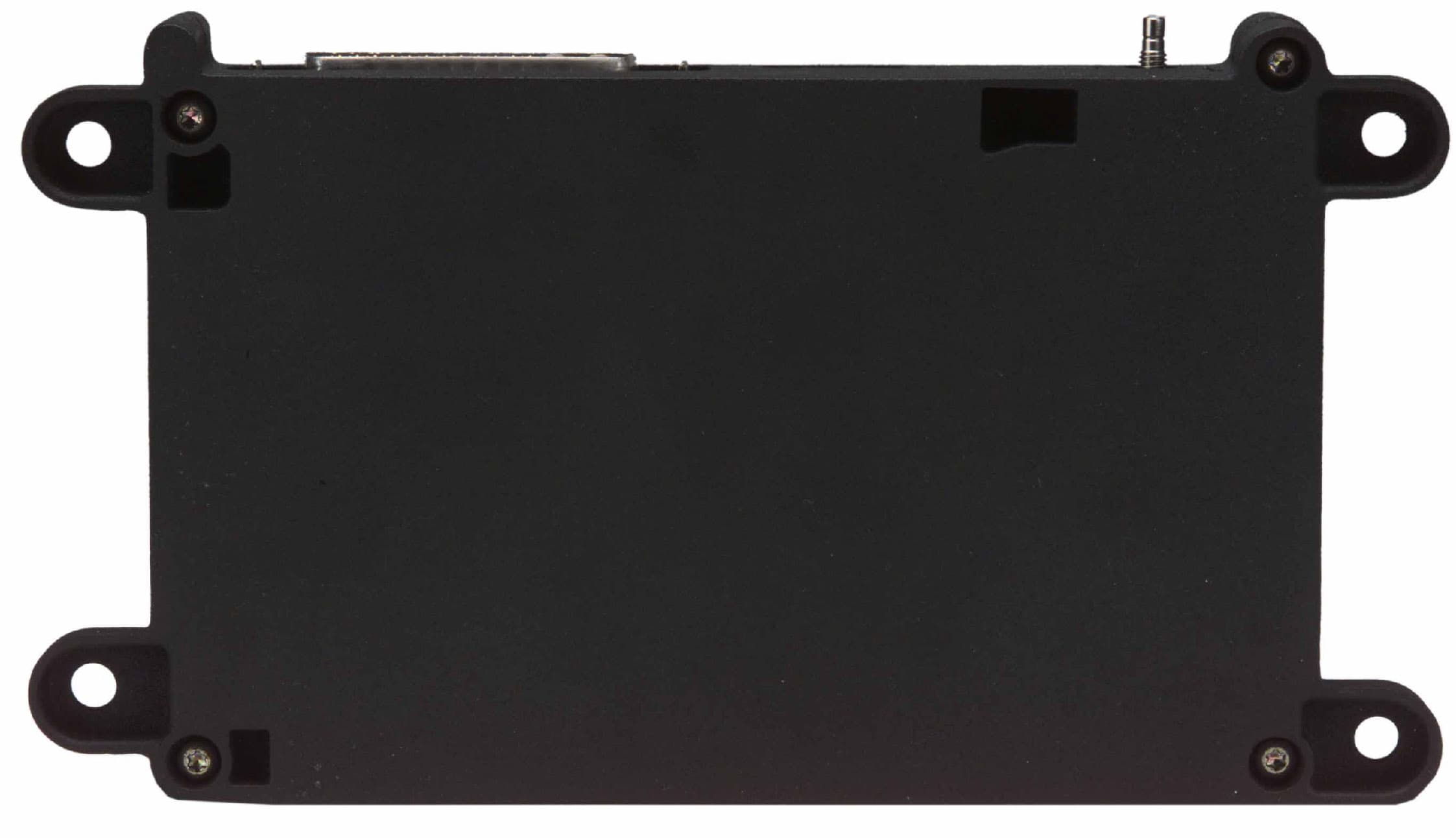
Click to zoom
Application Details
- Equipment Class
- TNB - Licensed Non-Broadcast Station Transmitter
- Date of Grant
- Feb 06, 2000
- Application Purpose
- Original Equipment
- Date of Application
- Oct 07, 1999
- Equipment Note
- Mobile Cellular Transceiver
- Frequency Range
- 824.00000000 - 849.00000000
- Company
- Motorola Mobility LLC
- Country
- United States
Documents & Files
Document Text
Text extracted from the exhibit documents filed with the FCC. Open a document above to read the original.
Users Manual
APPLICANT: MOTOROLAFCC ID: IHDT5ZY1 EXHIBIT 8 USER MANUAL INFORMATION This product provides automatic notification of emergency and status information. Only minimal user interface is possible. Limited user documentation may be provided by individual automobile manufacturers. If requested by the FCC, Motorola will contact the automobile manufacturers to obtain their specific wording or actual manuals. IMPORTANT INSTALLATION INFORMATION Motorola provides the following information, with the product, when delivered to the automobile manufacturer: ANTENNA INSTALLATION IMPORTANT: To meet the FCC’s RF Exposure Guidelines, the antenna should be installed so there is at least 30 cm of separation between the body of the user and nearby persons and the antenna.
Users Manual
APPLICANT: MOTOROLAFCC ID: IHDT5ZY1 EXHIBIT 8 Revised 1-21-00 USER MANUAL INFORMATION This product provides automatic notification of emergency and status information. Only minimal user interface is possible. Limited user documentation may be provided by individual automobile manufacturers. If requested by the FCC, Motorola will contact the automobile manufacturers to obtain their specific wording or actual manuals. IMPORTANT INSTALLATION INFORMATION Motorola provides the following information, with the product, when delivered to the automobile manufacturer: (Draft copy follows:) ANTENNA INSTALLATION IMPORTANT: To meet the FCC's RF Exposure Guidelines, the antenna should be installed to ensure a minimum distance between the body of the user and nearby persons and the antenna. To determine the minimum distance, calculate the combined cable loss and antenna gain and refer to the graph below to identify the required minimum separation distance in centimeters. Combined Cable Loss and Antenna Gain vs. Minimum Separation Distance -4 -3 -2 -1 0 1 2 3 4 5 20253035404550 Minimum Separation Distance (cm) Combined Cable Loss and Antena Gain (dB)
Attestation Statements
APPLICANT: MOTOROLA, INC. FCC ID: IHDT5ZY1 EXHIBIT 2A STATEMENT OF CERTIFICATION The technical data supplied with this application, having been taken under my supervision is hereby duly certified. The following is a statement of my qualifications: Engineering Diploma (MSEE) 1982 Polytechnic Institute of Timisoara, Romania 9 years experience in Computer equipment design 2 years experience in Cellular radiotelephone design SIGNATURE: NAME: Valeriu Boncu DATE: September 30, 1999 POSITION: Electrical Engineer I hereby certify that the above application was prepared under my direction and that to the best of my knowledge and belief, the facts set forth in the application and accompanying technical data are true and correct. SIGNATURE: NAME: Nick Grivas DATE: September 30, 1999 POSITION: Engineering Section Manager APPLICANT: MOTOROLA, INC.FCC ID: IHDT5ZY1 EXHIBIT 2B September 30, 1999 Engineer-in Charge Equipment Authorization Branch Federal Communications Commission We hereby certify that this transmit and receive equipment (FCC ID: IHDT5ZY1) for mobile station cellular system use is in full compliance with all parts of Section 2 of TIA/EIA-IS-88 "Mobile Station-Land Station Compatibility Standard for Dual Mode Narrowband Analog Cellular Technology," dated January 1993, which incorporates EIA/TIA-553 "Mobile Station-Land Station Compatibility Specification" and with OET Bulletin No. 53 "Cellular System Mobile Station-Land Station Compatibility Specification." SIGNATURE: NAME: Valeriu Boncu POSITION: Electrical Engineer Telematics Network Access Devices SIGNATURE: NAME: Nick Grivas POSITION: Engineering Section Manager Telematics Network Access Devices
Cover Letter(s)
APPLICANT: MOTOROLAFCC ID: IHDT5ZY1 Exhibit 13 October 15, 1999 CONFIDENTIALITY REQUEST CONTAINED WITHIN Federal Communications Commission Authorization and Evaluation Division 7435 Oakland Mills Road Columbia, Maryland 21046 Re: Application for Cellular Transceiver Type Acceptance Gentlemen: Application: Motorola, Inc., Personal Communications Sector, 600 N. U.S. Highway 45, Libertyville, Illinois 60048-1286 herein submits: Application for Equipment Authorization (FCC Form 731-October 1992 with integrated Fee Processing Form, Fee Codes EFT and EBC), application fee in the amount of $610, and Exhibits; for Type Acceptance of a Cellular Transceiver, FCC ID: IHDT5ZY1. Motorola is also the manufacturer of this equipment. Confidentiality: Pursuant to Section 0.459 of the Commission's rules (CFR 47), Motorola requests confidentiality for portions of the material contained in this application and that the identified material be withheld from public inspection following the grant of this authorization. This material contains Motorola's trade secrets and confidential information that Motorola does not customarily release to the public and which is otherwise not generally available to the public. Confidentiality is requested for the following exhibits: • Exhibit 4 Block Diagrams • Exhibit 5 Schematics • Exhibit 12 Operational Description Description: This equipment is a mobile device with the capability to operate in the conventional Analog Cellular standard in the 800 MHz cellular band. Technical details for this cellular technology are detailed in Exhibit 12. Contact Information: Please contact me by telephone at (847) 523-6167, by facsimile at (847) 523-2350, or by e-mail ([email protected]), if there are any further questions or additional information needed concerning this filing. Regards, Andrew J. Bachler FCC Liaison Cellular Subscriber Sector 600 N. U.S. Highway 45 Libertyville, IL 60048-5343
Cover Letter(s)
APPLICANT: MOTOROLA FCC ID: IHDT5ZY1 Exhibit 13a October 22, 1999 CORRECTION TO FORM 731 Federal Communications CommissionAuthorization and Evaluation Division7435 Oakland Mills RoadColumbia, Maryland 21046Re: Correction to Form 731Details: Please delete the third line entry in item 12. This equipment does not have NAMPS capability. The entry was made in error. Contact Information: Please contact me by telephone at (847) 523-6167, by facsimile at (847) 523-2350, or by e-mail ( [email protected]) , if there are any further questions or additional information needed concerning this filing.Regards,Andrew J. BachlerFCC LiaisonCellular Subscriber Sector600 N. U.S. Highway 45Libertyville, IL 60048-5343
External Photos
Exhibit 3-1 Top View Side View FCC ID LABEL LOCATION FCC ID LABEL LOCATION APPLICANT: MOTOROLA, INC. TRANSCEIVER TYPE: IHDT5ZY1 APPLICANT: MOTOROLA, INC. TRANSCEIVERTYPE: IHDT5ZY1 Bottom View Connector Side View Exhibit 3-2 FCC ID Label Loacation
ID Label/Location Info
APPLICANT: MOTOROLA, INC.FCC ID: IHDT5ZY1 EXHIBIT 1 FCC IDENTIFICATION (NAMEPLATE) INFORMATION The FCC label shown is the label that will appear on the radio when in production. It will be placed on the outside of the radiotelephone. (Refer to exhibit 3). MOTOROLA INC. FCC ID: IHDT5ZY1
Internal Photos
Exhibit 9 APPLICANT: MOTOROLA, INC. TRANSCEIVER TYPE: IHDT5ZY1 Transceiver Board Side 1 (Shields Removed) Side 2 (Shields Removed)
Parts List/Tune Up Info
APPLICANT: MOTOROLA, INC.FCC ID: IHDT5ZY1 EXHIBIT 10 TRANSCEIVER ADJUSTMENTS/TUNE-UP PROCEDURE There are no user accessible adjustments or tuning in this mobile cellular transceiver. All necessary adjustments and tuning are performed during manufacture of the product. Any adjustments or tuning after service or repair are done as part of that process as special equipment is required to perform such adjustments.
RF Exposure Info
1 1 October 7, 1999 SAR Test Report for Motorola 800 MHz mobile cellular phone (FCC ID IHDT5ZY1). Prepared by: Paul Moller, Principal Staff Engineer Motorola Personal Communications Sector Product Safety Laboratory Libertyville, Illinois The Motorola Personal Communications Sector Product Safety Laboratory has evaluated the 800 MHz mobile cellular phone, FCC ID IHDT5ZY1, for the need to conduct SAR evaluation. Due to the design and installation of this product, it is not possible to conduct SAR evaluation. This is because Motorola neither manufactures or supplies the antenna(s) that will be used in the installation of this product. Therefore, this product will be evaluated as a mobile device per 47 CFR §1.1310 titled “Radiofrequency radiation exposure limits”, generally referred to as MPE limits. In 47 CFR § 2.1091, paragraph (b) defines a mobile device as “a transmitting device designed to be used in other than fixed locations and to generally be used in such a way that a separation distance of at least 20 centimeters is normally maintained between the transmitter’s radiating structure(s) and the body of the user or nearby persons.” The 800 MHz mobile cellular phone is intended to be installed into a vehicle such that the unit is physically secured at one location. In the installation guide supplied with the product, Motorola has the following statement: “IMPORTANT: To meet the FCC’s RF Exposure Guidelines, the antenna should be installed so there is at least 30 cm of separation between the body of the user and nearby persons and the antenna”. Based on the installation of the transceiver and the antenna, the transmitter's radiating structure is more than 20 centimeters from the user. Thus, the 800 MHz mobile cellular phone is a “mobile device” as defined in section § 2.1091 paragraph (b). Table 1 (B) of 47 CFR §1.1310 lists the limits for MPE for the General Population. Since the mobile cellular phone operates in the 800 MHz cellular band, the listed limit of f/1500 applies. The lowest transmit frequency for this product is 824.04 MHz, resulting in a lowest maximum MPE of 0.55 mW/cm 2 . Since Motorola neither manufactures or supplies the antenna(s) that will be used in the installation of this product, it is not possible to measure the MPE of the actual phone and antenna as it is installed per the installation manual. Therefore a calculation of MPE will be described in the next paragraph. The MPE of an antenna can be calculated by knowing the transmit EIRP and the distance at which MPE is being calculated. The model used for calculating power density in OET Bulletin 65, Edition 97-01, is the spherical model. In this case power density will be calculated at 30 cm, which is the minimum separation between the body of the user and nearby persons and the antenna per the installation manual. The maximum transmit power for the 800 MHz mobile cellular phone is 3.8 Watts. When installed using a combined cable loss and antenna gain of a maximum of 1.2 dBi, the maximum EIRP is 5.0 Watts. Using the spherical model, power density is found to be 0.44 mW/cm2 at a distance of 30cm from the antenna. Therefore, by requiring the user and nearby persons to remain at least 30cm from the antenna, the MPE is not exceeded. 2 2 A picture of the 800 MHz mobile cellular phone is shown in figure 1 below. Figure 1, Side View.
RF Exposure Info
APPLICANT: MOTOROLAFCC ID: IHDT5ZY1 Exhibit 13A January 21, 2000 RESPONSE TO SAR QUESTIONS (Correspondence Reference Number: 11299) Federal Communications Commission Authorization and Evaluation Division 7435 Oakland Mills Road Columbia, Maryland 21046 Re: Application for Cellular/PCS Transceiver Certification (EA95622) Kwok Chan & Frank Coperich: Purpose: This document responds to Correspondence Reference Number 11299, SAR questions on the IHDT5ZY1 (EA95622) application. Description: To facilitate the response to SAR questions, the following includes the original text and the highlighted response. A draft copy of a revised User’s manual document is also included. Re:FCC ID IHDT5ZY1 Applicant:Motorola Inc Correspondence Reference Number:11299 731 Confirmation Number:EA95622 Date of Original E-Mail:01/04/2000 1. The filing is requesting 3.0 W conducted output, based on measurements. The RF exposure information exhibit is indicating a maximum output of 3.8 W. The discrepancy needs to be resolved. RESPONSE: The 3.8 W is the maximum that a transceiver can produce. The product is actually phased at 3.0 W. To ensure absolute worst case MPE evaluation, calculations assume 3.1 Watts conducted power. 2. "Transmitter Operation Description" section of exhibit 12, Technical Descriptions paragraph, indicates the entire transmitter is capable of 6.3 W of maximum output. Previous section, "Description", indicates the transmitter is designed to be used with a 3 dB gain roof (vehicle) mounted antenna with 3 W maximum output (less than 6 W EIRP). The RF exposure information exhibit is indicating a maximum EIRP of 5.0 W with 1.2 dB of combined antenna gain and cable loss (no specific antenna gain specified, but implying a minimum of 1.8 dB cable loss). Please clarify discrepancies. RESPONSE: The 6.3 Watt level refers to the maximum power that the transmit section (PA device) of the transceiver can produce. Losses between this point and the antenna port are 2.65 dB. This leaves about 0.5 dB headroom to ensure that the transceiver can be "phased" for 3.0 W at the antenna port. The antenna installation guidelines chart includes combination line loss and antenna gain which apply to all installations. 3. At higher than 1.5 W ERP (2.46 W EIRP), this transmitter is not categorically excluded from routine MPE evaluation for demonstrating compliance. The "Technical Description" section has already defined the design of this transmitter is for used with a 3 dB gain roof-mount antenna for vehicle operations. The normal operating APPLICANT: MOTOROLAFCC ID: IHDT5ZY1 Exhibit 13A conditions for evaluating RF exposure with respect to MPE limits, in this case, would be the intended 3 dBi antenna(s) over a metal ground plane. The following alternatives may be considered - (a) Applicant demonstrates MPE compliance with respect to the type(s) of antennas intended for this transmitter for supporting worst case exposure conditions. Depending on the final information supplied and whether it is to be installed by vehicle manufacturers and its dealers with clearly defined installation requirements, we may need to include the minimum cable loss, maximum antenna gain, antenna types and lengths (or ones tested) on the grant for purposes of satisfying MPE requirements. Antennas with substantially equivalent performance and physical constructions will be allowed. (b) The applicant specifically requests for an exclusion from routine MPE evaluation with supporting reasons - usually due to transmitter configuration(s) that cannot be properly tested because of technical reasons and difficulties or other factors that will result in RF exposure conditions substantially lower than the applicable limits. In such cases, worst case estimates may be considered according to maximum output power, feasibility of the intended installation and operating requirements for satisfying MPE compliance, maximum antenna gain, antenna type, antenna length that may affect exposure conditions and associated cable losses etc. These similar requirements will be considered as grant conditions for satisfying compliance. (c) The provided manual information indicates this transmitter is intended for installation by automobile manufacturers. If the intended type(s) of antennas are known, it would be easier to perform MPE for demonstrating compliance, which will most likely result in less restrictive grant conditions. If there is supporting information to demonstrate it can qualify for an exclusion from routine MPE evaluation due to technical reasons, more restrictive installation and operating conditions are likely for the grant. If the exposure conditions cannot be clearly defined, it may be necessary to require the grantee to coordinate and ensure MPE compliance with automobile manufacturers. RESPONSE: Motorola reviewed all eleven vehicle installation scenarios currently planned by the OEM automobile manufacturer. In these installations, line loss varied from 6.8 to 9.1 dB. Antennas are typically unity gain (1.5 dB) ¼ wave ground planes, combination antennas, or low gain patch antennas. To accommodate the FCC RF exposure guidelines, for all of these installations and future installation scenarios, Motorola provides an antenna installation guideline chart. This chart provides the recommended distance between all nearby persons and the antenna, for various antenna gain and line loss situations. Please refer to the draft copy of the user (installer) manual. Contact Information: Thank you for this special consideration. Please contact me by telephone at (847) 523-6167, by facsimile at (847) 523-2350, or by e-mail ([email protected]), if there are questions or additional information needed concerning this filing. Regards, Andrew J. Bachler FCC Liaison Cellular Subscriber Sector 600 N. U.S. Highway 45 Libertyville, IL 60048-5343
RF Exposure Info
APPLICANT: MOTOROLAFCC ID: IHDT5ZY1 Exhibit 13B February 3, 2000 RESPONSE TO SAR QUESTIONS (Reference 2/2/00 Frank Coperich e-mail Federal Communications Commission Authorization and Evaluation Division 7435 Oakland Mills Road Columbia, Maryland 21046 Re: Application for Cellular/PCS Transceiver Certification (EA95622) Kwok Chan & Frank Coperich: Purpose: This document responds to a 2/2/00 e-mail from Kwok Chan to Frank Coperich. The e-mail addressed additional rf exposure issues on EA95622, the IHDT5ZY1 application. Previous rf exposure issues were enclosed in Correspondence Reference Number 11299. Description: To facilitate the response to SAR questions, the following includes the original text and the highlighted response. Frank: Motorola, EA 95622 - 1. Reply received on 1/24/00 has a zero byte file uploaded to exhibit 6 - conducted and spurious etc. RESPONSE: This file was resent on 2/2/00. It was submitted into the Exhibit 6, test report folder. I can provide confirmation details if George Tannahill requests them. 2.RF exposure responses indicated the antenna installation for this device has line losses of 6.8-9.1 dB, typically using 1.5 dBi gain antennas. The device has 3.1 W (34.9 dBm) maximum conducted output (requesting 3.0 W). Since no MPE data has been submitted, operations for this transmitter must satisfy the 1.5 W ERP (2.46 W EIRP) categorical exclusion requirements of 2.1091. This implies cable loss and antenna gain must not exceed -1.0 dB (34.9 dBm-1.0 dB = 33.9 dBm = 2.46 W EIRP). The proposed minimum separation distance plot for antenna installation includes data for much higher output which do not apply to this transmitter and could cause confusion to the installer. Please revise the proposed antenna installation statement accordingly; suggestion - IMPORTANT: Antennas for this transmitter should be mounted externally on a vehicle, with the minimum separation distance indicated in the graph below from users and nearby persons, to comply with FCC RF exposure limits and satisfying categorical exclusion requirements for mobile transmitters. The combined cable loss and antenna gain must not exceeding -1.0 dB to maintain a total system output of 1.5 W ERP (2.46 W or 33.9 dBm EIRP) to satisfy RF exposure requirements for this transmitter. RESPONSE: Motorola agrees that the least confusing approach is to evaluate the rf exposure and provide clear and concise instructions to the installer to maintain the categorical exclusion requirements of 2.1091. The following information is incorporated into the Installers Guide: APPLICANT: MOTOROLAFCC ID: IHDT5ZY1 Exhibit 13B IMPORTANT To comply with the FCC RF exposure limits and satisfy the categorical exclusion requirements for mobile transmitters, all of the following requirements must be met: 1. The transmit antenna is mounted externally on the vehicle. 2. A minimum separation distance of 20 cm is maintained between the antenna and the users and nearby persons. 3. The transmitter conducted power (3.1 Watts or 34.9 dBm) is reduced to a maximum of 1.5 Watts ERP (2.46 Watts or 33.9 dBm EIRP). This requires the combination of antenna gain and feed line loss to attenuate the transmit signal by a minimum of 1.0 dB. 3. Please confirm that this is not a user installed transmitter. Response #3 indicted "user (installer)" and elsewhere indicated it is intended for OEM automobile manufacturers. If it is user installable, detail installation instructions and requirements should be provide for the typical non-skilled users to satisfy RF exposure requirements. RESPONSE: Confirmed, this equipment is installed by a trained OEM technician. Note: Output is 3.0 W at the antenna terminal of the device. Proposed Grant Conditions: This OEM transmitter operates with external vehicle-mounted antennas. The antenna installation must provide the minimum separation distance, determined in this filing, from users and nearby persons to satisfy RF exposure requirements. The combined cable loss and antenna gain must not exceed -1.0 dB and total system output must not exceed 1.5 W ERP (2.46 W EIRP) to qualify for categorical exclusion requirements of 2.1091. OEM installers must be given appropriate installation requirements to satisfy RF exposure compliance. Contact Information: Thank you for this special consideration. Please contact me by telephone at (847) 523-6167, by facsimile at (847) 523-2350, or by e-mail ([email protected]), if there are questions or additional information needed concerning this filing. Regards, Andrew J. Bachler FCC Liaison Cellular Subscriber Sector 600 N. U.S. Highway 45 Libertyville, IL 60048-5343
Test Report
APPLICANT: MOTOROLA, INC.FCC ID: IHDT5ZY1 EXHIBIT 6 SUBMITTED MEASURED DATA INDEX 6ARF Power Output - Measured Data 6BAudio Response - Graph 6CPost Limiter Low Pass Filter Response - Graph 6DSignaling Channel Audio Roll-Off Filter Response - Graph 6E-1Modulation Limiting (Compandor On) - Graph 6E-2Modulation Limiting (Compandor Off) - Graph 6F-1Occupied Bandwidth, Audio - Photograph 6F-2Occupied Bandwidth, Audio and SAT - Graph 6F-3Occupied Bandwidth, Wideband Data - Graph 6F-4Occupied Bandwidth, Signaling Tone and SAT - Graph 6GConducted Spurious and Harmonic Emissions, -Graph 6HRadiated Spurious and Harmonic Emissions, -Graph 6JReference Oscillator Stability vs. Temperature - Graph 6KReference Oscillator Stability vs. Supply Voltage APPLICANT: MOTOROLA, INC.FCC ID: IHDT5ZY1 EXHIBIT 6A RF POWER OUTPUT DATA The input supply to the transmitter was set at 13.7 Volts. The RF power output was measured with the indicated voltage and current applied into the final RF amplifying device(s). Measured RF output: 3 W Measured DC voltage: 13.7 V Measured DC current: 450 mA Measured RF input: 0.4 W APPLICANT: MOTOROLA, INC. FCC ID: IHDT5ZY1 EXHIBIT 6B A UDIO RESPONSE -40-30-20-10 0 1020 100 1000 10000 Frequency (Hz) Modulation (dB) Upper LimitLower LimitModulation Log Page: 569157Date: 9/1/1999Signature: ______________ APPLICANT: MOTOROLA, INC. FCC ID: IHDT5ZY1 EXHIBIT 6C Post-Limiter Low Pass Filter Response -60-55-50-45-40-35-30-25-20-15-10 -5 05 10 100 1000 10000 100000 Frequency (Hz) Amplitude (dB) Post Limiter Filter ResponseSpecification REFERENCE: 1kHz = 0 dBMETHOD: Constant InputLOG PAGE: N/ADATE: 9/1/1999SIGNATURE:________________ 40*log(f/3000) dB APPLICANT: MOTOROLA, INC. FCC ID: IHDT5ZY1 EXHIBIT 6D Signaling Channel Audio Roll-Off Filter Response -60-55-50-45-40-35-30-25-20-15-10 -5 05 10 100 1000 10000 100000 Frequency (Hz) Amplitude (dB) Filter ResponseFilter Limit 80*log(f/20000) REFERENCE: 1kHz = 0 dBMETHOD: Constant InputLOG PAGE: N/ADATE: 9/1/1999SIGNATURE:________________ APPLICANT: MOTOROLA, INC. FCC ID: IHDT5ZY1 EXHIBIT 6E-1 Modulation Limiting (Compandor On) 0123456789 1011121314 -60 -50 -40 -30 -20 -10 0 10 20 Audio Level (dB) Deviation (kHz) 300 Hz1000 Hz3000 Hz APPLICANT: MOTOROLA, INC. FCC ID: IHDT5ZY1 EXHIBIT 6E-2 Modulation Limiting (Compandor Off) 0123456789 101112 -60 -50 -40 -30 -20 -10 0 10 20 Audio Level (dB) Deviation (kHz) 300 Hz1000 Hz3000 Hz APPLICANT: MOTOROLA, INC.FCC ID: IHDT5ZY1 EXHIBIT 6F-1 BANDWIDTH MEASUREMENT DATA FOR TRANSMITTER TYPES F8W DEVIATION OF THE CARRIER WITH 2500 Hz AUDIO MODULATION HORIZONTAL SCALE = 20 kHz/DIVISION VERTICAL SCALE = 10 dB/DIVISION (ATTENUATION) RESOLUTION BANDWIDTH = 300 Hz AUDIO LEVEL = 16 dB GREATER THAN LEVEL REQUIRED TO PRODUCE ±6kHz PEAK FM DEVIATION POWER LEVEL = 3 W MEASURED DATA: 1. Instantaneous Deviation Control set for a maximum of ±12 kHz. 2. Tune and adjust to obtain unmodulated carrier on the analyzer scope. Save trace of unmodulated carrier. APPLICANT: MOTOROLA, INC.FCC ID: IHDT5ZY1 EXHIBIT 6F-1 3. Modulate the transmitter with a 2.5 kHz tone, 16 dB greater than that required to produce ±6 kHz deviation. Photograph the sideband display while it is superimposed upon the unmodulated carrier. SPEC LIMITS: a. On any frequency removed from the assigned carrier frequency by more than 20 kHz, up to and including 45 kHz, the sideband is at least 26 dB below the carrier. b. On any frequency removed from the assigned carrier frequency by more than 45 kHz, the sideband is at least 63 + 10log 10 (mean power output in Watts) dB below the carrier. APPLICANT: MOTOROLA, INC.FCC ID: IHDT5ZY1 EXHIBIT 6F-2 BANDWIDTH MEASUREMENT DATA FOR TRANSMITTER TYPES F8W DEVIATION OF THE CARRIER WITH 2500 Hz AUDIO MODULATION AND SUPERVISORY AUDIO TONE HORIZONTAL SCALE = 20 kHz/DIVISION VERTICAL SCALE = 10 dB/DIVISION (ATTENUATION) RESOLUTION BANDWIDTH = 300 Hz AUDIO LEVEL = 16 dB GREATER THAN LEVEL REQUIRED TO PRODUCE ±6kHz FM DEVIATION POWER LEVEL = 3 W MEASURED DATA: APPLICANT: MOTOROLA, INC.FCC ID: IHDT5ZY1 EXHIBIT 6F-2 1. Instantaneous Deviation Control set for a maximum of ±12 kHz. 2. Tune and adjust to obtain unmodulated carrier on the analyzer scope. Save trace of unmodulated carrier. 3. Modulate the transmitter with a 2.5 kHz tone, 16 dB greater than that required to produce ±6 kHz deviation and add a 6 kHz SAT with ±2 kHz deviation. Photograph the sideband display while it is superimposed upon the unmodulated carrier. SPEC LIMITS: a. On any frequency removed from the assigned carrier frequency by more than 20 kHz, up to and including 45 kHz, the sideband is at least 26 dB below the carrier. b. On any frequency removed from the assigned carrier frequency by more than 45 kHz, the sideband is at least 63 + 10log 10 (mean power output in Watts) dB below the carrier. APPLICANT: MOTOROLA, INC.FCC ID: IHDT5ZY1 EXHIBIT 6F-3 BANDWIDTH MEASUREMENT DATA FOR TRANSMITTER TYPES F1D DEVIATION OF THE CARRIER WITH WIDE BAND DATA HORIZONTAL SCALE = 20 kHz/DIVISION VERTICAL SCALE = 10 dB/DIVISION (ATTENUATION) RESOLUTION BANDWIDTH = 300 Hz POWER LEVEL = 3 W MEASURED DATA: 1. Instantaneous Deviation Control set for a maximum of ±12 kHz. 2. Tune and adjust to obtain unmodulated carrier on the analyzer scope. Save trace of unmodulated carrier. APPLICANT: MOTOROLA, INC.FCC ID: IHDT5ZY1 EXHIBIT 6F-3 3. Modulate the transmitter with quasi-random 10 kilobit/second wide band data with ±8 kHz peak deviation. Photograph the sideband display while it is superimposed upon the unmodulated carrier. SPEC LIMITS: a. On any frequency removed from the assigned carrier frequency by more than 20 kHz, up to and including 45 kHz, the sideband is at least 26 dB below the carrier. b. On any frequency removed from the assigned carrier frequency by more than 45 kHz, up to and including 60 kHz, the sideband is at least 45 dB below the carrier. c. On any frequency removed from the assigned carrier frequency by more than 60 kHz, up to and including 90 kHz, the sideband is at least 6…
Text truncated - open the document above for the full version.
Test Report
APPLICANT: MOTOROLA, INC. FCC ID: IHDT5ZY1 EXHIBIT 6G Revised 1/42/00 TRANSMITTER CONDUCTED SPURIOUS AND HARMONIC EMISSIONS Carrier Power: 3W to 4.8mW in 4dB steps. Carrier Frequency: 824.04 to 848.97 MHz in 30kHz steps. Each reported emission reflects the highest absolute level found among all power levels and channels All emissions not reported were greater than 25 dB below the FCC specification. No signals greater than –80dBm were found in the 869 to 894 MHz band. Spectrum was searched from 1MHz to the 10 th harmonic of the transmitter. SPURIOUS LEVEL (dBc) HARMONIC OF CARRIERFREQUENCY FROM CARRIER (MHz) -70.8 -60.8 -40.8 -20.8 0 -30 -10 10 34.8 SPURIOUS LEVEL (dBm) -10 0+10765432-5+5 Carrier @ 34.8 dBm Specification Limit: 34.8-(43+10log(carrier power)) = -13.00 dBm 1089 Data Taken at L.S. Compliance, Inc. Measurement Facility ID Number: 31040/SIT 9-15-99 to 11-2-99 30 20 0 -20 -10.8 -30.8 -50.8 APPLICANT: MOTOROLA, INC. FCC ID: IHDT5ZY1 EXHIBIT 6H Revised 1/24/00 TRANSMITTER RADIATED SPURIOUS AND HARMONIC EMISSIONS Carrier Power: 3W to 4.8mW in 4dB steps. Carrier Frequency: 824.04 to 848.97 MHz in 30kHz steps. Each reported emission reflects the highest absolute level found among all power levels and channels. All emissions not reported were greater than 25 dB below the FCC specification. No signals greater than –80dBm were found in the 869 to 894 MHz band. Spectrum was searched from 30 MHz to the 10 th harmonic of the transmitter. SPURIOUS LEVEL (dBc) HARMONIC OF CARRIERFREQUENCY FROM CARRIER (MHz) -70.8 -60.8 -40.8 -20.8 0 -30 -10 10 34.8 SPURIOUS LEVEL (dBm) -10 0+10765432-5+5 Carrier @ 34.8 dBm Specification Limit: 34.8-(43+10log(carrier power)) = -13.00 dBm 1089 Data Taken at L.S. Compliance, Inc. Measurement Facility ID Number: 31040/SIT 9-15-99 to 12-29-99 30 20 0 -20 -10.8 -30.8 -50.8
Test Report
APPLICANT: MOTOROLA, INC. FCC ID: IHDT5ZY1 EXHIBIT 6G Revised 1/24/00 TRANSMITTER CONDUCTED SPURIOUS AND HARMONIC EMISSIONS Carrier Power: 3W to 4.8mW in 4dB steps. Carrier Frequency: 824.04 to 848.97 MHz in 30kHz steps. Each reported emission reflects the highest absolute level found among all power levels and channels All emissions not reported were greater than 25 dB below the FCC specification. No signals greater than –80dBm were found in the 869 to 894 MHz band. Spectrum was searched from 1MHz to the 10 th harmonic of the transmitter. SPURIOUS LEVEL (dBc) HARMONIC OF CARRIERFREQUENCY FROM CARRIER (MHz) -70.8 -60.8 -40.8 -20.8 0 -30 -10 10 34.8 SPURIOUS LEVEL (dBm) -10 0 +10 765432-5 +5 Carrier @ 34.8 dBm Specification Limit: 34.8-(43+10log(carrier power)) = -13.00 dBm 108 9 Data Taken at L.S. Compliance, Inc. Measurement Facility ID Number: 31040/SIT 9-15-99 to 11-2-99 30 20 0 -20 -10.8 -30.8 -50.8 APPLICANT: MOTOROLA, INC. FCC ID: IHDT5ZY1 EXHIBIT 6H Revised 1/24/00 TRANSMITTER RADIATED SPURIOUS…
Text truncated - open the document above for the full version.
Contact Information
Applicant
Jeff Narducci(Director Product Compliance)
Technical Specifications
| # | Rule Parts | Frequency Range | Power Output | Emission | Tolerance |
|---|---|---|---|---|---|
| 2 | 22H | 824 MHz - 849 MHz | 3 W | 40K0F8W | 0.00025 % |
Other Applications from Motorola Mobility LLC
IHDT56AW9
May 12, 2026Smart Watch
Equipment Class
NII - Unlicensed National Information Infrastructure TXIHDT56AW5
Apr 08, 2026Mobile Cellular Phone
Equipment Class
DTS - Digital Transmission SystemIHDT56AW6
Mar 18, 2026Smart Watch
Equipment Class
JBP - Part 15 Class B Computing Device PeripheralIHDT56AX4
Mar 17, 2026Mobile Cellular Phone
Equipment Class
PCE - PCS Licensed Transmitter held to earIHDT56AW3
Mar 03, 2026Mobile Cellular Phone
Equipment Class
6XD - 15E 6 GHz Low Power Indoor Client