IHDT6AC1
Motorola Mobility LLC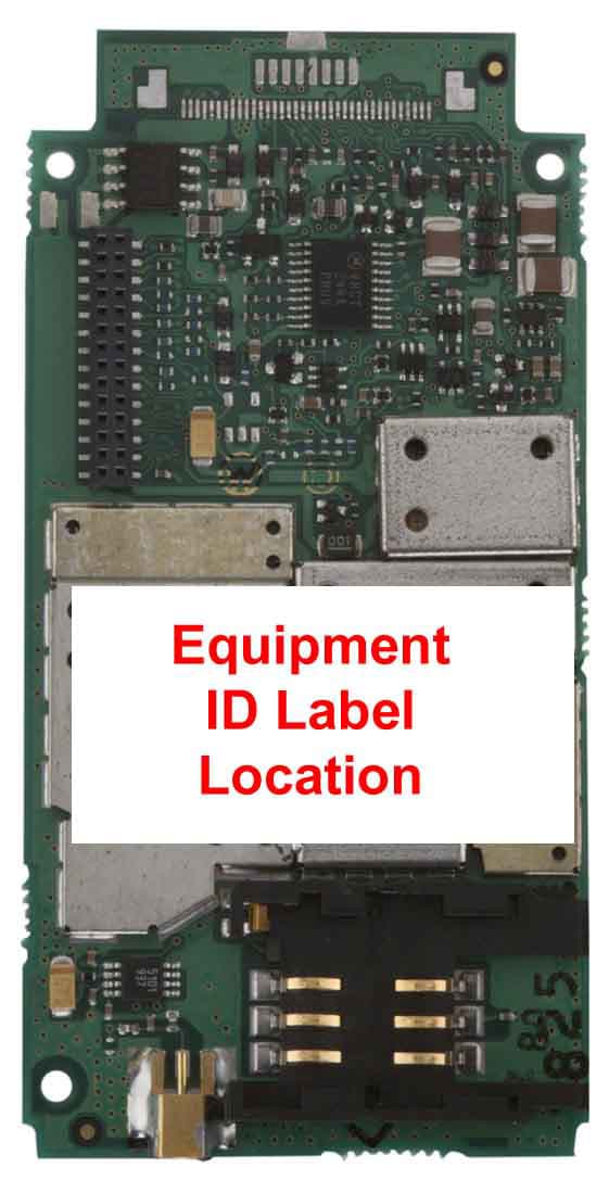
Click to zoom
Application Details
- Equipment Class
- TNB - Licensed Non-Broadcast Station Transmitter
- Date of Grant
- Jul 31, 2000
- Application Purpose
- Original Equipment
- Date of Application
- May 31, 2000
- Frequency Range
- 1850.20000000 - 1909.80000000
- Company
- Motorola Mobility LLC
- Country
- United States
Documents & Files
Document Text
Text extracted from the exhibit documents filed with the FCC. Open a document above to read the original.
Users Manual
APPLICANT: MOTOROLA, INC.FCC ID: IHDT6AC1 EXHIBIT 8 INSTRUCTION MANUAL A preliminary draft copy of the Users Manual follows. RF exposure information is located in section 1.3. APPLICANT: MOTOROLA, INC.FCC ID: IHDT6AC1 Exhibit 8 1 D15 – Developer Guide – 1 st draft 1. Introduction Product description The D15 model Main application SAR Requirements. 2. Installation Mechanical description Connections 3. Pin description & main Functionality Pin description of connectors per model Different communication & application 4. Modes of Operation On/Off process include time diagram Voice connection Full flow control data call Soft GSM Operation 5. Design Consideration Power supply Antenna Data level (VOH, VOL) Flex cable & external SIM Connector Environmental 6 Testing & service How to test a unit in a voice call How to test a unit in a data call How to test a unit in a soft GSM call How to test RF features Desense test 7. Appendix 1st. Specification 2nd. A list of AT command 3rd. Desense test APPLICANT: MOTOROLA, INC.FCC ID: IHDT6AC1 Exhibit 8 2 1. Introduction 1.1 Product Specification – See in Appendix bellow. To add a note thal all the Data/Audio/SIM signals are compatible with D10 User Device D10 30 pin FC D15 User Device 36 pin FC 3 lines removed from each side 1.2 D15 Models: • D15 DV (DV= Data & Voice) Standard. APPLICANT: MOTOROLA, INC.FCC ID: IHDT6AC1 Exhibit 8 3 • D15 DV Slim • D15 DVG Slim (DVG= Data, Voice, GPS) • D15 DV Board only (Vertical version & Horizontal version) APPLICANT: MOTOROLA, INC.FCC ID: IHDT6AC1 Exhibit 8 4 1.3 SAR Requirements User Operation Do not operate your telephone when a person is within 8 inches (20 centimeters) of the antenna. A person or object within 8 inches (20 centimeters) of the antenna could impair call quality and may cause the phone to operate at a higher power level than necessary and expose that person to RF energy in excess of that established by the FCC RF Exposure Guidelines. IMPORTANT The telephone must be installed in a manner that provides a minimum separation distance of 20 cm or more between the antenna and persons to satisfy FCC RF exposure requirements for mobile transmitting devices. Antenna Installation IMPORTANT: To comply with the FCC RF exposure limits and satisfy the categorical exclusion requirements for mobile transmitters, the following requirements must be met: 1. A minimum separation distance of 20 cm must be maintained between the antenna and all persons. 2. The transmitter effective radiated power must be less than 3.0 Watts ERP (4.9 Watts or 36.9 dBm EIRP). This requires that the combination of antenna gain and feed line loss does not exceed 16 dBi. APPLICANT: MOTOROLA, INC.FCC ID: IHDT6AC1 Exhibit 8 5 2. Installation – See details in PRD. Configuration 1 with d10 mounting Configuration 1 Configuration 1 with narrower mounting with narrower mounting APPLICANT: MOTOROLA, INC.FCC ID: IHDT6AC1 Exhibit 8 6 Configuration 1 with narrower mounting Configuration 2 Configuration 2 APPLICANT: MOTOROLA, INC.FCC ID: IHDT6AC1 Exhibit 8 7 Configuration 2 Configuration 2 APPLICANT: MOTOROLA, INC.FCC ID: IHDT6AC1 Exhibit 8 8 APPLICANT: MOTOROLA, INC.FCC ID: IHDT6AC1 Exhibit 8 9 3. Pin description & main Functionality 3.1 Standard model & Slim model The available functionality in these models are the follow: Data & Voice (D10 Replacement & Slim) - Connections D15 Main Process. Uart #1 RS232 port User logic Power supplies Main PWR Audio Data port EXT_SIM DSC General Data purposes DSC bus 3.1.1 Function available in the user connector – 36 pin ZIF • VCC input. 3.0 to 6Vdc • Full RS232 - 9 pins. TXD, RXD, RTS,CTS,DSR,DTR,DCD,RI at 5V levels. • External SIM connections.SIM Clock, SIM reset, SIM I/O, SIM VCC,SIM PD • DSC bus.DSC_EN, Downlink, Uplink – Motorola proprietary us. • Audio In/Out.Audio out and On/Off in the same pin, audio in Signal and analog ground. • Man_Test line.Used to detect standard Motorola accessories. • TS line (mobport).Used to turn on the radio. • TX_EN line.This line is an indication when the radio is transmitting. Note: 1. The Audio Out line is used to send out the detected audio and as a toggle On/Off pin. APPLICANT: MOTOROLA, INC.FCC ID: IHDT6AC1 Exhibit 8 10 2. The TS line is used to turn On the units by any transaction from Low to high in this pin. 3.1.2 Connector pin out Pin #FunctionPin #Function 1 TX_EN19SIM I/O 2 N.U.20SIM CLK 3 N.U.21TS 4 TXD22DSC_EN 5 RXD23Down Link 6 DTR24Up Link 7 DCD25Analog Ground 8 RTS26Ground 9 CTS27Ground 10 DSR28Ground 11RI29Ground 12 Manual_Test30VCC 13 Audio In31VCC 14 On/Off + Audio Out32VCC 15 N.U. 33VCC 16SIM _PD 34NU 17SIM _VCC 35NU 18SIM_Reset 36NU APPLICANT: MOTOROLA, INC.FCC ID: IHDT6AC1 Exhibit 8 11 3.2 D15 with GPS The available functionality in this models are the follow: Data & Voice + GPS model - Connections GPS (M12) D15 Main Process. GPS Process. Uart #1 RS232 port User logic Power supplies GPS Ant PWR 1PPS RX Diff Main PWR Audio Data port EXT_SIM DSC GPS purposes General Data purposes DSC bus Reg 3V 3.2.1 Function available in the user connector – 36 pin ZIF • VCC input. 3.0 to 6Vdc • Full RS232 - 9 pins. TXD, RXD, RTS,CTS,DSR,DTR,DCD,RI at 5V levels. • External SIM connections.SIM Clock, SIM reset, SIM I/O, SIM VCC,SIM PD • DSC bus.DSC_EN, Downlink, Uplink – Motorola proprietary us. • Audio In/Out.Audio out and On/Off in the same pin, audio in Signal and analog ground. • Man_Test line.Used to detect standard Motorola accessories. • TS line (mobport).Used to turn on the radio. • TX_EN line.This line is an indication when the radio is transmitting. • GPSTXD & RXD in 3V levels, 1PPS, APPLICANT: MOTOROLA, INC.FCC ID: IHDT6AC1 Exhibit 8 12 RTCM, Antenna power Note: 1. The Audio Out line is used to send out the detected audio and as a toggle On/Off pin. 2. The TS line is used to turn On the units by any transaction from Low to high in this pin. 3. The GPS is mounted on top of theD15 and receive power from the D15 but it is a stand-alone unit. The GPS is working from 3V and th…
Text truncated - open the document above for the full version.
Attestation Statements
APPLICANT MOTOROLA INC.FCC ID:IHDT6AC1 EXHIBIT 2A SPECIFICATION COMPLIANCE STATEMENT The transceiver type IHDT6AC1 has been tested in accordance with the requirements contained in the appropriate Commission regulations . To the best of my knowledge , these tests were performed using measurement procedures consistent with industry or Commission standards and demonstrate that this equipment complies with the appropriate standards . Each unit manufactured imported or marketed , will conform to the sample tested within the variations that can be expected due to quantity production and testing on a statistical basis . I further certify that the necessary measurements were made at Motorola , located at 3 Kremenetski street, Tel-Aviv, Israel, with the exception of Radiated Spurious Emissions testing which took place at L.S. Compliance, Inc., located at W66 N220 Commerce Court, Cedarburg, Wisconsin. NAME:Reuven Konevky TITLE:Section Manager TCG Development Signed: (Signed) Date : April 14, 2000 APPLICANT MOTOROLA INC.FCC ID:IHDT6AC1 EXHIBIT 2B STATEMENT OF CERTIFICATION The technical data supplied with this application , was taken under my supervision is hereby duly certified . I also certify that this transmit equipment (FCC ID : IHDT6AC1) compliance with all applicable parts of the FCC Rules . The following is a statement of my qualifications : NAME:Eitan Kugman TITLE:Senior Engineer TCG Development Signed: (Signed) Date : April 14, 2000 I hereby certify that the above application was prepared under my direction and that to the best of my knowledge and belief , the facts set forth in this application and accompanying technical data are true and correct . NAME:Eli Sasson TITLE:Lead Engineer TCG Development Signed: (Signed) Date : April 14, 2000
Cover Letter(s)
APPLICANT: MOTOROLAFCC ID: IHDT6AC1 Exhibit 13 June 1, 2000 CONFIDENTIALITY REQUEST CONTAINED WITHIN Federal Communications Commission Authorization and Evaluation Division 7435 Oakland Mills Road Columbia, Maryland 21046 Re: Application for PCS Transceiver Certification Gentlemen: Application: Motorola, Inc., Personal Communications Sector, 600 N. U.S. Highway 45, Libertyville, Illinois 60048-1286 herein submits: Application for Equipment Authorization (FCC Form 731-October 1992 with integrated Fee Processing Form, Fee Codes EFT and EBC), application fee in the amount of $610, and Exhibits; for Certification of a PCS Transceiver, FCC ID: IHDT6AC1. Motorola is also the manufacturer of this equipment. Confidentiality: Pursuant to Section 0.459 of the Commission's rules (CFR 47), Motorola requests confidentiality for portions of the material contained in this application and that the identified material be withheld from public inspection following the grant of this authorization. This material contains Motorola's trade secrets and confidential information that Motorola does not customarily release to the public and which is otherwise not generally available to the public. Confidentiality is requested for the following exhibits: • Exhibit 4 Block Diagrams • Exhibit 5 Schematics • Exhibit 12 Operational Description Description: This equipment is a GSM Embedded Module, which operates in the 1900 MHz PCS band. It can transfer data or voice over a GSM network. Model differences are dependent upon housing and external connector variations. Contact Information: Please contact me by telephone at (847) 523-6167 or by e-mail ([email protected]), if there are questions or additional information needed concerning this filing. Regards, Andrew J. Bachler FCC Liaison Personal Communications Sector 600 N. U.S. Highway 45 Libertyville, IL 60048-5343
External Photos
APPLICANT: MOTOROLA, INC. FCC ID: IHDT6AC1 EXHIBIT 3A Typical Non-Housed Unit (Bottom View) Typical Non-Housed Unit (Top View Showing ID Label on Shields) APPLICANT: MOTOROLA, INC. FCC ID: IHDT6AC1 EXHIBIT 3B Typical Housed Unit (Bottom View) Typical Housed Unit (Top View Showing ID Label )
ID Label/Location Info
APPLICANT: MOTOROLA INC.FCC ID: IHDT6AC1 EXHIBIT 1 FCC IDENTIFICATION (NAMEPLATE) INFORMATION The FCC label shown is representative of the label that will appear on the radio when in production. It will be placed on the outside of the equipment as shown in Exhibit 3. Other information may also be included on this label. FCC ID: IHDT6AC1
Internal Photos
APPLICANT: MOTOROLA, INC. FCC ID: IHDT6AC1 EXHIBIT 9 Typical Unit (Bottom View Shields Removed) Typical Unit (Top View Shields Removed) Note: External connector type varies depending upon model
Parts List/Tune Up Info
APPLICANT: MOTOROLA, INC.FCC ID: IHDT6AC1 EXHIBIT 10 TRANSCEIVER ADJUSTMENTS/TUNE-UP PROCEDURE There are no user accessible adjustments or tuning in this portable cellular transceiver. All necessary adjustments and tuning are performed during manufacture of the product. Any adjustments or tuning after service or repair are done as part of that process as special equipment is required to perform such adjustments.
RF Exposure Info
May 30, 2000 SAR Test Report for Motorola Mobile Phone FCC ID IHDT6AC1. Prepared by: Paul Moller, Principal Staff Engineer Motorola Personal Communications Sector Product Safety Laboratory Libertyville, Illinois The Motorola Personal Communications Sector Product Safety & Compliance Laboratory has evaluated the Mobile Phone FCC ID IHDT6AC1 for the need to conduct SAR evaluation. The appropriate standards are Federal Communications Commission section 47 CFR § 2.1091, the ANSI/IEEE C95.1 1992 and the NCRP Report Number 86. All of these standards have the same exclusionary requirements. Due to the design and installation of this product, it qualifies for the exclusion called out in Federal Communications Commission section 47 CFR § 2.1091 titled “Radiofrequency radiation exposure evaluation: mobile devices.” Based on the installation of the transceiver and the antenna, the transmitters radiating structure is more than 20 centimeters from the user. Thus, the Mobile Phone FCC ID IHDT6AC1 is a “mobile device” as defined in section § 2.1091 paragraph (b). Since the transceiver’s transmit frequency is above 1.5GHz and its ERP with the specified antenna is below 3 Watts, the Mobile Phone FCC ID IHDT6AC1 is “categorically excluded from routine environmental evaluation” per paragraph (c), and thus SAR evaluation is not required. Thus, the Mobile Phone FCC ID IHDT6AC1 does not require SAR evaluation.
RF Exposure Info
APPLICANT: MOTOROLAFCC ID: IHDT6AC1 Exhibit 13A July 28, 2000 RESPONSE TO SAR QUESTIONS (Correspondence Reference Number:15300) Federal Communications Commission Authorization and Evaluation Division 7435 Oakland Mills Road Columbia, Maryland 21046 Re: Application for Cellular/PCS Transceiver Certification (EA97767) Kwok Chan & Joe Dichoso: Purpose: This document responds to questions on the submission for the IHDT6AC1 (EA97767) application. Description: As requested , this response is placed in the rf exposure folder. Please place your reply in the RF exposure info folder. Indicate all antennas and their gains. Response: Motorola intends to market this rf device as an OEM product. Consequently, specific antenna and feedline selections are not included, but instead are chosen by the OEM to best suit the application. Section 1.3 in the users manual (exhibit 8) provides the necessary text to comply with the FCC RF exposure limits and satisfy the categorical exclusion requirements for mobile transmitters. Contact Information: Thank you for this special consideration. Please contact me by telephone at (847) 523-6167, or by e-mail ([email protected]), if there are questions or additional information needed concerning this filing. Regards, Andrew J. Bachler FCC Liaison Cellular Subscriber Sector 600 N. U.S. Highway 45 Libertyville, IL 60048-5343
Test Report
APPLICANT MOTOROLA INC. FCC ID:IHDT6AC1 Exhibit 6 1 TEST REPORT Exhibit Summary: EXHIBIT6 contains worst case measurement data that was taken on five different D15 Module configuration, listed below: 1. D15 DV (DV= Data & Voice) Standard 2. D15 DV Slim 3. D15 DVG Slim (DVG= Data, Voice, GPS) 4. D15 DV Board only (Vertical version) 5. D15 DV Board only (Horizontal version) Contents: RF Power Output.....................................................6A Final Amplifier Voltages and Currents......................6B Radiated Spurious Emission...................................6C Occupied Bandwidth...............................................6D Conducted Spurious Emissions...............................6E Frequency Stability..................................................6F APPLICANT MOTOROLA INC. FCC ID:IHDT6AC1 Exhibit 6A 2 RF Output Power Exhibit Summary: EXHIBIT 6A contains both average and peak output powers for the mobile station. The peak power results are presented in tabular form which illustrates the deviation in power with respect to the average value. In all cases, the peak output power is within the required mask (this mask is specified in the JTC standards, TIA PN3389 Vol. 1, Chap. 7, and is not an FCC requirement). Contents: Method of Measurement..............................................2 Measurement Limit......................................................2 Power Measurements..................................................2 Method of Measurement: 1.Setup the mobile station for maximum output power with pseudo random data. 2.Use HP 8991A Peak Power Analyzer to obtain peak and average output power levels. 3.Repeat measurements for carrier frequencies at 1850.2 MHz, 1880.2 MHz, and 1909.8 MHz. Channels 512, 662, and 810 respectively (bottom, middle, and top of operational frequency range). Measurement Limits: Table 6.1 PowerNominal Peak StepOutput PowerTolerance (dBm)(dB) 030+/- 2 Power Measurements: Table 6.2 FrequencyPowerPeakAverage (MHz)StepOutput PowerOutput Power (dBm)(dBm) 1850.2029.920.87 1880.2029.520.47 1909.8028.7519.72 APPLICANT MOTOROLA INC. FCC ID:IHDT6AC1 Exhibit 6B 3 Final Amplifier Voltage and Currents Exhibit Summary: EXHIBIT 6B below contains the voltages and currents applied to the TX Driver and TX Final Power Amplifier for the entire mobile station operating power range. PowerPowerPowerVcc (Q331)Ic (Q331)Vdd (Q380)Id(Q380) StepOutputOutput Spec. (dBm)Meas. (dBm)(VDC)(mA Peak)(VDC)(mA RMS) 0 30 +/-229.94.7244.7290 128 +/-326.724.7224.7260 226 +/-225.14.7184.7240 324 +/-222.954.7164.7230 422 +/-3214.7144.7210 520 +/-319.154.7134.7200 618 +/-317.254.7114.7190 716 +/-315.254.7104.7190 814 +/-313.34.784.7180 912 +/-411.34.774.7180 1010 +/-48.94.75.54.7180 118 +/-47.184.754.7175 126 +/-46.194.74.54.7170 134 +/-45.554.74.34.7170 142 +/-44.14.74.34.7170 150 +/-43.34.74.34.7170 APPLICANT MOTOROLA INC. FCC ID:IHDT6AC1 Exhibit 6C 4 Radiated Spurious Emissions Exhibit Summary: EXHIBIT 6C contains measurement data pertaining to radiated spurious emissions. Contents: Introduction...........................................................................4 Purpose................................................................................4 Radiated Emissions Test Setup............................................5 Radiated Emission Test Procedure......................................5 Test Equipment Utilized for the Radiated Emissions Test....6 Measurement Results...........................................................6 Emission Plot........................................................................7 Appendix A: Sample Calculations.........................................8 Appendix B - Test Equipment...............................................9 Introduction The following steps outline the procedure used to measure the radiated emissions from the mobile station. The data were taken at L. S. Compliance Inc. Measurement Facility ID Number: 31040/ SIT Located at W66 N220 Commerce Court, Cedarburg, Wisconsin 53012. Test Report Number: 300143 Dates of Testing: March 27-29, 2000. On March 27-29, 2000, a series of Radiated Emissions tests were performed on a sample model of the Motorola D15 family of modules for Cellular Telephone. These tests were performed using the test procedures outlined in ANSI C63.4-1992 for intentional radiators, as called for in section 2.1033 for a type accepted device, and in accordance with the limits set forth in FCC Part 15.109, Part 24, and 22.917e. These tests were performed by Kenneth L. Boston, PE, of L. S. Compliance, Inc. and witnessed by Reuven Konevky of Motorola. Purpose The above mentioned tests were performed in order to determine the compliance of the test sample with limits contained in various provisions of Title 47 CFR, including: 2.10512.105315.10924.238 22.917 All radiated emissions tests were performed to measure the emissions in the frequency bands described by the above sections, and to determine whether emissions are below the limits established by the above sections. These tests were APPLICANT MOTOROLA INC. FCC ID:IHDT6AC1 Exhibit 6C 5 performed in accordance with the procedure described in the American National Standard for methods of measurement of Radio-Noise Emissions from Low-Voltage Electrical and Electronic Equipment in the Range of 9 kHz to 40 GHz (ANSI C63.4- 1992). Another document used as reference for the EMI receiver specification is the International Special Committee on Radio Interference (CISPR) number 16-1 (1993). Radiated Emissions Test Setup The test sample was operated within the 3 meter Semi-Anechoic, FCC listed chamber located at L.S. Compliance in Cedarburg, WI. The sample was placed on an 80cm high small wooden pedestal, centered on the flush-mounted 2m diameter metal turntable. The test sample was configured to run in a continuous transmit mode during the Radiated measurements. The test sample was set to operate on one of three standard channels within the Cellular frequency assig…
Text truncated - open the document above for the full version.
Contact Information
Applicant
Jeff Narducci(Director Product Compliance)
Technical Specifications
| # | Rule Parts | Frequency Range | Power Output | Emission | Tolerance |
|---|---|---|---|---|---|
| 1 | 24 | 1.85 GHz - 1.91 GHz | 980.00 mW | 250KGXW | 0.1000000000 ppm |
Other Applications from Motorola Mobility LLC
IHDT56AW9
May 12, 2026Smart Watch
Equipment Class
NII - Unlicensed National Information Infrastructure TXIHDT56AW5
Apr 08, 2026Mobile Cellular Phone
Equipment Class
DTS - Digital Transmission SystemIHDT56AW6
Mar 18, 2026Smart Watch
Equipment Class
JBP - Part 15 Class B Computing Device PeripheralIHDT56AX4
Mar 17, 2026Mobile Cellular Phone
Equipment Class
PCE - PCS Licensed Transmitter held to earIHDT56AW3
Mar 03, 2026Mobile Cellular Phone
Equipment Class
6XD - 15E 6 GHz Low Power Indoor Client