IHDT6NE1Mobile Satellite Transceiver
Motorola Mobility LLC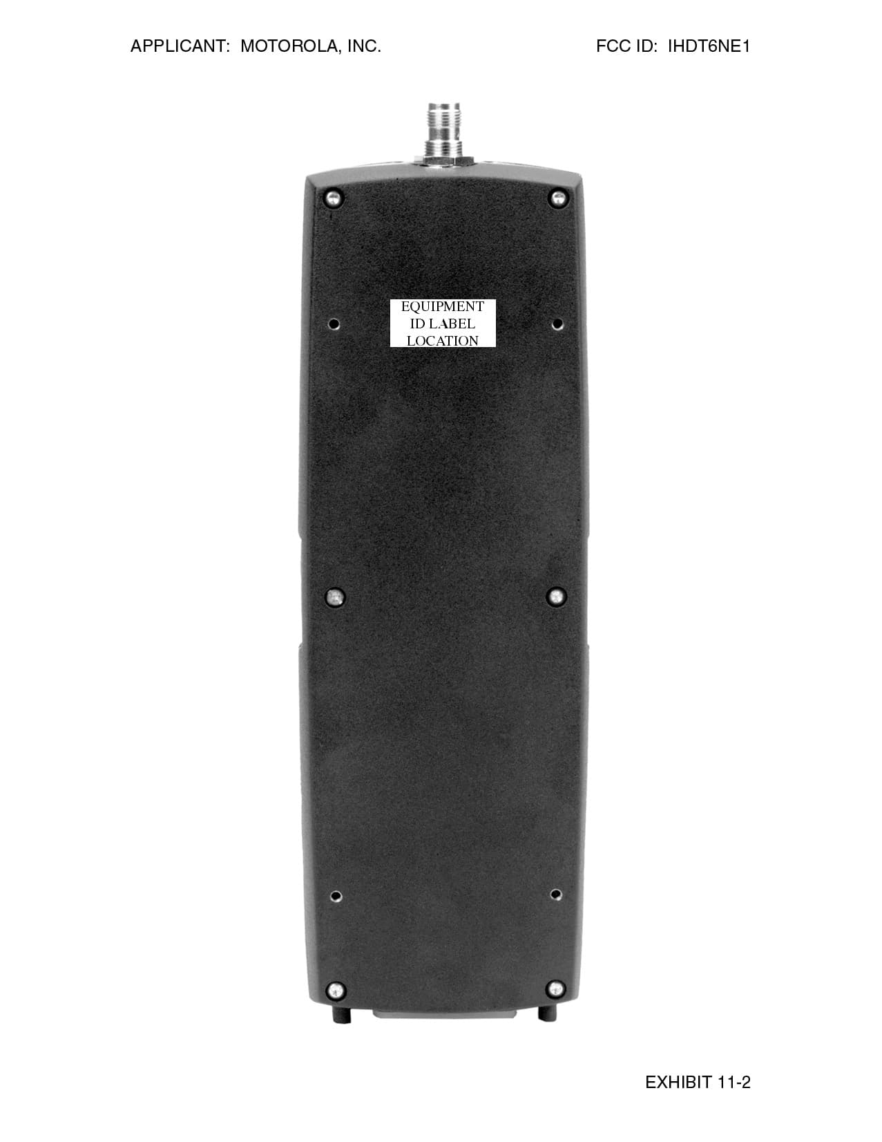
Click to zoom
Application Details
- Equipment Class
- TNB - Licensed Non-Broadcast Station Transmitter
- Date of Grant
- Nov 23, 1998
- Application Purpose
- Original Equipment
- Date of Application
- Sep 20, 1998
- Equipment Note
- Mobile Satellite Transceiver
- Frequency Range
- 1616.00000000 - 1626.00000000
- Company
- Motorola Mobility LLC
- Country
- United States
Documents & Files
Document Text
Text extracted from the exhibit documents filed with the FCC. Open a document above to read the original.
Users Manual
Welcome The future of global telecommunications is here—a satellite telephone, providing you with communication all over the world. The company that brought you the world’s first commercially available cellular phone has done it again! Motorola proudly introduces its Satellite Series™ 9520 Mobile Phone for the Iridium ® system. All Motorola wireless phones are designed and manufactured to meet Motorola’s exacting specifications and world-class quality standards. During development, our laboratory testing team took the durable phone through rigorous durability tests including temperature, humidity, shock, dust, vibration, and drop tests—and it still worked! We’re confident that the phone you purchased meets your own exacting standards. Thank you for choosing Motorola, a global leader in communications technology. Enjoy your new Satellite Series™ 9520 Mobile Phone! Mobile.book Page 1 Wednesday, September 9, 1998 3:05 PM Personal Communications Sector 600 North U.S. Highway 45 Libertyville, Illinois 60048 In the US & Canada: 1-888-839-4647 Outside the US & Canada (Toll-Free Global Number): +1-8000-839-4647 Direct Dial: +1-847-523-1898 TTY Toll-Free Number: 1-888-390-6456 TTY (outside the United States): +1-847-523-1841 Monday through Friday7AM to 7PM (CST) + designates international dialing access code , , VibraCall, and Satellite Series are registered trademarks of Motorola, Inc. Iridium, the Iridium logo, and Iridium World Service are registered trademarks and/or service marks of Iridium LLC. ©1998 Motorola, Inc. Printed in U.S.A. Mobile.book Page 2 Wednesday, September 9, 1998 3:05 PM iii Contents Welcome . . . . . . . . . . . . . . . . . . . . . . . . . . . . . . . . . . . . . . . . . . . . . . . 1 Safety Information . . . . . . . . . . . . . . . . . . . . . . . . . . . . . . . . . . . . . . . 7 Overview . . . . . . . . . . . . . . . . . . . . . . . . . . . . . . . . . . . . . . . . . . . . . . 11 Guide Overview . . . . . . . . . . . . . . . . . . . . . . . . . . . . . . . . . . . . . . 12 Phone Overview . . . . . . . . . . . . . . . . . . . . . . . . . . . . . . . . . . . . . . 14 Original Satellite Series Accessories . . . . . . . . . . . . . . . . . . . . . . 17 Using Your Phone . . . . . . . . . . . . . . . . . . . . . . . . . . . . . . . . . . . . . . 19 Installing the SIM Card . . . . . . . . . . . . . . . . . . . . . . . . . . . . . . . . . 20 Powering Up the Phone . . . . . . . . . . . . . . . . . . . . . . . . . . . . . . . . 21 Placing Calls . . . . . . . . . . . . . . . . . . . . . . . . . . . . . . . . . . . . . . . . . 23 Ending a Call . . . . . . . . . . . . . . . . . . . . . . . . . . . . . . . . . . . . . . . . 26 What’s My SIM Card Phone Number? . . . . . . . . . . . . . . . . . . . . . . 27 Receiving Calls . . . . . . . . . . . . . . . . . . . . . . . . . . . . . . . . . . . . . . . 28 Adjusting Earpiece Volume . . . . . . . . . . . . . . . . . . . . . . . . . . . . . . 30 Adjusting Ringer Volume . . . . . . . . . . . . . . . . . . . . . . . . . . . . . . . 31 Using In-Call Features . . . . . . . . . . . . . . . . . . . . . . . . . . . . . . . . . . . 33 Muting a Call . . . . . . . . . . . . . . . . . . . . . . . . . . . . . . . . . . . . . . . . . 34 Using Call Waiting . . . . . . . . . . . . . . . . . . . . . . . . . . . . . . . . . . . . . 35 Placing a Call on Hold . . . . . . . . . . . . . . . . . . . . . . . . . . . . . . . . . 36 Using the Menus . . . . . . . . . . . . . . . . . . . . . . . . . . . . . . . . . . . . . . . 39 Using the Options Menus . . . . . . . . . . . . . . . . . . . . . . . . . . . . . . . 40 Using the Quick Access Menu . . . . . . . . . . . . . . . . . . . . . . . . . . . 42 Using The In-Call Menu . . . . . . . . . . . . . . . . . . . . . . . . . . . . . . . . 44 Managing the Phone Book . . . . . . . . . . . . . . . . . . . . . . . . . . . . . . . 45 Entering the Phone Book Menu . . . . . . . . . . . . . . . . . . . . . . . . . . 46 What’s on the Phone Book Menu? . . . . . . . . . . . . . . . . . . . . . . . . 47 Organizing Your Phone Book . . . . . . . . . . . . . . . . . . . . . . . . . . . . 48 Storing Names and Numbers . . . . . . . . . . . . . . . . . . . . . . . . . . . . 50 Entering Names . . . . . . . . . . . . . . . . . . . . . . . . . . . . . . . . . . . . . . 52 Using Pauses in Numbers . . . . . . . . . . . . . . . . . . . . . . . . . . . . . . 54 Using Phone Number Prefixes . . . . . . . . . . . . . . . . . . . . . . . . . . . 55 Recalling Entries . . . . . . . . . . . . . . . . . . . . . . . . . . . . . . . . . . . . . . 56 Calling, Modifying, or Erasing an Entry . . . . . . . . . . . . . . . . . . . . 58 Checking Phone Book Capacity . . . . . . . . . . . . . . . . . . . . . . . . . . 59 Preventing Access to the Phone Book . . . . . . . . . . . . . . . . . . . . . 60 Restricting Phone Use . . . . . . . . . . . . . . . . . . . . . . . . . . . . . . . . . 61 Mobile.book Page iii Wednesday, September 9, 1998 3:05 PM iv Viewing the Last Ten Numbers Dialed . . . . . . . . . . . . . . . . . . . . .66 Viewing and Modifying Phone Numbers . . . . . . . . . . . . . . . . . . . .67 One-Touch Dialing . . . . . . . . . . . . . . . . . . . . . . . . . . . . . . . . . . . .68 Using Calling Features . . . . . . . . . . . . . . . . . . . . . . . . . . . . . . . . . .69 Entering the Call Related Features Menu . . . . . . . . . . . . . . . . . . .70 What’s on the Call Related Features Menu? . . . . . . . . . . . . . . . . .71 Forward Calls When Unavailable . . . . . . . . . . . . . . . . . . . . . . . . .72 Forward All Your Calls . . . . . . . . . . . . . . . . . . . . . . . . . . . . . . . . . .73 Detailed Call Forwarding . . . . . . . . . . . . . . . . . . . . . . . . . . . . . . .74 Cancel All Forwarding . . . . . . . . . . . . . . . . . . . . . . . . . . . . . . . . . .75 Showing Signal Strength . . . . . . . . . . . . . . . . . . . . . . . . . . . . . . . .76 Deactivating Pending Call Drop Signal . . . . . . . . . . . . . . . . . . . .77 Activ…
Text truncated - open the document above for the full version.
Users Manual
APPLICANT: MOTOROLA, INC. FCC ID: IHDT6NE1 EXHIBIT 7A DRAFT ANTENNA INSTALLATION GUIDELINE The following document is the Antenna Installation Guide for the Mobile Accessory Antenna. 1 SATELLITE SERIES MOBILE ACCESSORY ANTENNAS Installation Guideline Draft 2 1. Scope of Manual This document covers the procedures for installing the Satellite Series Mobile Antennas, both permanent mount and magnetic mounted versions. This manual is intended for use by experienced technicians familiar with installation of antennas for similar types of equipment. 2. How to use this Manual This manual covers the procedures for installing and mounting the Satellite Series Mobile Antennas, and for routing and connecting associated cabling. Before installing the 9520 Mobile Phone or it’s antenna, read the information related to installation planning and lightning/surge protection covered further in this manual. 3. General Safety Precautions During normal use, the Satellite Series 9520 Mobile Telephone will emit radio energy substantially below the level where any kind of harm is reported. However, to ensure personal safety and to avoid equipment damage, please observe the following simple rules: • To assure that radio frequency (RF) energy exposure to bystanders near the antenna is lower than that recommended by the adopted standard, operate the 9520 Mobile Phone only when bystanders are at least 60 cm (24 inches) away from a properly installed externally mounted antenna. • For proper Iridium system operation, do not operate 9520 Mobile Phone when someone is within 20 cm (8 inches) of the antenna. • DO NOT operate the telephone unless all RF connectors are secure and any open connectors are properly terminated. • DO NOT operate the 9520 Mobile Phone near electrical blasting caps or in an explosive atmosphere. • All equipment should be serviced and installed only by a qualified technician. • Refer to the appropriate section of the product service manual for additional pertinent safety information. 4. Installation Safety Warning When choosing a location for the 9520 Mobile Phone and the antenna, be sure to consider the operator and bystander’s safety. Be sure to mount the 9520 Mobile Phone and the antenna such that the General Safety Precautions outlined in Section 3 above are not violated during normal use by operators and bystanders. Be sure to route the cable between the 9520 Mobile Phone and the antenna in such a way that it does not pose an obstruction to the users. Take steps to insure that the antenna is mounted in such a way that it will not become detached from it’s supporting surface on the vehicle under normal conditions to which the vehicle will be subjected. 3 5. Operational Safety Warnings • WARNING - For vehicles equipped with electronic anti-skid systems, see “ANTI-SKID BRAKING PRECAUTIONS” Publication, Motorola Number 68P81109E34. • WARNING - For vehicles equipped with electronic ignition systems, check the service manual for warnings about the use of radiotelephone equipment in the vehicle. • WARNING - It is mandatory that radiotelephone installations in vehicles, fueled by liquefied petroleum gas, conform to the following standard: National Fire Protection Association standard NFPA 58 applies to radio installations in vehicles fueled by liquefied petroleum (LP) gas with LP gas container in the trunk or other sealed-off space within the interior of the vehicles. This standard requires that: 1. Any space containing radio equipment shall be isolated by a seal from the space in which the LP gas container and its fittings are located. 2. Remote (outside) fitting connections shall be used. 3. The container space shall be vented to the outside. • Airbag Warning Statement Installation of vehicle communication equipment should be performed by a professional installer/technician qualified in the requirements for such installations. An air bag’s size, shape and deployment area can vary by vehicle make, model and front compartment configuration (e.g., bench seat vs. bucket seats). Contact the vehicle manufacturer’s corporate headquarters, if necessary, for specific air bag information for the vehicle make, model and front compartment configuration involved in your communication equipment installation. WARNING--VEHICLES EQUIPPED WITH AIR BAGS An air bag inflates with great force. DO NOT place objects, including communication equipment, in the area over the air bag or in the air bag deployment area. If the communication equipment is improperly installed and the air bag inflates, this could result in serious bodily harm to vehicle occupants. 5. Antenna Installation Planning The Satellite Series Mobile Antenna system consists of a mobile antenna and a coaxial cable that connects the 9520 Mobile Phone to the antenna . It is suitable for both vehicular and marine applications, and is designed to meet Iridium system performance requirements when installed per this manual. A typical vehicular application is depicted in the Diagram “A” below. The Satellite Series Mobile Antenna is a “patch” type antenna contained inside a weatherproof housing, and is intended to be mounted on a horizontal conductive surface. For proper performance in the Iridium system, the antenna must have a clear view of the sky from the horizon on up and must be mounted horizontally. It’s location should be such that at least 40 cm (15.8 in.) of conductive horizontal surface extends in all directions from the center of the antenna, and the antenna should be located on the highest horizontal surface on the vehicle. In almost all vehicles, these requirements are best satisfied by mounting the antenna at the center of the roof. Some vehicles have a large trunk lid that provides a suitable antenna location, but this location is only desirable if the roof fails to provide the adequate conductive surface needed 4 As depicted in Diagram “A”, the connection between the Satellite Series Mobile Antenna and the 9520 Mobile Phone is accomplished using the at…
Text truncated - open the document above for the full version.
Users Manual
APPLICANT: MOTOROLA, INC. FCC ID: IHDT6NE1 EXHIBIT 7B DRAFT ANTENNA INSTALLATION GUIDELINE The following document is the Antenna Installation Guide for the Fixed Site Accessory Antenna. 1 SATELLITE SERIES FIXED SITE ACCESSORY ANTENNA Installation Guideline Draft 2 1. Scope of Manual This document covers the procedures for installing the Satellite Series Fixed Site Antenna, and the it’s optional cable system, and is to be used with the Satellite Series 9520 Mobile or Satellite Series 9570 Portable Dock. This manual is intended for use by experienced technicians familiar with installation of antennas for similar types of equipment. 2. How to use this Manual This manual covers the procedures for installing and mounting the Fixed Site Antenna, for routing and connecting associated cabling, and for dealing with lightning and surge suppression. Before installing the 9520 Mobile Phone or 9570 Portable Dock or it’s antenna, read the information related to installation planning and lightning/surge protection covered further in this manual. 3. General Safety Precautions During normal use, the Satellite Series portable telephone will emit radio energy substantially below the level where any kind of harm is reported. However, to ensure personal safety and to avoid equipment damage, please observe the following simple rules: • To assure that radio frequency (RF) energy exposure to bystanders near the antenna is lower than that recommended by the adopted standard, operate the 9520 Mobile Phone or 9570 Portable Dock only when bystanders are at least 60 cm (24 inches) away from a properly installed externally mounted antenna. • For proper Iridium system operation, do not operate 9520 Mobile Phone or 9570 Portable Dock when someone is within 20 cm (8 inches) of the antenna. • DO NOT operate the telephone unless all RF connectors are secure and any open connectors are properly terminated. • DO NOT operate the 9520 Mobile Phone or 9570 Portable Dock near electrical blasting caps or in an explosive atmosphere. • All equipment should be serviced and installed only by a qualified technician. • Refer to the appropriate section of the product service manual for additional pertinent safety information. 4. Installation Safety Warning When choosing a location for the 9520 Mobile Phone or 9570 Portable Dock and the antenna, be sure to consider the operator and bystander’s safety. Be sure to mount the 9520 Mobile Phone or 9570 Portable Dock and the antenna such that the General Safety Precautions outlined in Section 3 above are not violated during normal use by operators and bystanders. Be sure to route the cable between the 9520 Mobile Phone or 9570 Portable Dock and the antenna in such a way that it does not pose an obstruction to the users. Take steps to insure that the antenna is mounted in such a way that it will not become detached from it’s supporting structure under normal external forces. 3 5. Antenna Installation Planning The Satellite Series Fixed Site Antenna system consists of a fixed mount antenna and a coaxial cable that connects the 9520 Mobile Phone or 9570 Portable Dock to the antenna . It is suitable for both marine and terrestrial applications, and is designed to meet Iridium system performance requirements when installed per this manual. A typical terrestrial application is depicted in the Diagram “A” below. The Satellite Series Fixed Site Antenna is a helical antenna contained inside a weatherproof housing, and is intended to be mast mounted without a ground plane of any type. It’s location should be reasonably clear of nearby metal obstructions and such that a distance of at least 20 cm is maintained between the antenna and the user. For proper performance in the Iridium system, the antenna must have a clear view of the sky from the horizon on up and must be mounted vertically. While horizontal obstructions may not be totally avoidable, they should be minimized, for they may result in a spot(s) of poor system coverage. This will decrease or possibly eliminate the ability to operate the Iridium Satellite Series portable phone unit at times which are not predictable by the user. The connection between the Satellite Series Fixed Site Antenna and the 9520 Mobile Phone or 9570 Portable Dock is accomplished using specialized coaxial cable system. This cable system is offered as an option to the Fixed Site Antenna. Alternatively, the user can choose cables from other suitable sources, following the guidelines outlined further in this manual. To minimize the loss of radio signal from the antenna to the 9520 Mobile Phone or 9570 Portable Dock, the coaxial cable system between those two components should be as low loss as possible. Listed below in Table One are a selection of coaxial cables available from Times Microwave Fixed Site Antenna 8.5 meter Main Coaxial Cable High Frequency Surge Suppressor Antenna Support Structure Satellite Series Portable Phone or Portable Dock 0.5 meter "Jumper" Coaxial Cable 1.5 meter "Jumper" Coaxial Cable Diagram A--Typical Fixed Antenna and Cable Installation ( Dwelling) 4 (Wallingford, Conneticut, USA. Telephone 203-949-8400). The second cable listed in this table is part of the optional Satellite Series Antenna Cable kit. The other cables listed are also available from Times Microwave, and are provided for reference in those applications where longer cable runs are needed. All cable configurations in Table One are designed to meet Iridium system requirements. Table One—Maximum Cable Lengths and Types Times Microwave Cable Type Loss (dB/m) Max. Length (m) Max. length (ft) LMR 240 0.3373194.514.7 LMR 400 0.1753638.528(Part of Antenna Cable Kit) LMR 600 0.11362313.244 LMR 900 0.07689319.765 LMR 1200 0.05787226.286 LMR 1700 0.04346135115 1.625" LDF 0.03603742138.3 2.25" LDF 0.03026050.2164.7 Other configurations of cables besides those listed in Table One can be used as long as the total insertion loss for the entire cable run (including any lighting arrest…
Text truncated - open the document above for the full version.
Attestation Statements
APPLICANT: MOTOROLA, INC.FCC ID: IHDT6NE1 EXHIBIT 1 STATEMENT OF CERTIFICATION The technical data supplied with this application, having been taken under my supervision is hereby duly certified. The is a statement of my qualifications: BSEE 1984 Northwestern University, Evanston, Illinois MSEE 1991 Illinois Institute of Technology, Chicago, Illinois 14 years experience in engineering design, 8 years experience in Cellular Radiotelephone and Systems Design SIGNATURE: NAME:John D. Pradal DATE:10/01/98 POSITION:Engineering Manager I hereby certify that the above application was prepared under my direction and that to the best of my knowledge and belief, the facts set forth in the application and accompanying technical data are true and correct. SIGNATURE: NAME:Martin Seitz DATE:10/01/98 POSITION:Sr. Resource Manager
Cover Letter(s)
September 21, 1998 CONFIDENTIALITY REQUEST CONTAINED WITHIN Federal Communications Commission Authorization and Evaluation Division 7435 Oakland Mills Road Columbia, Maryland 21046 Re:Application for Portable Satellite Transceiver Type Acceptance Gentlemen: Motorola, Inc., Cellular Subscriber Sector, 600 N. U.S. Highway 45, Libertyville, Illinois 60048-5343 herein submits "Electronic" Application for Equipment Authorization (to be followed by submission of Check Number 120-661955 in the amount of $610.00 along with Form 159) for Certification of a Mobile Satellite Transceiver under FCC Rule Part 25, FCC ID: IHDT6NE1. Motorola is also the manufacturer of this equipment. This application is submitted in accordance with the Interim Provisions for Equipment Authorization (Certification) of GMPCS equipment specified in FCC GEN Docket No. 98- 68; adopted May 14, 1998, released May 18, 1998 and published in the Federal Register June 10, 1998. In addition to confidentiality for the entire application prior to grant (per 47CFR0.457(d)(1) (ii) ), Motorola requests, pursuant to 47CFR0.459, post-grant confidentiality for portions of the material contained in this application such that the identified material will be withheld from public inspection following the grant of this authorization. This material, as indicated by request for confidentiality of the items during the electronic submission process and further identified by their listing in RED on the List of Exhibits attached hereto, includes: Motorola Exhibit 4, Radio Semiconductor List (submitted as 'Parts List/Tune Up Info,' EAS Exhibit #10); Motorola Exhibit 5, Circuit Diagrams (consisting of and submitted as two parts, one as Exhibit 5ABC, 'Block Diagrams,' EAS Exhibit #4, and the other as Exhibit 5D, 'Schematics,' EAS Exhibit #5); and Motorola Exhibit 6, Circuit Descriptions (submitted as 'Operational Description,' EAS Exhibit #12). Specifically, these exhibits contain information relating to circuit function and complexity that could be of benefit to competitors. This material contains Motorola's trade secrets and confidential information that Motorola does not customarily release to the public and which is otherwise not generally available to the public. Federal Communications Commission Authorization and Evaluation Division 7435 Oakland Mills Road Columbia, Maryland 21046 September 21, 1998 Page 2 Please contact me by telephone at (847) 523-7373, by facsimile at (847) 523-2350 or by correspondence at the address herein if there are any further questions or additional information needed concerning this filing. Regards, (signed) John A. Kalenowsky FCC Liaison Cellular Subscriber Sector 600 N. U.S. Highway 45 Libertyville, IL 60048-5343 Enclosures APPLICANT: MOTOROLA, INC.FCC ID: IHDT6NE1 LIST OF EXHIBITS EXHIBITDESCRIPTIONFCC REFERENCE _____________________________________________________________________ 1CERTIFICATION OF DATA2.911 2GENERAL INFORMATION PRODUCTION PLANS2.983-C APPLICATION REFERENCES2.1061 DATA SUBMITTAL PROCEDURE2.947 SIMILAR APPLICATIONS 3DESCRIPTION TECHNICAL CHARACTERISTICS2.983-D-1-5 APPLICATION 4*RADIO SEMICONDUCTOR LIST2.983-D-6 5*CIRCUIT DIAGRAMS2.983-D-7 6*CIRCUIT DESCRIPTION INDEX2.983-D-10-11-12 6A*MEANS FOR FREQUENCY STABILIZATION 6B*MEANS FOR ATTENUATION OF SPURIOUS EMISSIONS 6C*MEANS FOR LIMITING MODULATION 6D*MEANS FOR ATTENUATION OF HIGHER AUDIO FREQUENCIES 6E*MEANS FOR LIMITING POWER OUTPUT 6F*DIGITAL MODULATION TECHNIQUES 7INSTRUCTION MANUAL2.983-D-8 8TRANSCEIVER ADJUSTMENTS2.983-D-9 9MEASURED DATA (INDEX)2.983-E 9ARF OUTPUT MEASURED DATA2.985 9BOCCUPIED BANDWIDTH-GRAPH2.989 9C-1,2,3FCC CONDUCTED SPURIOUS EMISSIONS-GRAPH2.991 9DFCC RADIATED SPURIOUS EMISSIONS-GRAPH2.993 9EFREQUENCY STABILITY VS TEMP-GRAPH2.995 9FFREQUENCY STABILITY VS VOLTAGE-GRAPH2.995 9G-1,2TBR41 CONDUCTED SPURIOUS OUT-OF-BAND EMISSIONS-GRAPHS 9HTBR41 RADIATED SPURIOUS EMISSIONS-GRAPH 9ITBR41 CONDUCTED EMISSIONS CARRIER OFF 9J-1,2,3,4TBR41 IN-BAND CONDUCTED EMISSIONS 9KTBR41 EIRP DENSITY MEASUREMENT 10IDENTIFICATION (NAMEPLATE) INFORMATION2.983-F 11-1,2,3,4PHOTOGRAPHS2.983-G 12MEASUREMENT TECHNIQUES * In RED indicates submitted with Request for Post-Grant Confidentiality. Also, please note, rule sections listed in the "FCC REFERENCE" column are to "Type Acceptance" rules, prior to implementation of ET Docket 97-94.
ID Label/Location Info
APPLICANT: MOTOROLA, INC.FCC ID: IHDT6NE1 EXHIBIT 10 FCC ID: IHDT6NE1 The Equipment ID label above is representative (in size and in showing the FCC Identifier as it will appear) of the label that is presently planned to appear on the equipment when in production. Its planned location is shown in Exhibit 11-2.
Operational Description
APPLICANT: MOTOROLA, INC.FCC ID: IHDT6NE1 EXHIBIT 2-1 GENERAL INFORMATION 1. Production Plans---Pursuant 2.983 (c) Quantity production is planned. 2. Application References---Pursuant 2.1061 Reference is made to the following Motorola “Application References on file with the Commission: None 3. Data Submittal Procedure: Data is supplied in accordance with Part 2, Sub-part J of the Commission’s rules. Standards used on measurements supplied are: ETSI TBR41 and section 47CFR25.202. 4. Similar to “Currently Type Accepted Transmitter Type(s)” IHDT6ND1, which uses the same basic transceiver as this unit. 5. Report of measurements pertaining to types of emission, frequency range, maximum output power and modulation techniques. A. Types of emission The pertinent emission designator for the mobile satellite phone is 41K7Q7W, as explained in paragraph 6 of this exhibit. Actual measurements of Occupied Bandwidth are shown in Exhibit 9B. Spurious Emissions (Conducted and Radiated) are reported in Exhibits 9C, 9D (unique FCC requirements), 9H and 9J (European TBR41 standards). B. Frequency Range The frequency range of the equipment is in the band of 1616 MHz to 1626 MHz, in accordance with the Technical Basis for Regulation (TBR41) of Satellite Personal Communications Networks (S-PCN) for Mobile Earth Stations (MESs) in the 1.6/2.4 GHz bands. APPLICANT: MOTOROLA, INC.FCC ID: IHDT6NE1 EXHIBIT 2-2 Frequency Stability versus temperature and voltage measurements are shown in Exhibits 9E and 9F. This equipment uses Automatic Frequency Control (AFC) to lock within +/- 600 Hz of the received frequency from the Space Vehicle (SV). The mobile performs all frequency pre-correction for Doppler shifts. The system is designed to be tolerant of these frequency offsets. C. Maximum Output Power: Radio Frequency Output Power ranges from 0.1 to 0.6 Watts. The mobile maximum output power is achieved under closed loop control with the SV network. The mobile power will respond to commands from the SV network to change power levels as defined in the specifications. RF Output Power Measurements are shown in Exhibit 9A. D. Modulation Techniques Modulation is DEQPSK (Differentially Encoded Quadrature Phase Shift Keying) Exhibits 6C and 6D further discuss details of the modulating circuitry. Exhibit 6F discusses digital modulation techniques. 6. Determination of Emission Designator for the portable satellite transceiver (per Part 2-Subpart C of the commission’s rules) A. Emission, modulation and transmission characteristics (per section 2.201) a. First Symbol - Type of Modulation of the main carrier. The main carrier is pulsed in a TDMA format, utilizing Differentially Encoded Quadrature Phase-Shift Keying (DEQPSK) techniques. This corresponds to symbol Q, associated with the carrier being “angle modulated during the period of the pulse.” b. Second Symbol - nature of signal(s) modulating the main carrier. In-phase (I) and Quadrature (Q) modulating signals representing sampled, quantized voice or other audio information or data, modulates the main carrier. APPLICANT: MOTOROLA, INC.FCC ID: IHDT6NE1 EXHIBIT 2-3 This corresponds to symbol 7, derived from two channels “containing quantized or digital information” modulated in-phase and quadrature modulated. c. Third Symbol - Type of information to be transmitted. The information transmitted is a combination of data transmission (command data) and telephony (sample quantized voice or other audio signals). This corresponds to W, defined as “combinations of above” which would be the combination of the symbol D, “Data transmission, telemetry, telecommand”, and symbol E, “Telephony (including sound broadcasting)”. B. Bandwidths (per section 2.202) Bandwidth is primarily determined by a 96 tap FIR filter used to filter I and Q channel modulating signals and is consistent with a necessary bandwidth specification of 41.667 kHz. Converting this result, using the format indicated in paragraph 2.202(a), yields 41K7. The resulting complete emission designator is then 41K7Q7W . APPLICANT: MOTOROLA, INC.FCC ID: IHDT6NE1 EXHIBIT 3 DESCRIPTION 1. Transmitter Technical Characteristics - Pursuant 2.983(d) A. RF Power Output: Variable range from 0.1 to 0.6 Watts (by control of satellite network via closed loop power control). The transmitter duty cycle allows for bursted transmission every 8.28 ms out of 90 ms, or 9.2%, at a rate of 50 kbps, or 25 k symbols/sec. B. Frequency Range: 1616 MHz to 1626 MHz C. Frequency Stability: +/- 0.00015 % (1.5 ppm) D. Emissions: 41K7Q7W E. D.C. Voltage into the Final RF Amplifier: 7.5 Volts DC, nominal D.C. Current into the Final RF Amplifier: 0.404 Amps (time averaged current with a 9.2% duty cycle). 2. Transmitter Application A. Power Supply Available The transmitter is normally operated by means of a 7.75 V nominal regulated DC voltage, boosted from the nominal 4.4 V DHFA supply voltage utilized by the transceiver. The supply range afforded by the DHFA is 4.2 - 4.6 V DC. B. Antenna Available The transceiver is provided with a standard RF connection designed to interface with a 50 Ohm characteristic impedance. The radio transmitter is designed to be used with an external (permanent or magnetic mount), Right- Hand Circularly Polarized patch antenna. The antenna provides near hemispheric coverage, and omni-directional gain pattern. C. Maximum Transmit Channel Capacity 240 Channels
Operational Description
APPLICANT: MOTOROLA, INC. FCC ID: IHDT6NE1 In response to the FCC question concerning EIRP. The FCC asked: "As this unit has an RF connector which supplied either a fixed or mobile antenna, please provide EIRP measurement for both configurations" Mobile Patch Antenna Cable(dB) * Net Gain Tx Conducted EIRP (W) Freq(MHz) Gain (dBi) Losses dB Power Out (dBm) 1616 0.07 1.7 -1.63 27.8 0.41 1621 0.26 1.7 -1.44 27.8 0.43 1626 0.37 1.7 -1.33 27.8 0.44 Fixed Site Helix Antenna Cable(dB) * Net Gain Tx Conducted EIRP (W) Freq(MHz) Gain(dBi) Losses dB Power Out (dBm) 1616 0.15 2.2 -2.05 27.8 0.38 1621 0.21 2.2 -1.99 27.8 0.38 1626 0.25 2.2 -1.95 27.8 0.39 * Estimated minimum loss
RF Exposure Info
1 1 November 13, 1998 RF Exposure Evaluation Report for Motorola mobile satellite transceiver (FCC ID IHDT6NE1). Prepared by: Paul Moller, Principal Staff Engineer Motorola Personal Communications Sector Product Safety Laboratory Libertyville, Illinois The Motorola Personal Communications Sector Product Safety Laboratory has evaluated the IRIDIUM Satellite Series 9520 product, FCC ID IHDT6NE1, for the need to conduct RF exposure testin…
Text truncated - open the document above for the full version.
Contact Information
Applicant
Jeff Narducci(Director Product Compliance)
Technical Specifications
| # | Rule Parts | Frequency Range | Power Output | Emission | Tolerance |
|---|---|---|---|---|---|
| 1 | 25 | 1.62 GHz - 1.63 GHz | 600.00 mW | 41K7Q7W | 1.0000000000 ppm |
Other Applications from Motorola Mobility LLC
IHDT56AW9
May 12, 2026Smart Watch
Equipment Class
NII - Unlicensed National Information Infrastructure TXIHDT56AW5
Apr 08, 2026Mobile Cellular Phone
Equipment Class
DTS - Digital Transmission SystemIHDT56AW6
Mar 18, 2026Smart Watch
Equipment Class
JBP - Part 15 Class B Computing Device PeripheralIHDT56AX4
Mar 17, 2026Mobile Cellular Phone
Equipment Class
PCE - PCS Licensed Transmitter held to earIHDT56AW3
Mar 03, 2026Mobile Cellular Phone
Equipment Class
6XD - 15E 6 GHz Low Power Indoor Client