IHDT6NJ1Satellite Transceiver - Mobile
Motorola Mobility LLC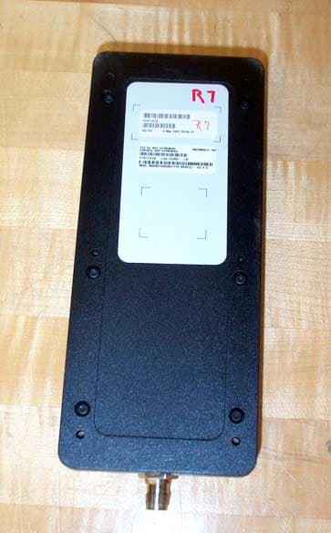
Click to zoom
Application Details
- Equipment Class
- TNB - Licensed Non-Broadcast Station Transmitter
- Date of Grant
- Apr 25, 2002
- Application Purpose
- Original Equipment
- Date of Application
- Apr 25, 2002
- Equipment Note
- Satellite Transceiver - Mobile
- Frequency Range
- 1616.00000000 - 1626.50000000
- Company
- Motorola Mobility LLC
- Country
- United States
Documents & Files
Document Text
Text extracted from the exhibit documents filed with the FCC. Open a document above to read the original.
Users Manual
PRELIMINARY DRAFT .SHEET 1 Motorola Satellite Series 9522 L-Band Transceiver Fact Sheets PRELIMINARY DRAFT .SHEET 2 Motorola Satellite Series 9522 L-Band Transceiver Fact Sheets 1 Product Overview The 9522 LBT is intended for incorporation into a final Iridium subscriber product that would supply power, provide an antenna, and provide user interface components such as a keypad, display, microphone, and speaker. If the final product supports a data mode, an RS232 data interface would also be included. Regulatory approval for FCC, Canada and CE will be provided for the 9522 LBT assuming an antenna with a gain of≤3 dBi. This will allow the 9522 LBT to be integrated into a variety of subscriber products, as well as retrofitted into existing LBT-based subscriber products. These products, when integrated together will require Regulatory testing. The functional capabilities of the 9505 handset provide the baseline for the 9522 LBT, noting that user interface components must be added to the 9522 LBT in order to access such functionality. The ISU AT Command Referenceand the Satellite Series 9505 Portable Telephone User’s Guideprovide information relevant to the 9522 LBT’s functional capabilities. The following differences exist when comparing the functional capabilities of the 9522 LBT to the 9505 handset. • The 9522 LBT is always powered externally and therefore has no battery metering. • The 9522 LBT does not incorporate a vibrating call alert and therefore has no vibrate/ring control. • The 9522 LBT incorporates an analog audio interface not present on the 9505 handset. 2 Standards Compliance The 9522 LBT has been designed to comply with the standards for Emissions Compliance, Electromagnetic Compatibility, Electromagnetic Safety, and AC Safety in the United States, Europe and Canada. Standards in other areas of the world are often the same. 2.1 FCC Compliance This device has been certified under 47 CFR Part 25 as FCC ID: IHDT6NJ1 and also complies with Part 15 of the FCC Rules. Operation is subject to the condition that this device does not cause harmful interference. Any changes or modifications, including the use of a non-standard antenna, not expressly approved by the party responsible for compliance could void the user's authority to operate the equipment. IMPORTANT: To comply with FCC RF exposure requirements, a minimum separation of 20 cm is required between the antenna and all persons. 2.2 CE Compliance This product, when marked with the CE symbol, complies with the European Community Council Directive for R&TTE, 99/5/EC, provided the installer/user adheres to the instructions detailed in the Interface specification .This product is in compliance with applicable ETSI standards. Compliance with the requirements of ETSI EN 301 489 requires the use of a shielded digital data interface cable. PRELIMINARY DRAFT .SHEET 3 3 Physical Specifications The 9522 LBT is depicted inFigure 1below. Figure 1: Top View 3.1 Environmental The environmental specifications of the 9522 LBT are summarized inTable 1below. Table 1: Environmental Specifications ParameterValue Operating Temperature Range-20°C to +60°C Operating Humidity Range ≤85% RH Storage Temperature Range-40°C to +85°C Storage Humidity Range ≤85% RH 3.2 Dimensions The overall dimensions of the 9522 LBT and its weight are summarized inTable 2below. Dimensioned views of the 9522 LBT are shown inFigures 2-5to follow. Table 2: Mechanical Dimensions ParameterValue Length (including antenna connector)216.1 mm (8.51") Length (excluding antenna connector)196.4 mm (7.73") Width82.6 mm (3.25") Depth39.0 mm (1.54") Weight (approximate)610 g PRELIMINARY DRAFT .SHEET 4 Figure 2: Side View Figure 3: Bottom View PRELIMINARY DRAFT .SHEET 5 Figure 4: Antenna Connector End View Figure 5: Multi-Interface Connector End View 3.3 Interface Connectors The 9522 LBT incorporates three interface connectors. • Multi-Interface Connector (located on the end of the 9522 LBT) • Antenna Connector (located on the end of the 9522 LBT; opposite to the multi-interface connector) • Subscriber Identity Module (SIM) Chip Connector (located beneath a cover plate atop the 9522 LBT) PRELIMINARY DRAFT .SHEET 6 3.3.1 Multi-Interface Connector The multi-interface connector is a 25 pin D-subminiature type that includes four interfaces. • DC Power • Control/Audio • RS232 Data • Analog Audio 3.3.2 Antenna Connector The 9522 LBT provides a single, 50Ω, TNC type antenna connector for both transmit and receive. 3.3.3 SIM Chip Connector An integrated SIM chip connector is provided on the 9522 LBT. This connector allows installation of the chip form of the SIM beneath a cover plate on the 9522 LBT housing. 4 Electrical Interfaces The subsections to follow contain interface information for the electrical interfaces of the 9522 LBT. 4.1 DC Power Interface 4.1.1 DC Power Interface Signal Descriptions The DC power interface is comprised of the DC power inputs and a control signal as summarized inTable 3below. The EXT_B+ and GND inputs are used to supply DC power to the 9522 LBT. The EXT_ON_OFF control input is pulled to a GND level to toggle the 9522 LBT on and off. Table 3: Control/Audio Interface Signal Descriptions Signal NameSignal Description EXT_B+External 4.4 VDC input GNDExternal GND input EXT_ON_OFFPower on/off control input PRELIMINARY DRAFT .SHEET 7 4.1.2 DC Power Input Specifications The DC power requirements for the 9522 LBT are summarized inTable 4below. Note that these requirements apply to DC power measured at the 9522 LBT multi-interface connector input. Table 4: DC Power Input Specifications ParameterValue Main Input Voltage - Range+4.0 VDC to +4.8 VDC Main Input Voltage - Nominal4.4 VDC Main Input Voltage - Ripple40 mVpp Peak Input Current (maximum)2.5 A @ 4.4 VDC Main Input Active Power (average)2500 mW Main Input Standby Power (average)210 mW 4.2 Control/Audio Interface 4.2.1 Control/Audio Interface Signal Descriptions The control/audio interface enables peripherals such as hand…
Text truncated - open the document above for the full version.
Attestation Statements
Exhibit 2 Page 1 of 1FCC ID: IHDT6NJ1 3/29/02 Exhibit 2 – Attestation Statement IRIDIUM SUBSCRIBER UNIT (ISU) - MOBILE FCC ID: IHDT6NJ1 Model No. 9522 (Sebring) 2.0Attestation Statement The technical data supplied with this application, having been taken under my supervision, is hereby duly certified. This is a statement of my qualifications: BSEE 1982, Northern Arizona University, Flagstaff, Arizona NARTE Certified EMC Engineer, 12 years 17 years experience in EMC Engineering design and test Signature: Name:Gil Estrella Date:4/1/02 Position:Sr. Staff Engineer I hereby certify that the above application was prepared under my direction and that to the best of my knowledge and belief, the facts set forth in the application and accompanying technical data are true and correct. Signature: Name:Dwayne Awerkamp Date:4/1/02 Position:EMC Department Manager
Cover Letter(s)
CONFIDENTIALITY REQUEST CONTAINED WITHIN 3 April 2001 Intertek Testing Services (ITS), Inc. 70 Codman Hill Road Boxborough, MA 01719 Attention: Mr. Roland Gubisch Re: Application for IRIDIUM Subscriber Unit (ISU), Model No. 9522 (47 CFR Part 25) FCC ID: IHDT6NJ1 Motorola, Inc., 600 North US Highway 45, Libertyville, Illinois 60048 herein submits this application for Equipment Authorization under FCC Rule Part 25, for Satellite Transceiver,FCC ID: IHDT6NJ1. This application is being submitted to ITS under the FCC Public Notice, DA 00-1223, allowing Telecommunication Certification Bodies (TCB) to certify specific equipment including Licensed Radio Service Equipment under Scope B1. Motorola, Inc. manufactures the IRIDIUM Satellite Series Model No. 9522. In addition to confidentiality for the entire application prior to grant (per 47CFR0.457(d)(1)(ii)), Motorola requests, pursuant to 47CFR0.459, post-grant confidentiality for identified sections of the filing material contained in this application with this material being withheld from public inspection following the grant of this authorization. This material includes Exhibit 4 (Block Diagrams), Exhibit 5 (Schematic Diagrams), Exhibit 10 (RF Transceiver Parts List), and Exhibit 12 (Operational Description).Specifically, these exhibits contain information relating to circuit function and complexity that could be of benefit to competitors. This material contains Motorola trade secrets and confidential information that is not customarily released or generally available to the public. The GDDS EMC Group is acting as an authorized representative and technical contact for this filing. Please contact me by telephone at (480) 441-3725, by facsimile at (480) 441-3625, or by email at [email protected] there are any questions or additional information needed regarding this filing. Sincerely, Gil Estrella EMC Engineer GDDS
Cover Letter(s)
From: Estrella Gil-P19838 [[email protected]] Sent: Friday, April 26, 2002 2:11 PM To: '[email protected]' Cc: Danielle Gravelle (E-mail) Subject: RE: Sebring FCC ID: IHDT6NJ1 Roland, In response to your comments below: Administrative 1) The Interface Specification provided under Exhibit 8 is the only documentation provided with the L-Band Transceiver. This specification has recently been updated to include the RF Exposure information and is attached for your review. 2) You are correct, the actual emission designator should be 41K7Q7W. I apologize for the error. 3) Attached is a revised Exhibit 1 with a photo of the actual label including the FCC identifier. Technical 1) That is correct, the average power is derived from the 9.2% duty cycle as noted. 2) The antenna information is attached as "9522_Ant_Info.pdf". The attachment includes the pages from the Iridium Accessory brochure indicating the maximum gain for each antenna type used to derive the expected EIRP levels shown on the first page. The use of any of these antennas does not rely on specific attenuation of the connecting cable to meet the maximum power requirements. The estimated minimum cable losses are shown in the table. I hope these responses adequately address your questions and comments. Thank you very much and let me know if you have further questions. Regards, Gil Estrella GENERAL DYNAMICS Decision Systems 8201 E. McDowell Rd. M/S H2550 Scottsdale, AZ 85252 Phone: 480-441-3725 Pager: 602-360-4001 Fax: 480-441-3625 EMail: [email protected] -----Original Message----- From: [email protected] [mailto:[email protected]] Sent: Thursday, April 25, 2002 4:16 PM To: [email protected] Cc: [email protected] Subject: Sebring FCC ID: IHDT6NJ1 Gil: Technical review of your application is complete, and the device appears to meet the requirements for certification. However, we note the following: Administrative 1) I cannot find a user manual (installation and operating instructions). This would also contain any RF exposure information. Please indicate where it is located, or provide. 2) The emission designator in the Form 731 is given as 47K7Q7W. This is clearly incorrect, as the test report and Operational Description justify a designator of 41K7Q7W. We will amend the Form 731 Form here for filing purposes. 3) The FCC ID: label is shown as "FCC ID: Not approved." A facsimile of the final intended label, with the correct FCC identifier, is needed. Technical 1) The RF conducted power output is described as 0.1 - 0.645W average, 7W peak. The Operational description refers to a transmission burst 8.28 ms every 90 ms, for a duty cycle of 9.2%. Applying the 9.2% duty cycle to 7W results in an average of 0.644W. Is this how the relationship between average and peak power is determined? 2) The power limits in Part 25 are given in terms of eirp power density. Please provide antenna gain information for the patch and mast antennas, to assess compliance where only conducted measurements are provided. Please provide commercial specifications, if available. If the use of the remote patch antenna relies on specific attenuation of the connecting cable, please provide information on the attenuation required. Thank you, Roland Gubisch ITS
Cover Letter(s)
Antenna Gain Information: (Source: Motorola Iridium, Satellite Series, Accessory brochure) Portable Auxiliary Patch Frequency (MHz) Maximum Antenna Gain (dBi) Est. Minimum Cable Loss (dB) Net Gain Transmit Conducted Power Out (dBm) EIRP (W) 1616 - 16260.50.4+0.128.10.66 Mobile Magnetic Mount Frequency (MHz) Maximum Antenna Gain (dBi) Est. Minimum Cable Loss (dB) Net Gain Transmit Conducted Power Out (dBm) EIRP (W) 1616 - 16261.01.3-0.328.10.60 Fixed Site Helix Frequency (MHz) Maximum Antenna Gain (dBi) Est. Minimum Cable Loss (dB) Net Gain Transmit Conducted Power Out (dBm) EIRP (W) 1616 - 16261.51.8-0.328.10.60
External Photos
Exhibit 3 Page 1 of 2FCC ID: IHDT6NJ1 3/29/02 Exhibit 3 – External Photographs IRIDIUM SUBSCRIBER UNIT (ISU) - MOBILE FCC ID: IHDT6NJ1 Model No. 9522 (Sebring) 3.0External Photos Figure 3.0-1 Sebring External View - Front Exhibit 3 Page 2 of 2FCC ID: IHDT6NJ1 3/29/02 Figure 3.0-2 Sebring External View - Rear
ID Label/Location Info
Exhibit 1 RevA Page 1 of 2FCC ID: IHDT6NJ1 4/26/02 Exhibit 1 – ID Label Information IRIDIUM SUBSCRIBER UNIT (ISU) - MOBILE FCC ID: IHDT6NJ1 Model No. 9522 (Sebring) 1.0Identification (Nameplate) Information Figure 1.0-1 Sebring FCC Sample labels Exhibit 1 RevA Page 2 of 2FCC ID: IHDT6NJ1 4/26/02 Figure 1.0-2 Sebring FCC label Display (placed on bottom of unit)
Internal Photos
Exhibit 9 Page 1 of 7 FCC ID: IHDT6NJ1 3/29/02 Exhibit 9 – Internal Photographs IRIDIUM SUBSCRIBER UNIT (ISU) - MOBILE FCC ID: IHDT6NJ1 Model No. 9522 (Sebring) 9.0 Internal Photographs Figure 9.0-1 Subscriber Identity Module (SIM) Compartment Exhibit 9 Page 2 of 7 FCC ID: IHDT6NJ1 3/29/02 Figure 9.0-2 Transceiver Board - Top Side with Shields Exhibit 9 Page 3 of 7 FCC ID: IHDT6NJ1 3/29/02 Figure 9.0-3 Transceiver Board - Top Side with No Shields Exhibit 9 Page 4 of 7 FCC ID: IHDT6NJ1 3/29/02 Figure 9.0-4 Transceiver Board - Bottom Side Exhibit 9 Page 5 of 7 FCC ID: IHDT6NJ1 3/29/02 Figure 9.0-5 Audio Interface Board - Bottom Side Exhibit 9 Page 6 of 7 FCC ID: IHDT6NJ1 3/29/02 Figure 9.0-6 Audio Interface Board - Top Side Exhibit 9 Page 7 of 7 FCC ID: IHDT6NJ1 3/29/02 Figure 9.0-7 Accessory Interface Board - Bottom Side Figure 9.0-8 Top Side of Accessory Interface Board & SIM Interface Board
RF Exposure Info
Exhibit 11 Page 1 of 6FCC ID: IHDT6NJ1 3/29/02 Exhibit 11 – RF Exposure Information IRIDIUM SUBSCRIBER UNIT (ISU) - MOBILE FCC ID: IHDT6NJ1 Model No. 9522 (Sebring) 11.0 RF Exposure Information The Iridium Satellite Series 9522 qualifies for the exclusion called out in the FCC Section 47 CFR Section 2.1091, “Radiofrequency radiation exposure evaluation: mobile devices” due to the design and its intended installation. The product will generally be used in such a way that a separation distance of at least 20 cm will be normally maintained between the transmitter’s radiating antenna and the body of the user or nearby persons. The Iridium Subscriber Unit (ISU) Model 9522 operates at a frequency of 1616 to 1626 MHz It has a conducted transmit power level of approximately 0.6 Watts. The maximum EIRP is produced with the mobile patch antenna which has a maximum gain of 0.37 dBi resulting in a worst-case maximum EIRP of approximately 0.653 Watts. Since the transmitters operating frequency is above 1.5 GHz and estimated ERP is below 3 Watts, the 9522 is “categorically excluded from routine environmental evaluation” per paragraph (c) of Section 1091. Although this equipment is categorically excluded from RF exposure measurements, internal company policy requires that all transmitters be measured. The 2 nd Generation mobile ISU, aka Sebring, does comply with human radiation emission requirements. These requirements are based on the Maximum Permissible Exposure (MPE) levels of IEEE C95.1-1999 and 47 CFR 1.1310, Table 1 for an uncontrolled environment. The Sebring is a satellite transceiver intended to be used in either a mobile or fixed installation and with the specified antennas. The MPE measurement data is included in the following pages. Exhibit 11 Page 2 of 6FCC ID: IHDT6NJ1 3/29/02 Product/Equipment Sponsor: Mark Miller Phone: (480) 441-0816 Sector/Group/Division: GDDS/CSD M/D: H2205 Location of Product/Equipment: Hayden 1.RF Emitting Product or Equipment Description Manufacturer:Motorola Model: 9522 P1 Serial Number: CTX1147A 4D#2 Antenna Bar Code: N/A Describe the product or equipment, the environment(s) where it is used, and information about operators and others who might be exposed to its emitted RF energy. The Quad-Helix antenna is to be mounted at a minimum of 24 inches above any surface. The patch antenna is to be used on the exterior of a vehicle and will be used with a minimum 40 sq. inch ground plane. Frequencies of Operation (MHz):1616 – 1626.5 MHz Maximum Output Power Level (Watts): 0.6 W (avg); 7 W (peak) Modulation Characteristics:DEQPSK If pulsed; Pulse duration:8.2 msPulse repetition frequency (PRF): 11.1 pps Duty cycle:Approx. 9% Antenna description: Quad-Helix (mast mount); Patch vehicular antenna Antenna gain:0 dBi Failure Modes Are there credible failure modes in the product or equipment (hardware, software) or operations (controls, procedures, human error) that could cause the average output power to increase above the normal operating level? YesNo X If Yes, describe the failure mode, probability of occurrence of the failure, and the expected level of output power. Exhibit 11 Page 3 of 6FCC ID: IHDT6NJ1 3/29/02 2.Maximum Permissible Levels Levels based on ANSI/IEEE C95.1-1999 and 47 CFR 1.1310, Table 1 requirements, unless otherwise specified. Frequency (MHz) 1621.0208 Electric Field Strength (E) (V/m) Magnetic Field Strength (H) (A/m) Plane Wave Equiv. Power Density (S) (mW/cm 2 ) Induced Current (mA) Both Feet/ One Foot Contact Current (mA) SAR (W/kg) Controlled Environment: N/AN/A5.0N/AN/AN/A Uncontrolled Environment: N/AN/A1.0N/AN/AN/A Testing Required:S.A.R. ____M.P.E. _X__ (Check all that apply.) If S.A.R. is required indicate: E.M.C. to perform test ____ Outside Lab to perform test ____ 3.Measurement Results Applicable Document: Radio Frequency (RF) Energy Exposure Test Procedure, Rev G. Frequency (MHz) 1621.0208 Electric Field Strength (E) (V/m) Magnetic Field Strength (H) (A/m) Plane Wave Equiv. Power Density (S) (mW/cm 2 ) Induced Current (mA) Both Feet/ One Foot Contact Current (mA) SAR (W/k g) Measured Levels: N/AN/A0.06 (patch) 0.21 (mini-patch) 0.14 (Quad-Helix) N/AN/AN/A Note: Above measurements are the worst-case (highest) levels obtained for each antenna. See attached drawings for detailed measurements for each antenna type. All measurements were taken at a distance of 20 cm. Is the Maximum Permissible Exposure Level for an uncontrolled environment exceeded? YesNo X If Yes, complete section 5. Is the Maximum Permissible Exposure Level for a controlled environment exceeded? YesNo X If Yes, complete section 5. Exhibit 11 Page 4 of 6FCC ID: IHDT6NJ1 3/29/02 4.RF Energy Measurement Equipment ManufacturerDescriptionModel Asset No. Date of Last Cal. Cal. Due Date NardaElectromagnetic Survey Meter8718G5880210-12-0110-31-02 NardaProbe, Isotropic, E-Field, 300kHz-40GHz8741G5245108-14-0108-31-02 Measurements performed by:Steve GoodingDate: 03/22/02 Measurements reviewed by:Dwayne AwerkampDate: 5.Required Hazard Controls Fully describe all hazard controls to be implemented. Provide drawings and other attachments, as necessary, to describe Restricted Access Areas. No constraints required for the present configuration and intended state of use. Exhibit 11 Page 5 of 6FCC ID: IHDT6NJ1 3/29/02 6.Review & Approval Date: John Kelly Product/Equipment Sponsor Date: Steve Michell Product/Equipment Manager Date: Dennis Greeley Division Safety Manager Date: John Kelly Responsible Area Manager Date: Brent Marking System Safety Services Date: Stacia Johannsson Radiation Safety Officer Copy of completed form will be sent to Product/Equipment Sponsor & Manager. Exhibit 11 Page 6 of 6FCC ID: IHDT6NJ1 3/29/02 GROUND PLANE (approx 50 sq in) PATCH ANTENNA GROUND PLANE (approx 50 sq in) MINI-PATCH ANTENNA 0.05 mW/cm2 0.06 mW/cm2 0.04 mW/cm2 0.013 mW/cm2 0.21 mW/cm2 0.17 mW/cm2 0.10 mW/cm2 0.01 mW/cm2 QUAD-HELIX ANTENNA NON-CONDUCTIVE MAST (1 m) 0.11 mW/cm2 0.14 mW/cm2 0.10 mW/cm2 0.04 m…
Text truncated - open the document above for the full version.
Test Report
Report No. 97069-1400-01 Exhibit 6 Page 1 of 31FCC ID: IHDT6NJ1 3/29/02 Exhibit 6 – Test Report IRIDIUM SUBSCRIBER UNIT (ISU) - MOBILE FCC ID: IHDT6NJ1 Model No. 9522 (Sebring) Equipment Applicant:Motorola, Inc. 600 North U.S. Highway 45 Libertyville, IL 60048 Tests Conducted By:General Dynamics Decision Systems EMC Test Facility 8201 E. McDowell Rd. Scottsdale, Arizona 85252 Tests Date:March 18 th –26 th , 2002 Test Summary:Complies with FCC Part 25, Satellite Communications The General Dynamics Decision Systems EMC Laboratory is accredited through the NVLAP Lab Code 100405-0 This document shall not be reproduced, except in full, without the written approval of the laboratory. This document shall not be used by the client to claim product endorsement by NVLAP or any agency of the U.S. Government. Exhibit 6 Page 2 of 31FCC ID: IHDT6NJ1 3/29/02 6.0Introduction 6.0.1 Product Description The IRIDIUMSubscriber Unit (ISU) can take several different forms of a Mobile Earth Station (MES) for the IRIDIUMSystem. Two of these are the Portable, or Handheld, Subscriber Unit (Model No. 9505) and the Mobile Subscriber Unit (Model No. 9522). This test report is for the Mobile unit, 9522, which is also known as the Sebring. These satellite phones consist of an L-Band Transceiver (LBT) capable of simultaneous transmit and receive (duplex) operation covering the frequency range of 1616 MHz to 1626.5 MHz. The frequency accesses used for duplex channels are organized into sub-bands each of which contains eight frequency accesses. Each sub-band, therefore, occupies 333.33 kHz (i.e. 8 x 41.667 kHz). Up to 30 sub-bands containing 240 frequency accesses may be used for duplex channels. 6.0.2 Facility Description All testing reported herein was performed at the General Dynamics Decision Systems (GDDS) EMI/TEMPEST Test Facility, located in Scottsdale, AZ. GDDS EMC Test Facility Address: GENERAL DYNAMICS Decision Systems Decision SystemsDecision Systems Decision Systems Hayden EMC Facility, M/D H2550 8201 E. McDowell Rd. Scottsdale, AZ 85252-1417 The test facility includes a certified three-meter and ten-meter Open Area Test Site (OATS) and several shielded enclosures.The facility has been found to be in compliance with the requirements of Section 2.948 of the FCC rules, per Registration Number 90811, dated October 1, 2001. The facility has also been issued a Certificate of Accreditation through the National Voluntary Laboratory Accreditation Program (NVLAP) by NIST. This is under NVLAP Code: 100405-0 and is effective through September 30, 2002. The facility is in compliance with all CISPR 16 requirements. The NIST NVLAP accreditation is evidence of a quality test facility. However, with the exception of Radiated Emissions Testing, the specific test methods required for certification of this equipment is not within the current NVLAP scope of accreditation. Exhibit 6 Page 3 of 31FCC ID: IHDT6NJ1 3/29/02 6.0.3 Quality System The EMI/TEMPEST Test Laboratory maintains a Quality Manual that describes the quality assurance program of the EMC/TEMPEST Facility to set forth procedures covering all quality assurance functions. This manual has been constructed to reflect a quality program in compliance with the requirements of the following: • National Institute of Standards & Technology (NIST) National Voluntary Laboratory Accreditation Program (NVLAP) • NIST/NVLAP EMC MIL-STD 462 Program Handbook (Apr. 1994) • NVLAP EMC and Telecommunications FCC Methods Handbook 150-11 (Apr. 1995) • MIL-Q-9858A, MIL-STD 461, 462, 463, 461D, 462D • National Security Agency Technical and Security Requirements Document for the Endorsed TEMPESTTestServicesProgram,NSATSRDNo.88-8B,5Oct.1993 6.0.4 Standard References 47 CFR 2Code of Federal Regulations, Title 47, Part 2, “Frequency Allocations and Radio Treaty Matters; General Rules and Regulations” 47 CFR 25Code of Federal Regulations, Title 47, Part 25, “Satellite Communications” Subpart C, "Technical Standards" C63.4-1992American National Standards Institute (ANSI), “Methods of Measurement of Radio-Noise Emissions from Low-Voltage Electrical and Electronic Equipment in the Range of 9 kHz to 40 GHz” 6.1Test Procedures 6.1.1 Requirements TheSebringissubjecttoFCCPart25,SubpartCandPart2forFCCCertificationforunits marketed within the United States. The following tests, as specified in FCC Part 2, with limits as defined in FCC Part 25, and shown in Table 6.1-1 below were performed on the Mobile Iridium Subscriber Unit (ISU). Exhibit 6 Page 4 of 31FCC ID: IHDT6NJ1 3/29/02 Table 6.1-1Tests Required for Certification of the Sebring Te s t P a r a me t e r FCC Part 2 Paragraph Number FCC Part 25 Paragraph Number FCC Part 25 Limit Spectrum Mask-25.202 Frequency OffsetAtten. 20.833-41.667 kHz25 dBc 41.667-104.16 kHz35 dBc > 104.67 kHz43+10log(Pt) Spurious Emissions Antenna Terminals 2.105125.202 25.213 Same as above Radiated Spurious Emissions 2.1053“ “ Carrier Frequency Stability – Temperature 2.105525.202 0.001% Carrier Frequency Stability – Voltage 2.105525.202 0.001% 6.1.2 Operational Configuration The ISU was operated in transmit mode at maximum rated output power. The unit was configured for operation at three (3) different ‘traffic channels’, i.e. low, mid, and high. These settings were accomplished through direct Key Pad Programming (KPP) with the unit in “Test Mode”. An auxiliary handset and DSC breakout board were used to control the Sebring operation. Ancillary Equipment Item Number HandsetSCN4052A Handset CradleSYN7908B DSC Breakout Board01P58183H Rev A A special test Subscriber Identity Module (SIM) was required for KPP operation. The Test Mode is accessed by suspending the phone, i.e. depressing and holding the “#” key for approximately 3 seconds.The Static Traffic Channel command,“29xxyyzabc#”, was used to select the appropriate channel and maximum power output level.The transmitter was modulated with typical DEQPSK modulation using pseudo-random data. General test setups are shown as Fi…
Text truncated - open the document above for the full version.
Test Setup Photos
Exhibit 7 Page 1 of 5 FCC ID: IHDT6NJ1 3/29/02 Exhibit 7 – Test Setup Photos IRIDIUM SUBSCRIBER UNIT (ISU) - MOBILE FCC ID: IHDT6NJ1 Model No. 9522 (Sebring) 7.0 Test Setup Photographs Figure 7.0-1 Radiated Emissions Test Setup – Prescans & Harmonics Exhibit 7 Page 2 of 5 FCC ID: IHDT6NJ1 3/29/02 Figure 7.0-2 Radiated Emissions Test Setup – Prescans Exhibit 7 Page 3 of 5 FCC ID: IHDT6NJ1 3/29/02 Figure 7.0-3 Radiated Emissions Test Setup - Harmonics Exhibit 7 Page 4 of 5 FCC ID: IHDT6NJ1 3/29/02 Figure 7.0-4 Radiated Emissions - Harmonics Figure 7.0-5 Radiated Emissions Test Setup -OATS Exhibit 7 Page 5 of 5 FCC ID: IHDT6NJ1 3/29/02 Figure 7.0-6 Radiated Emissions Test Setup -OATS Figure 7.0-7 Frequency Stability versus Temperature Test Setup
Contact Information
Applicant
Jeff Narducci(Director Product Compliance)
Technical Contact
General Dynamics Decision Systems (GDDS)Gil Estrella
[email protected]480-441-3725
8201 E. McDowell Rd. · Scottsdale, Arizona · United States
Non-Technical Contact
General Dynamics Decision Systems (GDDS)Gil Estrella
[email protected]480-441-3725
Technical Specifications
| # | Rule Parts | Frequency Range | Power Output | Emission | Tolerance |
|---|---|---|---|---|---|
| 1 | 25 | 1.62 GHz - 1.63 GHz | 660.00 mW | 41K7Q7W | 1.5000000000 ppm |
Other Applications from Motorola Mobility LLC
IHDT56AW9
May 12, 2026Smart Watch
Equipment Class
NII - Unlicensed National Information Infrastructure TXIHDT56AW5
Apr 08, 2026Mobile Cellular Phone
Equipment Class
DTS - Digital Transmission SystemIHDT56AW6
Mar 18, 2026Smart Watch
Equipment Class
JBP - Part 15 Class B Computing Device PeripheralIHDT56AX4
Mar 17, 2026Mobile Cellular Phone
Equipment Class
PCE - PCS Licensed Transmitter held to earIHDT56AW3
Mar 03, 2026Mobile Cellular Phone
Equipment Class
6XD - 15E 6 GHz Low Power Indoor Client