II4LUNARFLAREThe Tricord Server Appliance
Tricord Systems Inc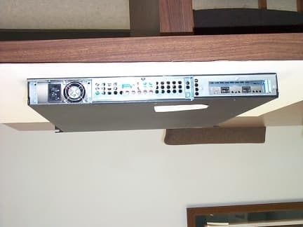
Click to zoom
Application Details
- Equipment Class
- JBC - Part 15 Class B Computing Device/Personal Computer
- Date of Grant
- Dec 21, 2000
- Application Purpose
- Original Equipment
- Date of Application
- Oct 26, 2000
- Equipment Note
- The Tricord Server Appliance
- Company
- Tricord Systems Inc
- Country
- United States
Documents & Files
Document Text
Text extracted from the exhibit documents filed with the FCC. Open a document above to read the original.
Users Manual
Tricord TBD Quick Start Guide Contents: Tricord TBD Standard AC Power Cord (2) 10/100 Ethernet Cable Rack Mounting Brackets and Rubber Feet Installation/IP CD-Rom What You Will Need: Windows 95, 98, 2000 or NT Internet Explorer 5.5 CD-Rom Internet Access (for manual) Optional: 19” Mounting Rack (For up to 16 Nodes) Rack Mounting Brackets Compatible Drawer Slide Kits One Time Set-Up: You will need the following: • IP Address, Main & Back Channel • Subnet Number • Gateway Number • Mail Server Address • Email Address (for alerts) • DNS/Wins IP Address Insert the Installation/IP CD-Rom. The IP Setup launches automatically and searches your local network for any new, unassigned Tricord TBDs. Choose a node. Click on the “Configure” button. The configuration dialog box appears. Follow the easy to use configuration pro- cedures until all of your nodes are config- ured, then exit the IP Set up. The “Storage Manager Setup” will launch. Use the Storage Manager Setup screens to set passwords, alerts, time/date stamp and connect to your network. When you have completed the setup, click on the “Finish” button. The “Storage Manager” will launch. Read and understand the user manual before using this unit. Failure to follow directions could result in a loss of data. Manual is available at www.tricord.com CAUTION Follow the intuitive Storage Manager to set up and man- age nodes, shares, clusters and hot spares. Congratulations, you’re done! Not Released,Tricord cofidential10-19-00, Form#810001-00-Rev A. Tricord TBD Back Panel Interface Matrix Standard 3-prong AC Power Cord Connection 10/100 Ethernet Cable Port (orange) 10/100 Ethernet Cable Port (blue) IP Setup Storage Manager Setup Storage Manager Administration: Create Cluster Alerts Network Date/Time Upgrade Enterprise: Cluster Edit Nodes Status/Security Logs Shares/Permissions Maintenance Port Connect Tricord TBD Standard 3-Prong AC Power Cord Power Source 115VAC to Connect to 10/100 Tricord TBD (2)10/100 Ethernet Cables (Orange and Blue) Switch Connect to Connect to Tricord TBD Front Panel Typical Configuration Mounted Green Indicator = "Power On" Rack Yellow Indicator = "Activity" Switch Three Node Rack User(s)
Block Diagram
Tricord Model: The Tricord Server Appliance Block Diagram CPU Mother Board Ethernet Board DC Power Supply Hard Drive Storage 120 VAC, 60 Hz Cable Connection to a LAN system
Cover Letter(s)
1100 Falcon Ave.Tele:320-864-4444 Glencoe, MN 55336Fax: 320-864-6611 “Your Agent to Product Certifications and Licenses Throughout the World” To:FCCOctober 27, 2000 From: Duane R. Bagdons Subject: Electrical Schematic The mother board that is used in the Tricord Server Appliance is made by ASUS, Model: CUBX rev 1.02. No changes have been made to the manufacturers design. We have tried to obtain an electrical schematic from the manufacturer to file with this report but so far have been unsuccessful. INTERNATIONAL CERTIFICATION SERVICES INC.
External Photos
Tricord Systems, Inc. Model: The Tricord Server Appliance External Photos Front View Tricord Systems, Inc. Model: The Tricord Server Appliance External Photos Rear View
ID Label/Location Info
Tricord Systems, Inc. Model: The Tricord Server Appliance FCC ID
ID Label/Location Info
Tricord Systems, Inc. Model: The Tricord Server Appliance FCC ID Label location FCC ID label location Top Bottom
Internal Photos
Tricord Systems, Inc. Model: The Tricord Server Appliance Internal Photos ENET board CPU Mother Board Power Supply Hard Drives Tricord Systems, Inc. Model: The Tricord Server Appliance Internal Photos Internal Kalex ETHERNET board
Operational Description
(i) The Tricord TBD BETA 2 Manual: Not for Release. This Beta Manual is a Work-In-Progress and may contain errors. Please use as a reference ONLY. (ii) (iii) Tricord ® TBD Manual 810002-00 Revision A Beta 2 (iv) Data contained in this manual is based on the most current information and software revision level that is available at the time of printing. In accordance with Tricord’s policy of consistent product improvement, this manual is subject to change with out notice. You can obtain manual updates at www.tricod.com. Be sure to cross reference the manual revision level with the software revision level in the “Revision Log” in the Appendix and make certain that you are using a manual that is consistent with the software that you are using on the Tricord TBD. The Tricord TBD is to be used only for its intended and stated purpose. Any other use of the TBD constitutes a misuse of the product, voids the Tricord warranty and releases Tricord from liability related to misuse. The Tricord TBD is a sealed unit. Breaching the seal voids the Tricord war- ranty. Tricord ® and the Tricord logo are trademarks of Tricord. (anyother brand that we mention®)is a trademark (copyright etc) of (whoever) Technical Support If you have question or comments concerning the operation of the Tricord TBD , a member of our Technical Support Staff will be happy to assist you. Ask for Technical Support at: 763.551.6359 or 1.800.TRICORD. Tricord ® 2905 Northwest Blvd., Suite 20 Plymouth, MN 55441 © 2000 Tricord. All rights reserved (v) This is a sealed unit and should not be opened under any circumstance. Opening the unit can put you at risk of electrocution. Opening the unit can damage the unit and will void the warranty. CAUTION Read and understand the user manual before using this unit. Failure to follow directions could result in a loss of data. WARNING r e a d a n d u n d e r s ta n d t h e m a n u a l r e a d a n d u n d e r s t a n d t h e m a n u a l r e a d a n d u n d e r s ta n d t h e m a n u a l r e a d a n d u n d e r s t a n d t h e m a n u a l r e a d a n d u n d e r s t a n d t h e m a n u a l r e a d a n d u n d e r s t a n d t h e m a n u a l r e a d a n d u n d e r s t a n d t h e m a n u a l r e a d a n d u n d e r s ta n d t h e m a n u a l r e a d a n d u n d e r s t a n d t h e m a n u a l r e a d a n d u n d e r s ta n d th e m a n u a l r e a d a n d u n d e r s t a n d th e m a n u a l r e a d a n d u n d e r s ta n d t h e m a n u a l (vi) (vii) Table of Contents Introduction The Tricord ......................................................................................................................... 11 Introducing The Tricord TBD .............................................................................................. 12 Hardware installation and Connections Tricord TBD Cable Connections........................................................................................ 15 Tricord TBD Front Panel LEDs .......................................................................................... 16 Rack Mounting Instructions ................................................................................................ 17 What is... Nodes, clusters, Shares and Hot Spare Nodes.................................................................. 21 The Enterprise Tree............................................................................................................22 The Matrix .......................................................................................................................... 23 Tricord Software Worksheet Tricord Software Worksheet ............................................................................................... 27 IP Setup Tricord TBD One Time IP Setu p......................................................................................... 31 Storage Manager Setup Tricord TBD Storage Manager Setu p................................................................................. 39 Storage Manager Tricord TBD Storage Manager ........................................................................................... 47 Administration..................................................................................................................... 48 The Enterprise Tree............................................................................................................55 When A Node Fails When A Node Fails............................................................................................................. 73 Healing a Node healing A Node ................................................................................................................... 77 Mapping A Drive Windows 2000....................................................................................................................81 Windows 98........................................................................................................................ 82 Window 95.......................................................................................................................... 83 Windows NT ....................................................................................................................... 84 (viii) Acronyms Acronyms ........................................................................................................................... 85 Glossary Glossary ............................................................................................................................. 90 Appendix Appendix A - Tricord TBD Specifications ............................................................................ 95 Appendix B - Quick Reference Table ................................................................................. 97 Appendix C - Features and Functions Table ...................................................................... 98 Appendix D - Troubleshooting ................................................…
Text truncated - open the document above for the full version.
Test Report
TEST REPORT #211000 STANDARD: FCC PART 15 SUBPART B--UNINTENTIONAL RADIATORS SECTION 15.109 RADIATION EMISSION LIMITS EQUIPMENT TESTED: TRICORD SYSTEMS, INC. MODEL: THE TRICORD SERVER APPLIANCE TEST DATE: 21 OCTOBER 2000 INTERNATIONAL CERTIFICATION SERVICES, INC. 1100 Falcon Avenue Glencoe, MN 55336 Tele: 320-864-4444 Fax: 320-864-6611 Prepared for: Test agent: Test location: Prepared by: . Tricord Systems, Inc. 2905 Northwest Blvd, Suite 20 Plymouth, MN 55441-2644 International Certification Services, Inc. 1100 Falcon Avenue Glencoe, MN 55336 Tele: 320-864-4444 Fax: 320-864-6611 International Certification Services, Inc. 1100 Falcon Avenue Glencoe, MN 55336 Tele: 320-864-4444 Fax: 320-864-6611 International Certification Services, Inc. 1100 Falcon Avenue Glencoe, MN 55336 International Certification Services represents to the client that testing is done in accordance with standard procedures applicable and that reported test results are accurate within generally accepted commercial ranges of accuracy. This report only applies to the specific samples tested under stated test conditions. It is the manufacturer’s responsibility to assure that additional production units of this model are manufactured with identical electrical and mechanical components. International Certification Services shall have no liability for any deductions, inferences or generalizations drawn by the client or others from this report. This report is the confidential property of the client. As a mutual protection to our clients, the public and ourselves, extracts from the test report shall not be reproduced except in full without our written approval. 1.0 TEST SUMMARY TEST REPORT: #211000 COMPANY: AGENT: International Certification Services, Inc. PHONE: 320-864-4444 TEST DATE: EQUIPMENT UNDER TEST: GENERAL TEST SUMMARY: VERIFICATION / CERTIFICATION STATUS: MODIFICATIONS NECESSARY: TESTED BYWRITTEN BY Steve WendlandtDuane R. Bagdons Tricord Systems, Inc. 21 October, 2000 High Capacity Storage Appliance System Model: The Tricord Server Appliance The testing was performed at International Certification Services, Inc. at 1100 Falcon Ave, Glencoe, MN 55336 The Tricord Systems, Inc., Model: The Tricord Server Appliance system was found to be in compliance with the FCC Part 15 Subpart B, Section 15.109 requirements. None Applicable Standards 47 CFR Ch.1 (10-1-98 Edition) FCC Part 15Radio Frequency Devices Subpart BUnintentional Radiators Section 15.109Radiated Emission Limits 2.1Referenced Standards ANSI C63.4-1992Methods of Measurement of Radio-Noise Emissions from Low- Voltage Electrical and Electronic Equipment in the Range of 9 Khz to 40 Ghz. 2.2 Equipment Units Tested The Tricord Server Appliance is a specialized computer system that uses many standard computer components packaged in a rack mount chassis. The Tricord software running on the Linux operating system provides file storage over an Ethernet interface with browser based management. During testing a HUB was connected to the input and output LAN cables so data could be passed back and forth during the testing. 2.3 Equipment and Cable Configuration See photos of the EUT pc board and schematic and test configuration setup in Attachment A 2.4 List of Test Equipment Measurement cable losses, and antenna correction factors are included in the data sheets. Quasi-Peak detection methods were used in the measurements. The Resolution BW was set at 100 Khz and the Video BW was set at 300 Khz. 2.5 Units of Measurement. All measurements were taken in dBuV/m with the antenna located at 3 meters distance from the EUT. Frequency measurements are recorded in Mhz Test Equipment Spectrum Analyzer Preamp Biconical Antenna Log Periodic Antenna (200-1000 MHz) Horn Antenna (1-10 Ghz) Model Hewlett-Packard 8566B MiniCircuits ZKL-2R7 AH Systems Model SAS- 200/540 EMCO 3146 EMCO 3115 S/N 2421A00458 N/A 328 9111-3280 2334 Calibration Date 09/24/00 09/24/00 09/24/00 09/24/00 09/24/00 2.6 Location of Test Site The open area test site (OATS) measurement facility used to collect the data was International Certification Services, Inc. at 1100 Falcon Ave in Glencoe, MN 55336. This site has been certified to be in spec of the normalized site attenuation per ANSI C63.4-1992 . See letter of compliance from FCC dated July 23, 1998. (FCC 31040/SIT 1300F2) 2.7 Measurement Procedures The Tricord Server Appliance was placed on a non conducting table with cables plugged into all external connectors. A peripheral HUB device was connected to the input and output LAN connectors to keep data flowing during the testing to the HUB. Data was turned around in the HUB and sent back to the EUT. This program was running continually during the testing. The ASUS CPU board was tested with both a 700 Mhz processor chip (P/N: Intel 700/256/100/1.65V P/N: 3018A253-0749), and a 800 Mhz processor chip (P/N: Intel 800/256/100/1.65V P/N: 3028A546-0556. The data presented is the maximum of both processors. The receiving antenna was placed at a distance of 3 meters from the EUT. The EUT was set on an insulating table in the OATS site and rotated through 360 degrees to determine the worst case EUT orientation. The antenna was positioned vertical and horizontal to determine which antenna polarity orientation was worst case. Then certification data was recorded at all the frequencies from the fundamental to the 10 th harmonic at an antenna height variation of from 1-4 meters. 2.8Reporting Measurement Data See data sheets and plots in Attachment B. 2.9Radiated Emissions Data The frequency and amplitude of the tuned frequency of the EUT along with the frequencies and amplitudes of the harmonics are reported in the data sheets in Attachment B. This information is plotted against the limit of section 15.109 of FCC Part 15 subpart B. The polarization of the antenna for each measurement is also recorded. The Final Level, expressed in dBuV/m, is arrived at by taking the reading from the spectrum analyzer (Level dBuV) and adding the an…
Text truncated - open the document above for the full version.
Test Report
1100 Falcon Ave.Tele:320-864-4444 Glencoe, MN 55336Fax: 320-864-6611 “Your Agent to Product Certifications and Licenses Throughout the World” To:Dianne PooleDecember 9, 2000 From: Duane R. Bagdons Correspondence Ref No. 16884 Confirmation No. EA99145 Client: Tricord Systems, Inc. Dear Dianne, I have secured another system from the client to test and here are the photos and test results. Radiated Test data Freq (Mhz) (dBuV)Cable Corr Fac Ant Corr Fac Preamp Gain Corr Data (dBuV) FCC Class B Limits Margin 49.1247.710.2881.56372237.55240-2.448 66.8446.29.83681.879222235.91640-4.084 76.5644.89.66882.05262234.521440-5.4786 77.1944.39.65622.063842234.0240-5.98 457.90540.916.85814.709042240.467146.02-5.5529 567.91537.618.77925.484172239.863346.02-6.1567 601.36537.318.95.644532239.844546.02-6.1755 701.61534.421.48395.729352239.613246.02-6.4068 801.81534.121.46.841562240.341646.02-5.6784 915.81432.523.14197.091772240.733646.02-5.2864 Conducted Test data: Freq (Mhz) dBuVCONDLISN Corr Fac Cable Corr Fac EM7600 Corr Fac Corr Data (dBuV) FCC Class B Limits Margin 0.4533.2 Line L-0.480.21042.9248-5.08 0.457532.5 Line N-0.480.1251042.14548-5.855 0.61730 Line L-0.480.131039.6548-8.35 0.617530.2 Line N-0.480.1251039.84548-8.155 7.68728.3 Line L-0.480.41038.2248-9.78 8.582529.3 Line N-0.480.41039.2248-8.78 8.8331.8 Line N-0.480.471041.7948-6.21 9.242531.3 Line N-0.480.41041.2248-6.78 10.949529.7 Line L-0.480.41039.6248-8.38 15.11529.2 Line N-0.480.61039.3248-8.68 INTERNATIONAL CERTIFICATION SERVICES INC. International Certification Services, Inc. [email protected] Radiated Emissions Test configuration Conducted Emissions Test Configuration
Test Setup Photos
Tricord Systems, Inc. Model: The Tricord Server Appliance Test Set Up photos Radiated Emissions Tricord Systems, Inc. Model: The Tricord Server Appliance Test Set Up photos Conducted Emissions
Contact Information
Applicant
Philip Savoie
Test Firm
International Certification Services Inc.Duane Bagdons
Technical Specifications
| # | Rule Parts | Frequency Range | Power Output |
|---|---|---|---|
| 1 | 15B | - | - |