INC-66121Wireless Headphone Emitter
Zhejiang Focus-On Import and Export Co., Ltd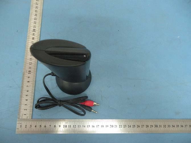
Click to zoom
Application Details
- Equipment Class
- DXX - Part 15 Low Power Communication Device Transmitter
- Date of Grant
- May 29, 2012
- Application Purpose
- Original Equipment
- Date of Application
- May 29, 2012
- Equipment Note
- Wireless Headphone Emitter
- Frequency Range
- 88.10000000 - 88.10000000
- Country
- China
Documents & Files
Document Text
Text extracted from the exhibit documents filed with the FCC. Open a document above to read the original.
Users Manual
Insert two AAA batteries into the battery compartmentaccording to the + and- polarity. tune the power On/Off of the receiver, then the receiver indicator will brighten. Insert two AAA batteries into the battery compartment according to the + and polarity (3.0V DC).Insertaudio plug of the emitter into AUDIO-OUT socket of audio source (such as TV set audio device PCDVD playerCD playerMP3 playeretc.). Please see Fig.1, Fig.2, Fig.3, Fig.4 ( Note: locate the emitter at a highposition in order to achieve bestreception effect) - 、 、、、、 、 () () 1Please see Fig.1, Insert the emitter audio cable into the AUDIO-OUT socket of theelectronic device or headphone socket, and move the function switch of the emitter to the“ON” position, then the emitter indicator shine. 2Built in the battery on the emitter and the receiver, draw the function switch () () () 1Connect the emitter audio cable to the adaptor cable (optional) (see Fig.2), and insert the other end of the adaptor cable into the audio out socket of the PC, then insert one end of the audio cable (optional) into the microphone socket (MIC) on theemitter, and insert the other end into the microphone in socket of the PC. 2Turn on the power switch of the emitter, then the indicator brighten, putthe out-built MIC forward yourself and keep away with the distance of 0.5M. 3open your chat tool and tune the power On/Off button , then the indicator of the headphone brighten. Adjust the volume to the suitable position, then headphone can receive the sound via the SKYPE/MSN/QQ from your friends in the other end. (see Fig.3) The receiver can be used separately as an FM radio. First draw the function switchto the “FM” position, and then press the “RESET” once, then press the “SCAN”key in turn to search a higher range and lock one radio channel; when the highest range is reached, press “RESET” key, and the frequency returns to the lowest range. Press “SCAN” key again, and the receiver will search the radio channels from thelow range again. Insert one end of the audio cable (optional) into the audio socket of the receiver (see Fig.4), and insert the other end into the headphone socket of the electronic devices, such as MP3 playerVCD playerDVD player etc., and then the unit can be used as a wired headphone. 、、、 Parts Package include Emitter Receiver(Headphone) Instruction Manual Audio cable Audio Transform cable 1 1 1 1 1 Installation Operation Wireless net audio chat Listen to the radio Wired Headphone (without batteries) Wireless headphone Installing the emitter: Installing the receiver: to the “WIRELESS” position, the receiver indicator brighten. Put the volume control to asuitable position, then adjust the tiny modulation on the emitter till getting abest effect (largest sound and clearest). Technical Specifications Emitter Emission frequency: 88.1MHz Modulation mode: FM Emission distance: 30M (with no interference) Power supply: 2xAAA batteries . Frequency range: 88.1MHz for wireless headphone and 87-108MHz for FM radio. ReceptionMode: FM Distortion: PowerSupply2xAAAbatteries 2% : Receiver(headphone) Notes To achieve best reception spread out emitter audio cable of the emitter or locate the emitter at a higher position.(the emitter audio cable can also be used as antenna). If the sound is distorted or too strong, adjust the volume of the signal source (TV setVCDplayer DVD playerPCMP3 walkman etc.) To a lower level, and reception performance may be improved. 、、、、、、 Replace the batteries if you are having the following problems The emitter indicator becomes dim. The receiver reception is poor. The volume becomes weak and the sound is distored. 1) 2) 3) AReceiver BEmitter 1.Battery compartment cover 2.Volume control and power button (ON/OFF) 3.Scan key(SCAN) 4.Reset key(RESET) 5.Power indicator 6 .Audio socket 7Power indicator (Front ) 8.Power and function switch 9.Microphone socket (MIC) 10.Vacancy 11.Microphone (MIC) 12.Audio cable of emitter 13.Battery compartment cover (bottom) . MIC MIC Wireless monitoring (1) Turn on the emitter by tuning power switch . Then the emitter indicator brighten up. (2)Turn on the receiver by tuning Volume control button. Then the receiver indicator brighten up. (3) Place the emitter with the wards. Press RESET button, then press SCAN button to SCAN sound from wards automatically. changes or modifications not expressly approved by the party responsible for compliance could void the user's authority to operate the equipment. NOTE: This equipment has been tested and found to comply with the limits for a Class B digital device, pursuant to Part 15 of the FCC Rules. These limits are designed to provide reasonable protection against harmful interference in a residential installation. This equipment generates, uses and can radiate radio frequency energy and, if not installed and used in accordance with the instructions, may cause harmful interference to radio communications. However, there is no guarantee that interference will not occur in a particular installation. If this equipment does cause harmful interference to radio or television reception, which can be determined by turning the equipment off and on, the user is encouraged to try to correct the interference by one or more of the following measures: -- Reorient or relocate the receiving antenna. -- Increase the separation between the equipment and receiver. -- Connect the equipment into an outlet on a circuit different from that to which the receiver is connected. -- Consult the dealer or an experienced radio/TV technician for help. FCC ID:INC-66121 This device complies with Part 15 of the FCC Rules. Operation is subject to the following two conditions: (1) this device may not cause harmful interference, and (2) this device must accept any interference received, including interference that may cause undesired operation.
Users Manual
Insert two AAA batteries into the battery compartmentaccording to the + and- polarity. tune the power On/Off of the receiver, then the receiver indicator will brighten. Insert two AAA batteries into the battery compartment according to the + and polarity (3.0V DC).Insertaudio plug of the emitter into AUDIO-OUT socket of audio source (such as TV set audio device PCDVD playerCD playerMP3 playeretc.). Please see Fig.1, Fig.2, Fig.3, Fig.4 ( Note: locate the emitter at a highposition in order to achieve bestreception effect) - 、 、、、、 、 () () 1Please see Fig.1, Insert the emitter audio cable into the AUDIO-OUT socket of theelectronic device or headphone socket, and move the function switch of the emitter to the“ON” position, then the emitter indicator shine. 2Built in the battery on the emitter and the receiver, draw the function switch () () () 1Connect the emitter audio cable to the adaptor cable (optional) (see Fig.2), and insert the other end of the adaptor cable into the audio out socket of the PC, then insert one end of the audio cable (optional) into the microphone socket (MIC) on theemitter, and insert the other end into the microphone in socket of the PC. 2Turn on the power switch of the emitter, then the indicator brighten, putthe out-built MIC forward yourself and keep away with the distance of 0.5M. 3open your chat tool and tune the power On/Off button , then the indicator of the headphone brighten. Adjust the volume to the suitable position, then headphone can receive the sound via the SKYPE/MSN/QQ from your friends in the other end. (see Fig.3) The receiver can be used separately as an FM radio. First draw the function switchto the “FM” position, and then press the “RESET” once, then press the “SCAN”key in turn to search a higher range and lock one radio channel; when the highest range is reached, press “RESET” key, and the frequency returns to the lowest range. Press “SCAN” key again, and the receiver will search the radio channels from thelow range again. Insert one end of the audio cable (optional) into the audio socket of the receiver (see Fig.4), and insert the other end into the headphone socket of the electronic devices, such as MP3 playerVCD playerDVD player etc., and then the unit can be used as a wired headphone. 、、、 Parts Package include Emitter Receiver(Headphone) Instruction Manual Audio cable Audio Transform cable 1 1 1 1 1 Installation Operation Wireless net audio chat Listen to the radio Wired Headphone (without batteries) Wireless headphone Installing the emitter: Installing the receiver: to the “WIRELESS” position, the receiver indicator brighten. Put the volume control to asuitable position, then adjust the tiny modulation on the emitter till getting abest effect (largest sound and clearest). Technical Specifications Emitter Emission frequency: 88.1MHz Modulation mode: FM Emission distance: 30M (with no interference) Power supply: 2xAAA batteries . Frequency range: 88.1MHz for wireless headphone and 87-108MHz for FM radio. ReceptionMode: FM Distortion: PowerSupply2xAAAbatteries 2% : Receiver(headphone) Notes To achieve best reception spread out emitter audio cable of the emitter or locate the emitter at a higher position.(the emitter audio cable can also be used as antenna). If the sound is distorted or too strong, adjust the volume of the signal source (TV setVCDplayer DVD playerPCMP3 walkman etc.) To a lower level, and reception performance may be improved. 、、、、、、 Replace the batteries if you are having the following problems The emitter indicator becomes dim. The receiver reception is poor. The volume becomes weak and the sound is distored. 1) 2) 3) AReceiver BEmitter 1.Battery compartment cover 2.Volume control and power button (ON/OFF) 3.Scan key(SCAN) 4.Reset key(RESET) 5.Power indicator 6 .Audio socket 7Power indicator (Front ) 8.Power and function switch 9.Microphone socket (MIC) 10.Vacancy 11.Microphone (MIC) 12.Audio cable of emitter 13.Battery compartment cover (bottom) . MIC MIC Wireless monitoring (1) Turn on the emitter by tuning power switch . Then the emitter indicator brighten up. (2)Turn on the receiver by tuning Volume control button. Then the receiver indicator brighten up. (3) Place the emitter with the wards. Press RESET button, then press SCAN button to SCAN sound from wards automatically. changes or modifications not expressly approved by the party responsible for compliance could void the user's authority to operate the equipment. NOTE: This equipment has been tested and found to comply with the limits for a Class B digital device, pursuant to Part 15 of the FCC Rules. These limits are designed to provide reasonable protection against harmful interference in a residential installation. This equipment generates, uses and can radiate radio frequency energy and, if not installed and used in accordance with the instructions, may cause harmful interference to radio communications. However, there is no guarantee that interference will not occur in a particular installation. If this equipment does cause harmful interference to radio or television reception, which can be determined by turning the equipment off and on, the user is encouraged to try to correct the interference by one or more of the following measures: -- Reorient or relocate the receiving antenna. -- Increase the separation between the equipment and receiver. -- Connect the equipment into an outlet on a circuit different from that to which the receiver is connected. -- Consult the dealer or an experienced radio/TV technician for help. FCC ID:INC-66121 This device complies with Part 15 of the FCC Rules. Operation is subject to the following two conditions: (1) this device may not cause harmful interference, and (2) this device must accept any interference received, including interference that may cause undesired operation.
Cover Letter(s)
Zhejiang Focus-On Import and Export Co., Ltd PHOENIX TEST-LAB GmbH Product Certification Königswinkel 10 D 32825 Blomberg Date: 19.05.2012 Authority to Act as an Agent We declare that the following representative (agent) Name Mark Zhu Position Manager Company Name Shenzhen Certification Technology Service Co., Ltd. Address 2F, Building B, East Area of Nanchang Second Industrial Zone, Gushu 2 nd Road, Bao’an District, Shenzhen 518126, P.R. China Tel / Fax 0755-86375541/0755-26736857 Email [email protected] to act on our behalf on all matters concerning the application and documents submitted to PHOENIX TEST-LAB for product certification below Product Name RF wireless headphone Model Name 66121 Brand Name We also authorize BZT – TCP Certification GmbH, Ms.Wanida Patthanavoj (address: Hermann - Loens - Weg 6, 15859 Storkow b. Berlin Germany) to process the application. Yours sincerely, Signatory Name tongbingtuan Position manager Company Name Zhejiang Focus-On Import and Export Co., Ltd Address 11F, Binhai Building, 480 Jiangnan Dadao, Binjiang District, Hangzhou, China Tel +86-571-86688701 Fax + 86-571-81603555 Email [email protected] In case of FCC, we certify that we are not subject to a denial of Federal benefits, that include FCC benefits, pursuant to Section 5301 of the Anti-Drug Abuse Act of 1988, 21 U.S.C. §862 because of a conviction for possession or distribution of a controlled substance.
Cover Letter(s)
Zhejiang Focus-On Import and Export Co., Ltd Federal Communications Commission Equipment Authorization Branch 7435 Oakland Mills Road Columbia, MD 21046 Request for Confidentiality Company name: Zhejiang Focus-On Import and Export Co., Ltd FCC ID : INC-66121 FCC Part 15 Certification Gentlemen, Pursuant to 47 CFR 0.457(d)(1)(ii) and 0.459 we hereby requests permanent confidentiality of the following documents for the subject application: Exhibit Type Description ☒ Schematics All circuitry of devices and component values ☒ Block Diagrams Details of device showing the frequency of all oscillators ☒ Operational Description Description of the circuit functions Note: Exhibit types that are commonly held confidential are: (1) Schematics, (2) Block Diagrams, (3) Bill Of Materials, (4) Operational Descriptions. Any exhibit NOT granted confidentiality is viewable on the FCC website as soon as a grant is issued. These documents contain detailed system and equipment description and related information about the product which we considers to be proprietary, confidential and a custom design and otherwise would not release to the general public. Since the design is a basis from which future technological products will evolve, we consider that this information would be of benefit to its competitors and that the disclosure of the information in these documents would give competitors an unfair advantage in the market. Yours sincerely, Signatory Name tongbingtuan Position manager Company Name Zhejiang Focus-On Import and Export Co., Ltd Address 11F, Binhai Building, 480 Jiangnan Dadao, Binjiang District, Hangzhou, China Tel +86-571-86688701 Fax +86-571-81603555 Email [email protected]
Cover Letter(s)
Zhejiang Focus-On Import and Export Co., Ltd PHOENIX TEST-LAB GmbH Product Certification Königswinkel 10 D 32825 Blomberg Date: 19.05.2012 Authority to Act as an Agent We declare that the following representative (agent) Name Mark Zhu Position Manager Company Name Shenzhen Certification Technology Service Co., Ltd. Address 2F, Building B, East Area of Nanchang Second Industrial Zone, Gushu 2 nd Road, Bao’an District, Shenzhen 518126, P.R. China Tel / Fax 0755-86375541/0755-26736857 Email [email protected] to act on our behalf on all matters concerning the application and documents submitted to PHOENIX TEST-LAB for product certification below Product Name RF wireless headphone Model Name 66121 Brand Name We also authorize BZT – TCP Certification GmbH, Ms.Wanida Patthanavoj (address: Hermann - Loens - Weg 6, 15859 Storkow b. Berlin Germany) to process the application. Yours sincerely, Signatory Name tongbingtuan Position manager Company Name Zhejiang Focus-On Import and Export Co., Ltd Address 11F, Binhai Building, 480 Jiangnan Dadao, Binjiang District, Hangzhou, China Tel +86-571-86688701 Fax + 86-571-81603555 Email [email protected] In case of FCC, we certify that we are not subject to a denial of Federal benefits, that include FCC benefits, pursuant to Section 5301 of the Anti-Drug Abuse Act of 1988, 21 U.S.C. §862 because of a conviction for possession or distribution of a controlled substance.
Cover Letter(s)
Zhejiang Focus-On Import and Export Co., Ltd Federal Communications Commission Equipment Authorization Branch 7435 Oakland Mills Road Columbia, MD 21046 Request for Confidentiality Company name: Zhejiang Focus-On Import and Export Co., Ltd FCC ID : INC-66121 FCC Part 15 Certification Gentlemen, Pursuant to 47 CFR 0.457(d)(1)(ii) and 0.459 we hereby requests permanent confidentiality of the following documents for the subject application: Exhibit Type Description ☒ Schematics All circuitry of devices and component values ☒ Block Diagrams Details of device showing the frequency of all oscillators ☒ Operational Description Description of the circuit functions Note: Exhibit types that are commonly held confidential are: (1) Schematics, (2) Block Diagrams, (3) Bill Of Materials, (4) Operational Descriptions. Any exhibit NOT granted confidentiality is viewable on the FCC website as soon as a grant is issued. These documents contain detailed system and equipment description and related information about the product which we considers to be proprietary, confidential and a custom design and otherwise would not release to the general public. Since the design is a basis from which future technological products will evolve, we consider that this information would be of benefit to its competitors and that the disclosure of the information in these documents would give competitors an unfair advantage in the market. Yours sincerely, Signatory Name tongbingtuan Position manager Company Name Zhejiang Focus-On Import and Export Co., Ltd Address 11F, Binhai Building, 480 Jiangnan Dadao, Binjiang District, Hangzhou, China Tel +86-571-86688701 Fax +86-571-81603555 Email [email protected]
External Photos
To p Vi e w Bottom View Front View Left View Rear View Right View
External Photos
To p Vi e w Bottom View Front View Left View Rear View Right View
ID Label/Location Info
Label Location 37mm 12mm Manufacturer : Zhejiang Focus-On Import and Export Co., Ltd Model Number: 66121 F CC ID: INC-66121 This devi ce complies with Part 15 of the FCC Rules. Operation is subject to the following two conditions: (1) this device may not cause harmful interference, and (2) this device must accept any interference received, inclu ding interference that may cause undesired operation.
ID Label/Location Info
Label Location 37mm 12mm Manufacturer : Zhejiang Focus-On Import and Export Co., Ltd Model Number: 66121 F CC ID: INC-66121 This devi ce complies with Part 15 of the FCC Rules. Operation is subject to the following two conditions: (1) this device may not cause harmful interference, and (2) this device must accept any interference received, inclu ding interference that may cause undesired operation.
Internal Photos
To p Vi e w To p Vi e w ANTENNA
Internal Photos
To p Vi e w To p Vi e w ANTENNA
Test Report
Shenzhen Certification Technology Service Co., Ltd 2F, Building B, East Area of Nanchang Second Industrial Zone, Gushu 2nd Road, Bao'an District, Shenzhen 518126, P.R. China. FCC ID: INC-66121 Page 1 of 24 TEST REPORT FCC ID: INC-66121 Applicant : Zhejiang Focus-On Import and Export Co., Ltd Address : 11F, Binhai Building, 480 Jiangnan Dadao, Binjiang District, Hangzhou, China Equipment under Test (EUT): Name : RF wireless headphone Model : 66121 Standards : FCC Part15.239 Report No. : STE120516574 Date of Test : May 18-20, 2012 Date of Issue : May 21, 2012 Test Result : PASS * * In the configuration tested, the EUT complied with the standards specified above Authorized Signature (Mark Zhu) General Manager The manufacture should ensure that all the products in series production are in conformity with the product sample detailed in this report. If the product in this report is used in any configuration other than that detailed in the report, the manufacturer must ensure the new system complies with all relevant standards. Any mention of Shenzhen Certification Technology Service Co., Ltd. Or test done by Shenzhen Certification Technology Service Co., Ltd. Approvals in connection with, distribution or use of the product described in this report must be approved by Shenzhen Certification Technology Service Co., Ltd. Approvals in writing. Report No.: 120516574 FCC ID: INC-66121 Page 2 of 24 TABLE OF CONTENT Description Page 1 General Information -------------------------------------------------------------------- 3 1.1 Description of Device (EUT)------------------------------------------------------------------ 3 1.2 Description of Test Facility-------------------------------------------------------------------- 4 2 Test Equipment List -------------------------------------------------------------------- 4 3 Test Procedure -------------------------------------------------------------------------- 5 4 Summary of Measurement ----------------------------------------------------------- 6 5 POWER LINE CONDUCTED EMISSION ---------------------------------------- 7 5.1 Conducted Emission Limits(15.209 ) -------------------------------------------------------- 7 5.3 Test Setup------------------------------------------------------------------------------------------ 7 5.3 Test Procedure------------------------------------------------------------------------------------ 8 5.4 Test Resluts---------------------------------------------------------------------------------------- 8 6 Radiated Emission Test --------------------------------------------------------------- 9 6.1 Radiated Emission Limits(15.209&239)---------------------------------------------------- 9 6.2 Test Setup for Emission measurement---------------------------------------------------- 10 6.3 Test Procedure ---------------------------------------------------------------------------------- 11 6.4 Test Condition ----------------------------------------------------------------------------------- 12 7 Bandwidth Test -------------------------------------------------------------------------17 7.1 Limit for Bandwidth ----------------------------------------------------------------------------- 17 7.2 Method of measurement ---------------------------------------------------------------------- 17 7.3 Test Setup----------------------------------------------------------------------------------------- 17 7.4 Test Results--------------------------------------------------------------------------------------- 17 8 Band Edge Test ------------------------------------------------------------------------18 8.1 Test Limit ----------------------------------------------------------------------------------------- 18 8.2 Test Procedure --------------------------------------------------------------------------------- 18 8.3 Test Results ------------------------------------------------------------------------------------- 18 9 Antenna Requirement ----------------------------------------------------------------19 9.1 Standard requirement -------------------------------------------------------------------------- 19 9.2 Result ---------------------------------------------------------------------------------------------- 19 10 Photographs of Test Setup ----------------------------------------------------------20 11 Photographs of EUT ------------------------------------------------------------------21 Report No.: 120516574 FCC ID: INC-66121 Page 3 of 24 1 General Information 1.1 Description of Device (EUT) Trade Name : N/A EUT : RF wireless headphone Model No. : 66121 : Type of Antenna : Integral Antenna, Max Gain 0dBi. Operation Frequency : 88.1 Modulation type FM Power Supply : DC 3V Supply by Battery Applicant : Zhejiang Focus-On Import and Export Co., Ltd Address : 11F, Binhai Building, 480 Jiangnan Dadao, Binjiang District, Hangzhou, China Manufacturer : Zhejiang Focus-On Import and Export Co., Ltd Address : 11F, Binhai Building, 480 Jiangnan Dadao, Binjiang District, Hangzhou, China Report No.: 120516574 FCC ID: INC-66121 Page 4 of 24 1.2 Description of Test Facility Shenzhen Certification Technology Service Co., Ltd. 2F, Building B, East Area of Nanchang Second Industrial Zone, Gushu 2nd Road, Bao'an District, Shenzhen 518126, P.R. China FCC Registered No.:197647 1.3 Test Equipment List Equipment Manufacture Model No. Serial No. Last cal. Cal Interval 3m Semi-Anechoic ETS-LINDGREN N/A SEL0017 06/06/20111Year Spectrum analyzer Agilent E4443A MY46185649 06/06/20111Year Receiver R&S ESCI 100492 04/06/20111Year Receiver R&S ESCI 101202 07/01/20121Year Bilog Antenna SCHWARZBECK VULB 9168 VULB9168-4 38 04/06/20111Year L.I.S.N. SCHWARZBECK NSLK8126 8126466 16/06/20111Year Loop Antenna R&S FMZB1516 1516131 04/06/20111Year ETS Horn Antenna ETS 3160 SEL0076 12/08/20111Year Cable Resenberger N/A No.1 04/06/20111Year Cable SCHWARZBECK N/A No.2 04/06/20111Year Cable SCHWARZBECK N/A No.3 04/06/20111Year Pre-amplifier SCHWARZBECK BBV9743 9743-019 06/06/20111Year Pre-amplifier R…
Text truncated - open the document above for the full version.
Test Report
Shenzhen Certification Technology Service Co., Ltd 2F, Building B, East Area of Nanchang Second Industrial Zone, Gushu 2nd Road, Bao'an District, Shenzhen 518126, P.R. China. FCC ID: INC-66121 Page 1 of 24 TEST REPORT FCC ID: INC-66121 Applicant : Zhejiang Focus-On Import and Export Co., Ltd Address : 11F, Binhai Building, 480 Jiangnan Dadao, Binjiang District, Hangzhou, China Equipment under Test (EUT): Name : RF wireless headphone Model : 66121 Standards : FCC Part15.239 Report No. : STE120516574 Date of Test : May 18-20, 2012 Date of Issue : May 21, 2012 Test Result : PASS * * In the configuration tested, the EUT complied with the standards specified above Authorized Signature (Mark Zhu) General Manager The manufacture should ensure that all the products in series production are in conformity with the product sample detailed in this report. If the product in this report is used in any configuration other than that detailed in the report, the manufacturer must ensure the new system complies with all relevant standards. Any mention of Shenzhen Certification Technology Service Co., Ltd. Or test done by Shenzhen Certification Technology Service Co., Ltd. Approvals in connection with, distribution or use of the product described in this report must be approved by Shenzhen Certification Technology Service Co., Ltd. Approvals in writing. Report No.: 120516574 FCC ID: INC-66121 Page 2 of 24 TABLE OF CONTENT Description Page 1 General Information -------------------------------------------------------------------- 3 1.1 Description of Device (EUT)------------------------------------------------------------------ 3 1.2 Description of Test Facility-------------------------------------------------------------------- 4 2 Test Equipment List -------------------------------------------------------------------- 4 3 Test Procedure -------------------------------------------------------------------------- 5 4 Summary of Measurement ----------------------------------------------------------- 6 5 POWER LINE CONDUCTED EMISSION ---------------------------------------- 7 5.1 Conducted Emission Limits(15.209 ) -------------------------------------------------------- 7 5.3 Test Setup------------------------------------------------------------------------------------------ 7 5.3 Test Procedure------------------------------------------------------------------------------------ 8 5.4 Test Resluts---------------------------------------------------------------------------------------- 8 6 Radiated Emission Test --------------------------------------------------------------- 9 6.1 Radiated Emission Limits(15.209&239)---------------------------------------------------- 9 6.2 Test Setup for Emission measurement---------------------------------------------------- 10 6.3 Test Procedure ---------------------------------------------------------------------------------- 11 6.4 Test Condition ----------------------------------------------------------------------------------- 12 7 Bandwidth Test -------------------------------------------------------------------------17 7.1 Limit for Bandwidth ----------------------------------------------------------------------------- 17 7.2 Method of measurement ---------------------------------------------------------------------- 17 7.3 Test Setup----------------------------------------------------------------------------------------- 17 7.4 Test Results--------------------------------------------------------------------------------------- 17 8 Band Edge Test ------------------------------------------------------------------------18 8.1 Test Limit ----------------------------------------------------------------------------------------- 18 8.2 Test Procedure --------------------------------------------------------------------------------- 18 8.3 Test Results ------------------------------------------------------------------------------------- 18 9 Antenna Requirement ----------------------------------------------------------------19 9.1 Standard requirement -------------------------------------------------------------------------- 19 9.2 Result ---------------------------------------------------------------------------------------------- 19 10 Photographs of Test Setup ----------------------------------------------------------20 11 Photographs of EUT ------------------------------------------------------------------21 Report No.: 120516574 FCC ID: INC-66121 Page 3 of 24 1 General Information 1.1 Description of Device (EUT) Trade Name : N/A EUT : RF wireless headphone Model No. : 66121 : Type of Antenna : Integral Antenna, Max Gain 0dBi. Operation Frequency : 88.1 Modulation type FM Power Supply : DC 3V Supply by Battery Applicant : Zhejiang Focus-On Import and Export Co., Ltd Address : 11F, Binhai Building, 480 Jiangnan Dadao, Binjiang District, Hangzhou, China Manufacturer : Zhejiang Focus-On Import and Export Co., Ltd Address : 11F, Binhai Building, 480 Jiangnan Dadao, Binjiang District, Hangzhou, China Report No.: 120516574 FCC ID: INC-66121 Page 4 of 24 1…
Text truncated - open the document above for the full version.
Contact Information
Applicant
tongbing tuan
Test Firm
Shenzhen Certification Technology Service Co., LtdMark Zhu
Technical Specifications
| # | Rule Parts | Frequency Range | Power Output |
|---|---|---|---|
| 1 | 15C | 88.1 MHz - 88.1 MHz | - |