IOU1021S01WLAN PCMCIA Adapter
National Datacomm Corporation
Click to zoom
Application Details
- Equipment Class
- DTS - Digital Transmission System
- Date of Grant
- Feb 26, 2003
- Application Purpose
- Original Equipment
- Date of Application
- Feb 26, 2003
- Equipment Note
- WLAN PCMCIA Adapter
- Frequency Range
- 2412.00000000 - 2472.00000000
- Country
- Taiwan
Documents & Files
Document Text
Text extracted from the exhibit documents filed with the FCC. Open a document above to read the original.
Users Manual
OEM’s manual Version A1 National Datacomm Corporation 4 th Fl., No. 24-2, Industry East Road IV Science-based Industrial Park Hsinchu, Taiwan, R.O.C. Technical Support E-mail: [email protected] NDC World Wide Web http://www.ndclan.com.tw/ CardBus Enhanced Wireless Network Adapter NWH1022 TRADEMARKS NDC and InstantWave are trademarks of National Datacomm Corporation. All other names mentioned in this document are trademarks/registered trademarks of their respective owners. NDC provides this document “as is,” without warranty of any kind, either expressed nor implied, including, but not limited to, the particular purpose for which it is intended. NDC may make improvements and/or changes in this manual or in the product(s) and/or the program(s) described in this manual at any time. This document could include technical inaccuracies or typographical errors. FCC WARNING This equipment has been tested and found to comply with the limits for a Class B Digital device, pursuant to part 15 of the FCC Rules. These limits are designed to provide reasonable protection . This equipment generates, uses, and can radiate radio frequency energy and, if not installed and used in accordance with the instructions, may cause harmful interference to radio communications. However, there is no guarantee that interference will not occur in a particular installation. If this equipment does cause harmful interference to radio or television reception, which can be determined by turning the equipment off and on, the user is encouraged to try to correct the interference by one or more of the following measures: z Reorient or relocate the receiving antenna z Increase the separation between the equipment and receiver z Connect the equipment into an outlet on a circuit different from that to which the receiver is connected z Consult the dealer or an experienced radio/TV technician for help Changes or modifications not expressly approved by the party responsible for compliance could void user's authority to operate the equipment. This device complies with part 15 of the FCC Rules. Operation is subject to the following two conditions: 1. This device may not cause harmful interference, and 2. This device must accept any interference received, including interference that may cause undesired operation FCC RF Radiation Exposure Statement This equipment complies with FCC RF radiation exposure limits set forth for an uncontrolled environment. This equipment should be installed and operated with a minimum distance of 20 centimeters between the radiator and your body. Test CAUTION: This device is not authorized to be integrated and used in PDAs, hand-held devices, laptops, or any portable devices, as separate FCC equipment authorization must be obtained to address RF exposure (SAR) requirements for portable devices into which this module is installed. The device is ONLY approved to be integrated and used in mobiles devices of the type Access Point. ii CardBus Enhanced Wireless Network Adapter CardBus Enhanced Wireless Network Adapter iii Packing List The adapter package should contain the following items: • One InstantWave NWH1022 CardBus enhanced wireless network adapter with integrated antenna • Four floppy disks – one containing drivers, two containing the InstantWave HighRate Utility for the NWH1022, and one containing this user’s guide in PDF format iv CardBus Enhanced Wireless Network Adapter Table of Contents INTRODUCTION .................................................................................................. 1 S YSTEM R EQUIREMENTS ....................................................................................... 1 Hardware ......................................................................................................... 1 Software............................................................................................................ 1 T ERMINOLOGY U SED IN THIS G UIDE ..................................................................... 2 ADAPTER INSTALLATION ............................................................................... 4 LED S .................................................................................................................... 4 DRIVER INSTALLATION/UNINSTALLATION ............................................. 5 I NSTALLATION IN W INDOWS 98 ............................................................................ 5 Uninstalling the Driver from Windows 98 ....................................................... 7 I NSTALLATION IN W INDOWS M E ........................................................................... 8 Uninstalling the Driver from Windows Me .................................................... 10 I NSTALLATION IN W INDOWS 2000 ...................................................................... 10 Uninstalling the Driver from Windows 2000 ................................................. 11 I NSTALLATION IN W INDOWS XP ......................................................................... 11 Uninstalling the Driver from Windows XP..................................................... 11 THE INSTANTWAVE HIGHRATE UTILITY................................................ 13 H IGH R ATE U TILITY I NSTALLATION .................................................................... 13 U SING THE H IGH R ATE U TILITY .......................................................................... 14 Adapter Properties ......................................................................................... 17 Site Survey (Infrastructure Mode Only) ......................................................... 25 Signal Quality Indicator ................................................................................. 26 Station Traffic Monitor................................................................................... 26 U NINSTALLING THE I NSTANT W AVE U TILITY ...................................................... 26 DRIVER/UTILITY UPGRADE PROCEDURE .....…
Text truncated - open the document above for the full version.
Cover Letter(s)
FCC ID: IOU1021S01 Date: June, 06, 2002 Modular Approval Request Letter To whom it may concern, The EUT would like to be authorized as modular approval. The following table shows the EUT meets eight criteria of FCC Public Notice DA 00-1407. Yours sincerely, Requirement of Public Notice DA00-1407 Reference to 1. The modular transmitter must have its own RF shielding. The module has its own RF shielding. Please see external photo. (ExtPho.pdf) 2. The modular transmitter must have buffered modulation/ data inputs. The module has buffered data inputs, it is integrated in chip ACX100. Please see schematics. (Schem.pdf) 3. The modular transmitter must have its own power supply regulation. There are regulators in the DC input port, the parts number are both TPS793285. Please see the Block diagram. (BlkDia.pdf) 4. The modular transmitter must comply with the antenna requirements of Section 15.203 and 15.204(c). The EUT meets the FCC antenna requirements. The spurious emission, unique antenna connector and photo of antennas are shown in the test report. 5. The modular transmitter must be tested in a stand-alone configuration, i.e., the module must not be inside another device during testing. The EUT was tested in a stand-alone configuration via a PCMCIA extender. Please see test photos. (TSup.pdf) 6. The modular transmitter must be labeled with its own FCC ID number, and, if the FCC ID is not visible when the module is installed inside another device, then the outside of the device into which the module is installed must also display a label referring to the enclosed module. The label position of EUT is clearly indicated. Please see the label drawing. LabelSmpl & LabelLoc.pdf 7. The modular transmitter must comply with any specific rule or operating requirements applicable to the transmitter and the manufacturer must provide adequate instructions along with the module to explain any such requirements. A copy of these instructions must be included in the application for equipment authorization. The EUT is compliant with all applicable FCC rules Detail instructios are given in the Users Manual. 8. The modular transmitter must comply with any applicable RF exposure requirements. For example, FCC Rules in Sections 2.1091, 2.1093 and specific Sections of Part 15, including 15.319(i), 15.407(f), 15.253(f) and 15.255(g), require that Unlicensed PCS, UNII and millimeter wave devices perform routine environmental evaluation for RF Exposure to demonstrate compliance. In addition, spread spectrum transmitters operating under Section 15.247 are required to address RF Exposure compliance in accordance with Section 15.247(b)(4). The EUT is compliant with all applicable RF exposure requirements. RF Exposure is addressed in the test report.
Cover Letter(s)
NATIONAL DATACOMM CORPORATION February 20, 2003 FCC ID: IOU1021S01 Federal Communications Commission Authorization and Evaluation Division Confidentiality Request Pursuant to Section 0.457 and 0.459 of the Commission’s Rules, the Applicant hereby requests confidential treatment of information accompanying this Application as outlined below: Schematics Block Diagram OEM manual The schematics and block diagram contain trade secrets and proprietary information not customarily released to the public. The public disclosure of these matters might be harmful to the applicant and provide unjustified benefits to its competitors. The OEM manual will only be provided to the OEM installers and the information in the manual regarding installation of the module will not be provided to end-users. The Applicant understands that pursuant to Rule 0.457, disclosure of this Application and all accompanying documentation will not be made before the date of the grant for this application. With best regards, BY: By: Tony Chang (Signature) (Printed) RF Engineer
External Photos
FCC ID: IOU1021S01 NUMBER 1 FRONT SIDE OF EUT FCC ID: IOU1021S01 NUMBER 2 FRONT SIDE OF EUT FCC ID: IOU1021S01 NUMBER 3 REAR SIDE OF EUT
ID Label/Location Info
FCC ID: IOU1021S01
Internal Photos
FCC ID : IOU1021S01 Number 1 Mechanical Construction FCC ID : IOU1021S01 Number 2 Mechanical Construction FCC ID : IOU1021S01 Number 3 FCC ID : IOU1021S01 Number 4 Mechanical Construction FCC ID : IOU1021S01 Number 5 Front side of Main Board FCC ID : IOU1021S01 Number 6 Rear side of Main Board FCC ID : IOU1021S01 Number 7 Other Types of Antenna
Operational Description
FCC ID: IOU1021S01 Operational Description The transmitter of the EUT (2.4GHz WLAN PCMCIA Adapter) is powered by PCI interface. The antenna is PIFA Antenna, and the antenna connector type is UFL. Under normal use condition, the user has to keep at least 20cm separation distance between radiator and the body of the user. The other instruction, please have a look at the users manual. DSSS Information This device is Direct Sequence Spread Spectrum, the data is mixed by pseudorandom code which is an orthogonal code. The mixed data is digital modulated by BPSK and QPSK technique depends on the data rates. The CCK coding is applied for increasing the data rate, and also the processing gain will be increased. It is capable of processing packets that are encording to IEEE Std 802.11 and IEEE Std 802.11b high-rate extension ( 1- and 2-Mbit/s Barker, 5.5- and 11-Mbit/s CCK and PBCC). The bit rates are 1,2,5.5,11Mbps in the Barker and CCK encoder mode, the symbol rates are 1,1,1.375,1.375Mbps. The bit rates are 5.5, 11 and 22Mbps in the PBCC encoder mode, the symbol rate is 0.6875Mbps. The chip rates are always 11Mbps. So, the Chip/symbol is 11,11,8 and 8 respectively. Although is higher bit rate, the processing gain is lower than 10, but the CCK and PBCC coding used in higher bit rate will provide 2.2dB coding gain.
Parts List/Tune Up Info
Antenna List Antenna A: Manufacturer Woken Technology Inc, Adress 10F-4 No. 63, Wen Hwa 3 rd Road, Gueishan, Taoyuan, Taiwan Model 0030EG100A009E Frequency 2450 MHz Gain 1dBi Antenna B: Manufacturer Antenniques Co., Ltd Adress 5F,No.6 Laine 122, Sec. 2, Ganyun St., Shulin Chulin City, Taipei Hsien, Taiwan Model MCS-003 Frequency 2.4~2.5 GHz Gain 2dBi Antenna C: Manufacturer Shieh Yee Sheg Ind. Co., Ltd. Adress #38 Lane 62 Tai Chen RD. Tao Yuan, Taiwan R.O.C. Model TM-15AT Frequency 2.4~2.5 GHz Gain 1.7dBi Antenna D: Manufacturer WHA YU INDUSTRIAL CO., LTD. Adress No. 70,Shui-Li Road, Hsin-Chu City, Taiwan, R.O.C. Model C022-510035-A Frequency 2.4~2.5 GHz Gain 1.8dBi Antenna E: Manufacturer JOYMAX ELECTRONICS CORP. Adress 17, Hsin-Jung Rd., Ping-Chen, Tao-Yuan, Taiwan, R.O.C. Model IW-144RS-226 Frequency 2.4~2.4835 GHz Gain 1.7dBi
Test Report
FCC TEST REPORT Report No. : F310904 SPORTON International Inc. TEL : 886-2-2696-2468 FAX : 886-2-2696-2255 FCC TEST REPORT for 47 CFR, Part 15, Subpart C Equipment : WLAN PCMCIA Adapter Model No. : NWH1021, CNDS11g FCC ID : IOU1021S01 Filing Type : Certification Applicant : National Datacomm Corporation 4F, NO. 24-2, INDUSTRY EAST 4TH ROAD, SCIENCE PARK, HSINCHU, TAIWAN, R.O.C. † The test result refers exclusively to the test presented test model / sample. † Without written approval of SPORTON International Inc., the test report shall not be reproduced except in full. † Certificate or Test Report must not be used by the applicant to claim the product in this test report endorsement by NVLAP or any agency of U.S. government. SPORTON International Inc. 6F, No.106, Sec. 1, Hsin Tai Wu Rd., Hsi Chih, Taipei Hsien, Taiwan, R.O.C. FCC TEST REPORT Report No. : F310904 SPORTON International Inc. FCC ID : IOU1021S01 TEL : 886-2-2696-2468 Page No. : i FAX : 886-2-2696-2255 Issued Date : Feb. 07, 2003 Table of Contents History of this test report.........................................................................................................ii CERTIFICATE OF COMPLIANCE..............................................................................................................1 1. General Description of Equipment under Test......................................................................................2 1.1. Applicant.......................................................................................................................................................................................2 1.2. Manufacturer.................................................................................................................................................................................2 1.3. Basic Description of Equipment under Test..................................................................................................................................2 1.4. Feature of Equipment under Test.................................................................................................................................................3 2. Test Configuration of Equipment under Test........................................................................................4 2.1. Test Manner..................................................................................................................................................................................4 2.2. Description of Test System...........................................................................................................................................................4 2.3. Connection Diagram of Test System.............................................................................................................................................6 3. Operation of Equipment under Test......................................................................................................7 4. General Information of Test..................................................................................................................8 4.1. Test Facility...................................................................................................................................................................................8 4.2. Test Voltage..................................................................................................................................................................................8 4.3. Standard for Methods of Measurement.........................................................................................................................................8 4.4. Test in Compliance with................................................................................................................................................................8 4.5. Frequency Range Investigated.....................................................................................................................................................8 4.6. Test Distance................................................................................................................................................................................8 5. Report of Measurements and Examinations.........................................................................................9 5.1. List of Measurements and Examinations......................................................................................................................................9 5.2. 6dB Bandwidth............................................................................................................................................................................10 5.3. Peak Output Power.....................................................................................................................................................................14 5.4. Power Spectral Density...............................................................................................................................................................15 5.5. Test of Conducted Emission.......................................................................................................................................................19 5.6. Test of Radiated Emission..........................................................................................................................................................23 5.7. Band Edges Measurement..........................................................................................................................................................35 5.8. Antenna Requirements...............................................................................................................................................................38 5.9. RF Exposure........................................…
Text truncated - open the document above for the full version.
Test Setup Photos
FCC TEST REPORT Report No. : F310904 SPORTON International Inc. FCC ID : IOU1021S01 TEL : 886-2-2696-2468 Page No. : 1 of 3 FAX : 886-2-2696-2255 Issued Date : Feb. 07, 2003 1.1. Photographs of Conducted Emission Test Configuration n The photographs show the configuration that generates the maximum emission. FRONT VIEW REAR VIEW FCC TEST REPORT Report No. : F310904 SPORTON International Inc. FCC ID : IOU1021S01 TEL : 886-2-2696-2468 Page No. : 2 of 3 FAX : 886-2-2696-2255 Issued Date : Feb. 07, 2003 SIDE VIEW FCC TEST REPORT Report No. : F310904 SPORTON International Inc. FCC ID : IOU1021S01 TEL : 886-2-2696-2468 Page No. : 3 of 3 FAX : 886-2-2696-2255 Issued Date : Feb. 07, 2003 1.2. Photographs of Radiated Emission Test Configuration n The photographs show the configuration that generates the maximum emission. FRONT VIEW REAR VIEW
Contact Information
Applicant
Jerome Wu(Director)
886 3 578-3966Fax: 886 3 577-7989
Test Firm
SPORTON International IncKathy Lin
Technical Specifications
| # | Rule Parts | Frequency Range | Power Output |
|---|---|---|---|
| 1 | 15C | 2.41 GHz - 2.47 GHz | 49.00 mW |
Other Applications from National Datacomm Corporation
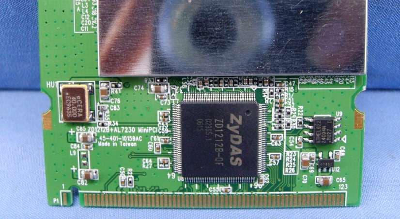
IOU-NWH3054A
Sep 24, 2006IEEE802.11a/g/b NWH3054A WLAN mini-PCI
Equipment Class
DTS - Digital Transmission System
IOU3050S01
Feb 26, 2004802.11g+ MiniPCI Module
Equipment Class
DTS - Digital Transmission System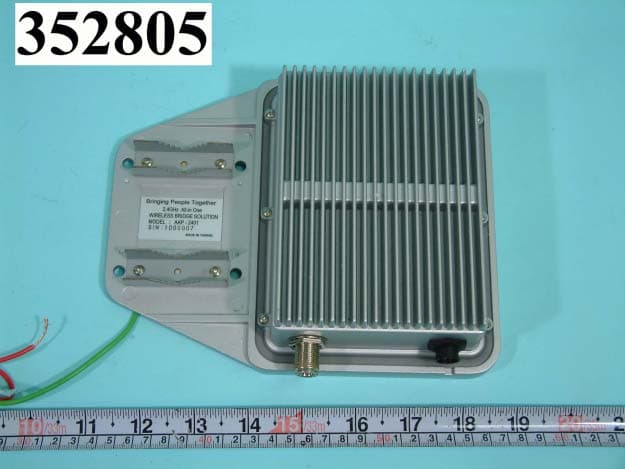
IOU9210S01
Sep 10, 2003OUTDOOR BRIDGE
Equipment Class
DTS - Digital Transmission System
IOU1022S01
Oct 30, 200222Mbps Cardbus Adapter
Equipment Class
DTS - Digital Transmission System
IOU1010S01
Mar 21, 2002Wireless PC Card
Equipment Class
DTS - Digital Transmission System