IWC-DTS2.4GHz Proprietary Radio Module
Noraxon USA Inc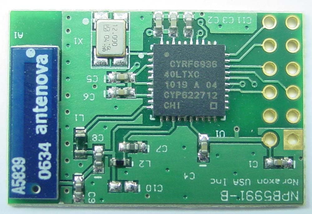
Click to zoom
Application Details
- Equipment Class
- DTS - Digital Transmission System
- Date of Grant
- Oct 05, 2010
- Application Purpose
- Original Equipment
- Date of Application
- Sep 22, 2010
- Equipment Note
- 2.4GHz Proprietary Radio Module
- Frequency Range
- 2402.70000000 - 2477.70000000
- Company
- Noraxon USA Inc
- Country
- United States
Documents & Files
Document Text
Text extracted from the exhibit documents filed with the FCC. Open a document above to read the original.
Cover Letter(s)
7/15/2010 Nemko USA Inc. 11696 Sorrento Valley Rd San Diego, CA USA Attn: Director of Certification FCC ID: IWC-DTS Authority to Act as Agent On our behalf, I appoint Alan Laudani of Nemko USA Inc., 11696 Sorrento Valley Rd, San Diego, CA, USA to act as our agent in the preparation of this application for equipment certification. I certify that submitted documents properly describe the device or system for which equipment certification is sought. I also certify that each unit manufactured, imported or marketed, as defined in Federal Communication Commission’s regulations will have affixed to it a label identical to that submitted for approval with this application. For instances where our authorized agent signs the application for certification on our behalf, I acknowledge that all responsibility for complying with the terms and conditions for certification, as specified by Nemko USA Inc, still resides with Noraxon U.S.A., Inc., 13430 N Scottsdale Rd, Suite 104, Scottsdale AZ, 85254, expiring 1/15/2011. Sincerely, Frank Hosner Technical Director Noraxon U.S.A., Inc. Telemetry • Fixed Cable • Biofeedback • Research • Clinical • EMG Software 13430 North Scottsdale Road • Suite 104 • Scottsdale, Arizona 85254 • Tel: 480-443-3413 • Toll Free: 1-800-364-8985 Fax: 480-443-43-27 • Email: [email protected] • Website: http://www.noraxon.com
Cover Letter(s)
7/15/2010 Nemko USA Inc. 11696 Sorrento Valley Rd San Diego, CA USA Re: Request of Confidentiality for FCC ID#: IWC-DTS Model: 599 Pursuant to Sections 0.457(d)(I)(ii) and 0.459 of the Commission’s Rules, the Applicant hereby requests confidential treatment of information accompanying as outlined below: Schematics, Parts List, Technical Description, Block Diagrams and Installation Instructions. The above materials contain trade secrets and proprietary information not customarily released to the public. The public disclosure of these matters might be harmful to the Applicant and provide unjustified benefits to its competitors. The installation manual is very technical and is not provided to the consumer because the consumer cannot service the device, nor is the consumer receiving the installation manual. The Applicant understands that pursuant to Rule 0.457(d)(I)(ii), disclosure of this Application and all accompanying documentation will not be made before the date of the Grant for this Application. Sincerely, Frank Hosner Technical Director Noraxon U.S.A., Inc. Telemetry • Fixed Cable • Biofeedback • Research • Clinical • EMG Software 13430 North Scottsdale Road • Suite 104 • Scottsdale, Arizona 85254 • Tel: 480-443-3413 • Toll Free: 1-800-364-8985 Fax: 480-443-43-27 • Email: [email protected] • Website: http://www.noraxon.com
Cover Letter(s)
Telemetry • Fixed Cable • Biofeedback • Research • Clinical • EMG Software 13430 North Scottsdale Road • Suite 104 • Scottsdale, Arizona 85254 • Tel: 480-443-3413 • Toll Free: 1-800-364-8985 Fax: 480-443-43-27 • Email: [email protected] • Website: http://www.noraxon.com August 19, 2010 Nemko USA Inc. 11696 Sorrento Valley Rd San Diego, CA USA FCC: IWC-DTS IC: 9113A-DTS Modular Approval Requirements Limited Modular Approval is being requested for this device. The module meets all of the technical specifications applicable to the frequency band of operation. The module has its own RF shielding. The module contains an internal shield. The shielding is achieved by the ground plane on the bottom layer of the module as well as the die and substrate ground. This shielding prevents RF coupling between the RF circuitry of the module and any wires or circuits in the device into which the module is installed. In addition the traces are kept very short to minimize undesirable radiation. See the “PCB Layout.pdf” document for ground plane details. All modulation and data input(s) are buffered. Data to the modulation circuit is buffered on the module via the WirelessUSB integrated circuit. Refer to the information regarding the on-board SERDES provided with the file “Technical Description.pdf”. The module has its own power supply regulation and local reference oscillator. The remote module contains its own power supply regulation and the rf reference oscillator is contained within the module (reference 12 MHz oscillator X1). Power supply regulation is provided within the WirelessUSB integrated circuit that regulates the control voltage to the rf and data circuits. Details of clocking and power management are contained in the document “Technical Description.pdf”. The modular transmitter must comply with the antenna requirements of Section 15.203 and 15.204(c). The certification submission contains a detailed description of the configuration of all antennas that will be used with the module. The remote module uses a 4.1dBi Chip Antenna that will be internal to the end-products into which this module is installed. For Industry Canada, the module meets certification labeling requirements. Host devices that contain separately certified modules do not need to be re-certified, provided that they meet the following conditions: Telemetry • Fixed Cable • Biofeedback • Research • Clinical • EMG Software 13430 North Scottsdale Road • Suite 104 • Scottsdale, Arizona 85254 • Tel: 480-443-3413 • Toll Free: 1-800-364-8985 Fax: 480-443-43-27 • Email: [email protected] • Website: http://www.noraxon.com • The host device, as a stand alone unit without any separately certified modules, complies with all applicable Radio Standards Specifications. • The host device and all the separately certified modules it contains jointly meet the safety requirements of RSS-102, if applicable. • The host device complies with the certification labeling requirements of each of the modules it contains. The module is appropriately labeled (refer to the label and label location drawings contained within this application). For the FCC, the modular transmitter must be tested in a stand-alone configuration, i.e., the module must not be inside another device during testing. This is intended to demonstrate that the module is capable of complying with Part 15 emission limits regardless of the device into which it is eventually installed. Unless the transmitter module will be battery powered, it must comply with the AC line conducted requirements found in Section 15.207. Test data contained in this application is for the device tested as a stand-alone device. Radiated spurious emissions data demonstrating compliance with the requirements of Part 15 of the FCC rules for intentional radiators has been provided. Note that these tests were performed with no shield on the device to demonstrate compliance with the relevant limits. For the FCC, the modular transmitter must be labeled with its own FCC ID number, and, if the FCC ID is not visible when the module is installed inside another device, then the outside of the device into which the module is installed must also display a label referring to the enclosed module. This exterior label can use wording such as the following: “Contains Transmitter Module FCC ID: XYZMODEL1” or “Contains FCC ID: XYZMODEL1.” The module is appropriately labeled (refer to the label and label location drawings contained within this application The modular transmitter must comply with any applicable RF exposure requirements. The module meets the requirements for a portable device that may be used at separation distances of less than 2.5cm from the human body because its output power is below the threshold of 60/fGHz mW (25mW for a 2.4GHz device). Installation and operation of this device is limited to Noraxon U.S.A., Inc only. Sincerely, Frank Hosner Technical Director Noraxon U.S.A., Inc
Cover Letter(s)
PROPRIETARY INFORMATION AGREEMENT Date: This agreement is between: Noraxon U.S.A., Inc. (Noraxon below) 13430 N Scottsdale Rd, Suite 104 Scottsdale, AZ 85254 Noraxon Employee Purpose: Noraxon and the employee/contractor intend to install and test Noraxon’s products or technology. During the course of that product, the Noraxon may provide Proprietary Information to the employee/contractor Accordingly, Noraxon agrees that: 1 - “Proprietary Information” means documents, samples or other material (including machine-readable or interpreted material and artwork) containing information such as, but not limited to, technical data or knowledge, that the Noraxon considers proprietary or confidential and which is strictly necessary for the above stated Purpose. 2 - The employee/contractor will protect such Proprietary Information against disclosure to others for a period of five years from receipt with the same care the Noraxon protects its own Proprietary Information of a similar nature. 3 - This agreement does not apply to documents or material containing only information that is or becomes publicly known without fault of the recipient, or is or becomes lawfully available from another source, or was known to the recipient before receipt from the provider, or is independently developed by the recipient. On behalf of Noraxon USA, On behalf of (employee/contractor) _____________________________________ ________________________________________ Signature, Signature, Frank Hosner Engineering Manager (employee/contractor contact title)
External Photos
DTS Radio Module Photos
ID Label/Location Info
FCC ID: IWC-DTS IC: 9113A-DTS TeleMyo DTS Radio Module FCC/IC Label 0.6 in 0.3 in Substrate Material: Vinyl, White Ink Color: Black Model: 599
Internal Photos
DTS Radio Module Photos
RF Exposure Info
Evaluation of MPE limit at a given distance Equation from page 18 of OET Bulletin 65, Edition 97-01where: S = power density P = power input to the antennaG = power gain of the antenna in the direction of interest relative to an isotropic radiatorR = distance to the center of radiation of the antenna Maximum peak output power --Conducted 2.12 dBm 0.002 (W) Antenna gain(typical): 4.40 (dBi) Maximum antenna gain: 2.75 (numeric) Evaluation distance: 20.00 (cm) Evaluation frequency: 2441.70 (MHz) Limit from table below: 1 (mW/cm^2) Power density at Evaluation frequency: 0.00089 (mW/cm^2) EUT complies FCC/LSGAC Local Official’s Guide to RFA LOCAL GOVERNMENT OFFICIAL'S GUIDE TO TRANSMITTING ANTENNA RFEMISSION SAFETY: RULES, PROCEDURES, AND PRACTICAL GUIDANCE 2 4 R PG S π =
Test Report
Nemko USA, Inc. 11696 Sorrento Valley Road, Suite F, San Diego, CA 92121 Phone (858) 755-5525 Fax (858) 452-1810 DATE DOCUMENT NAME DOCUMENT # PAGE July 29, 2010 TeleMyo-DTS Certification Test Report FCC ID: IWC-DTS IC: 9113A-DTS 2010 07153601 FCC 1 of 33 CERTIFICATION TEST REPORT P ART 15.247C For The Transmitter Module Model: 599 FCC ID: IWC-DTS IC: 9113A-DTS PREPARED FOR: Noraxon USA 13430 Nort Scottsdale Road, Suite 104 Scottsdale, AZ 85254 Prepared on: July 29, 2010 Report Number: 2010 07153601 FCC Project Number: 47002-1 NEx Number: 153601 Total Pages: 33 Nemko USA, Inc. 11696 Sorrento Valley Road, Suite F, San Diego, CA 92121 Phone (858) 755-5525 Fax (858) 452-1810 DATE DOCUMENT NAME DOCUMENT # PAGE July 29, 2010 TeleMyo-DTS Certification Test Report FCC ID: IWC-DTS IC: 9113A-DTS 2010 07153601 FCC 2 of 33 DOCUMENT HISTORY REVISION DATE COMMENTS - July 29, 2010 Prepared By: A. Laudani - July 29, 2010 Initial Release: Alan Laudani NOTE: Nemko USA, Inc. hereby makes the following statements so as to conform to Chapter 10 (Test Reports) Requirements of ANSI C63.4 (2003) “Methods and Measurement of Radio-Noise Emissions from Low- Voltage Electrical and Electronic Equipment in the Range of 9 kHz to 40 GHz”: o The unit described in this report was received at Nemko USA, Inc.'s facilities on July 8, 2010. o Testing was performed on the unit described in this report on July 26, 2010 to July 28, 2010. o The Test Results reported herein apply only to the Unit actually tested, and to substantially identical Units. o This report does not imply the endorsement of the Federal Communications Commission (FCC), Industry Canada, NVLAP or any other government agency. This Report is the property of Nemko USA, Inc., and shall not be reproduced, except in full, without prior written approval of Nemko USA, Inc. However, all ownership rights are hereby returned unconditionally to Noraxon USA, and approval is hereby granted to Noraxon USA, and its employees and agents to reproduce all or part of this report for any legitimate business purpose without further reference to Nemko USA, Inc. Nemko USA, Inc. 11696 Sorrento Valley Road, Suite F, San Diego, CA 92121 Phone (858) 755-5525 Fax (858) 452-1810 DATE DOCUMENT NAME DOCUMENT # PAGE July 29, 2010 TeleMyo-DTS Certification Test Report FCC ID: IWC-DTS IC: 9113A-DTS 2010 07153601 FCC 3 of 33 TABLE OF CONTENTS DOCUMENT HISTORY.....................................................................................................................................2 CERTIFICATION................................................................................................................................................4 1. ADMINISTRATIVE DATA AND TEST SUMMARY..........................................................................5 1.1. ADMINISTRATIVE DATA............................................................................................................................5 2. TEST SUMMARY ....................................................................................................................................6 3. SYSTEM CONFIGURATION.................................................................................................................7 3.1. DESCRIPTION AND METHOD OF EXERCISING THE EUT..............................................................................7 3.2. SYSTEM COMPONENTS AND POWER CABLES.............................................................................................7 3.3. DEVICE INTERCONNECTION AND I/O CABLES...........................................................................................8 3.4. DESIGN MODIFICATIONS FOR COMPLIANCE..............................................................................................8 3.5. TECHNICAL SPECIFICATIONS OF THE EUT.................................................................................................8 4. DESCRIPTION OF TEST SITE AND ENVIRONMENT ....................................................................9 4.1. DESCRIPTION OF TEST SITE.......................................................................................................................9 4.2. DEVIATIONS FROM LABORATORY TEST PROCEDURES..............................................................................9 4.3. MODIFICATIONS PERFORMED DURING ASSESSMENT.................................................................................9 4.4. RECORD OF TECHNICAL JUDGEMENTS......................................................................................................9 4.5. EUT PARAMETERS AFFECTING COMPLIANCE...........................................................................................9 4.6. TEST DELETED..........................................................................................................................................9 4.7. ADDITIONAL OBSERVATIONS....................................................................................................................9 4.8. TEST ENVIRONMENT.................................................................................................................................9 5. DESCRIPTION OF TESTING METHODS.........................................................................................10 5.1. INTRODUCTION........................................................................................................................................10 5.2. CONFIGURATION AND METHODS OF MEASUREMENTS FOR CONDUCTED EMISSIONS...............................10 5.3. CONFIGURATION AND METHODS OF MEASUREMENTS FOR FREQUENCY IDENTIFICATION.......................10 5.4. CONFIGURATION AND METHODS OF MEASUREMENTS FOR RADIATED EMISSIONS..................................11 6. TEST RESULTS......................................................................................................................................12 6.1. CONDUCTED EMISSIONS......................................................................…
Text truncated - open the document above for the full version.
Test Setup Photos
Conducted Emissions Radiated Emissions On Edge On End On back
Contact Information
Applicant
Dave Byman(Technical Director)
Technical Contact
Noraxon U.S.A., Inc.Dave Byman
[email protected]480-443-3413
13430 N Scottsdale Rd, Suite 104 · Scottsdale, Arizona · United States
Non-Technical Contact
Noraxon U.S.A., Inc.Dave Byman
[email protected]480-443-3413
Test Firm
Nemko USA, Inc. - San Diego EMC DivisionJan Blomgren
[email protected]760-444-3500
Technical Specifications
| # | Rule Parts | Frequency Range | Power Output |
|---|---|---|---|
| 1 | 15C | 2.40 GHz - 2.48 GHz | 2.00 mW |
Other Applications from Noraxon USA Inc
IWC-TELEMYO-R
Mar 16, 1994Telemetry Receiver A ferrite-loaded analog output cable must be provided with each unit.
Equipment Class
CYY - Communications Receiver used w/Pt 15 TransmitterIWC-TELEMYO-T1
Mar 16, 1994Telemetry Transmitter
Equipment Class
DXX - Part 15 Low Power Communication Device TransmitterIWCTELEMY08R
May 15, 1991UHF Data Receiver
Equipment Class
CXX - Communications Rcvr for use w/ licensed Tx and CBsIWCTELEMY08
Mar 28, 1991TNB - Licensed Non-Broadcast Station Transmitter
Equipment Class
TNB - Licensed Non-Broadcast Station Transmitter