IYF2CH900-2727 MHz R/C TRANSMITTER
Hobbico Inc
Click to zoom
Application Details
- Equipment Class
- DXX - Part 15 Low Power Communication Device Transmitter
- Date of Grant
- Jul 21, 2004
- Application Purpose
- Original Equipment
- Date of Application
- Jul 21, 2004
- Equipment Note
- 27 MHz R/C TRANSMITTER
- Frequency Range
- 26.96000000 - 27.28000000
- Company
- Hobbico Inc
- Country
- United States
Documents & Files
Document Text
Text extracted from the exhibit documents filed with the FCC. Open a document above to read the original.
Users Manual
R/C MicroCycles are recommended for ages 8 and older. To ensure the safety and fun of young modelers, please follow these operating instructions and general safety rules: •Adult supervision is recommended. •Do not allow children under age 3 to play with the R/C MicroCycles or radio transmitter. Small parts could be swallowed and cause suffocation. •Do not pick up your R/C MicroCycles when it is in motion. Keep hair, loose clothing, face and fingers away from the tires and wheels. •R/C MicroCycles are for indoor use only, and may be permanently damaged by outdoor dirt and dust. •Do not run your R/C MicroCycles on rugs or carpeting. The fibers may become tangled in and damage the model. •Never charge, run, or store your R/C MicroCycles in areas of high temperatures, low temperatures, or high humidity. Do not store in direct sunlight. •Never operate your model in any area with full-size vehicles. •Moisture can cause electronic malfunction and short circuits with strong electrical current. Should your model become wet, stop using it immediately. •Never disassemble or solder the model. Do not put it into fire. •Do not drop your model from high places. This device complies with Part 15 of the FCC rules. Operation is subject to the following two conditions: (1) This device may not cause harmful interference, and (2) this device must accept interference received, including interference that may cause undesired operation. The manufacturer is not responsible for any radio or TV interference caused by unauthorized modifications to this equipment. Such modifications could void the user’s authority to operate the equipment. Meets Canada 210 requirements. Motorcycle Battery CareTransmitter Battery Care Always use “AA” alkaline batteries. If improper batteries are used in the transmitter, they may become hot, leak, and rupture. Follow these precautions: Four “AA” alkaline batteries are required. Never use other types of batteries. 1.Remove the battery cover screw with a Phillips screwdriver. 2.Install your batteries with the correct polarity. 3.Replace the battery cover and tighten the screw. A rechargeable battery is built into the main body of the motorcycle. Using the battery incorrectly will cause it to leak, rupture, or ignite. Follow these precautions: •If your R/C MicroCycle has been unused for a long period or you are charging its built-in battery for the first time, the battery may not charge to full capacity. This does not indicate battery failure. Recharging and running the model 4 or 5 times will gradually lengthen run times. •Fully discharge the battery by running the motorcycle before recharging. •Charge the battery only when the motorcycle is NOT running. To prevent overcharging, never recharge a battery which has already been fully charged. This will not increase running speed. •Recharge the battery only with the transmitter’s built-in charger. •If the chassis becomes warm, let it cool before running again. •Never use rechargeable batteries, such as NiCds, in the transmitter. •Do not mix different types of batteries, or old and new batteries. •When changing batteries, replace ALL of the old batteries with new ones. •Make sure the batteries are installed with the correct polarity as shown in the battery compartment. •Do not charge or disassemble your transmitter batteries. Never allow them to become hot or to burn. To avoid short-circuits, avoid getting them wet. •If liquid from inside the batteries contacts your skin or clothes, wash them with water. If leaked battery fluid gets into your eyes, flush them immediately with cool water and seek medical attention. Do not rub eyes. •You can race about 50 times with new “AA” alkaline batteries. Transmitter Battery Installation This product uses a recyclable NiCd battery. To dispose of the battery, remove it and take it to a recycling center. Entire Contents © Copyright 2004 – 3033140 Printed in China TM How to Charge How to Race Troubleshooting GENERAL SAFETY PRECAUTIONS BATTERY HANDLING AND CARE Position the motorcycle with the front-end facing the same direction as the antenna on the transmitter. Snap your model onto the built-in charger. The metal contacts on the motorcycle and the charger must make contact. While charging, keep pressing the motorcycle against the transmitter and make sure the CHARGE light is on. The charge light on the front of the transmitter will light for 45 seconds. When it goes out, the battery has completed charging. Gently pull up the antenna on the transmitter. Turn on the MicroCycle at the rear of the motorcycle. Place on hard, smooth surface and be prepared for fast action! Steer the front tire left or right by pushing the directional toggle control. 2 3 4 1 2 3 4 1 2 1 ☞ To race, each car must be on a different frequency. offon 2 4 ON/OFF SWITCH Turn the MicroCycle off at the rear of the motorcycle. Gently push the antenna back into the transmitter. After Racing ® Motorcycle does not run Probable Cause:Transmitter battery capacity is low, or batteries have not been installed. Probable Cause:Radio signals don’t seem to reach the motorcycle. Correction:Install four brand- new “AA” alkaline batteries (they must be alkaline). Correction:Fully extend the antenna on the motorcycle and transmitter. Maximum range is 10-15 feet. Motorcycle does not operate properly Probable Cause:Are you driving your motorcycle on a rug? Probable Cause:Is there dust and/or lint on the tires? Correction:R/C MicroCycles are not intended for running on rugs or carpets. Correction:Remove dust/lint from the tires. Motorcycle moves uncontrollably Probable Cause:Interference from reflected radio waves Probable Cause:Are you running with another motorcycle on the same frequency? Correction:Tu r n o ff electronic devices or move to a different location. Correction:Each motorcycle must be on a different frequency. R/C MicroSizers MicroCycles HCAC0991-0996 Te s t e d To Comply With FCC Standards FOR HOME OR OFFICE USE
Test Report
TIMCO ENGINEERING INC. 849 NW State Road 45 Newberry, Florida 32669 http://www.timcoengr.com 888.472.2424 F 352.472.2030 email: [email protected] APPLICANT: HOBBICO INC. FCC ID: IYF2CH900-27 REPORT #: H\HOBBICO\1018ZUT4\1018ZUT4TestReport.doc COVER SHEET Test Report Product Name: R/C TRANSMITTER FCC ID: IYF2CH900-27 Applicant: HOBBICO INC. 2904 RESEARCH ROAD CHAMPAIGN IL 61821 Date Receipt: JULY 15, 2004 Date Tested: JULY 16, 2004 TIMCO ENGINEERING INC. 849 NW State Road 45 Newberry, Florida 32669 http://www.timcoengr.com 888.472.2424 F 352.472.2030 email: [email protected] APPLICANT: HOBBICO INC. FCC ID: IYF2CH900-27 REPORT #: H\HOBBICO\1018ZUT4\1018ZUT4TestReport.doc TABLE OF CONTENTS TABLE OF CONTENTS LIST APPLICANT: HOBBICO INC. FCC ID: IYF2CH900-27 TEST REPORT CONTAINING: PAGE 1...............TEST EQUIPMENT LIST PAGE 2...............TEST PROCEDURE PAGE 3...............RADIATION INTERFERENCE TEST DATA PAGE 4...............OCCUPIED BANDWIDTH PAGE 5...............OCCUPIED BANDWIDTH PLOT EXHIBITS INCLUDING: BLOCK DIAGRAM SCHEMATIC INSTRUCTION MANUAL LABEL SAMPLE LABEL LOCATION EXTERNAL PHOTOGRAPHS INERNAL PHOTOGRAPHS OPERATIONAL DESCRIPTION TEST SET UP PHOTOGRAPHS TIMCO ENGINEERING INC. 849 NW State Road 45 Newberry, Florida 32669 http://www.timcoengr.com 888.472.2424 F 352.472.2030 email: [email protected] APPLICANT: HOBBICO INC. FCC ID: IYF2CH900-27 REPORT #: H\HOBBICO\1018ZUT4\1018ZUT4TestReport.doc Page 1 of 5 EMC Equipment List Device Manufacturer Model Serial Number Cal/Char Date Due Date 3/10-Meter OATS TEI N/A N/A Listed 3/27/04 3/26/07 3-Meter OATS TEI N/A N/A Listed 1/13/03 1/12/06 Biconnical Antenna Eaton 94455-1 1057 CAL 3/18/03 3/18/05 Biconnical Antenna Eaton 94455-1 1096 CAL 10/1/01 10/1/03 Biconnical Antenna Electro- Metrics BIA-25 1171 CAL 4/26/01 4/26/03 Blue Tower Quasi-Peak Adapter HP 85650A 2811A01279 CAL 4/15/03 4/15/05 Blue Tower RF Preselector HP 85685A 2620A00294 CAL 4/27/04 4/27/06 Blue Tower Spectrum Analyzer HP 8568B 2928A04729 2848A18049 CAL 4/15/03 4/15/05 LISN Electro- Metrics ANS-25/2 2604 CAL 10/9/01 10/9/03 LISN Electro- Metrics EM-7820 2682 CAL 3/12/03 3/12/05 Log- Periodic Antenna Eaton 96005 1243 CAL 5/8/03 5/8/05 TIMCO ENGINEERING INC. 849 NW State Road 45 Newberry, Florida 32669 http://www.timcoengr.com 888.472.2424 F 352.472.2030 email: [email protected] APPLICANT: HOBBICO INC. FCC ID: IYF2CH900-27 REPORT #: H\HOBBICO\1018ZUT4\1018ZUT4TestReport.doc Page 2 of 5 TEST PROCEDURE GENERAL: This report shall NOT be reproduced except in full without the written approval of TIMCO ENGINEERING, INC. RADIATION INTERFERENCE: The test procedure used was ANSI STANDARD C63.4- 1992 using a HEWLETT PACKARD spectrum analyzer with a pre-selector. The bandwidth of the spectrum analyzer was 100 kHz with an appropriate sweep speed. The analyzer was calibrated in dB above a microvolt at the output of the antenna. The resolution bandwidth was 100 kHz and the video bandwidth was 300 kHz. The ambient temperature of the UUT was 80ºC with a humidity of 76%. FORMULA OF CONVERSION FACTORS: The Field Strength at 3m was established by adding the meter reading of the spectrum analyzer (which is set to read in units of dBuV) to the antenna correction factor supplied by the antenna manufacturer. The antenna correction factors are stated in terms of dB. The gain of the Pre-selector was accounted for in the Spectrum Analyzer Meter Reading. Example: Freq (MHz) METER READING + ACF = FS 33 20 dBuV + 10.36 dB = 30.36 dBuV/m @ 3m ANSI STANDARD C63.4-1992 10.1.7 MEASUREMENT PROCEDURES: The unit under test was placed on a table 80 cm high and with dimensions of 1m by 1.5m. The table used for radiated measurements is capable of continuous rotation. When an emission was found, the table was rotated to produce the maximum signal strength. At this point, the antenna was raised and lowered from 1m to 4m. The antenna was placed in both the horizontal and vertical planes. TIMCO ENGINEERING INC. 849 NW State Road 45 Newberry, Florida 32669 http://www.timcoengr.com 888.472.2424 F 352.472.2030 email: [email protected] APPLICANT: HOBBICO INC. FCC ID: IYF2CH900-27 REPORT #: H\HOBBICO\1018ZUT4\1018ZUT4TestReport.doc Page 3 of 5 APPLICANT: HOBBICO INC. FCC ID: IYF2CH900-27 NAME OF TEST: RADIATION INTERFERENCE RULES PART NO.: 15.227 REQUIREMENTS: CARRIER FREQUENCY WILL NOT EXCEEDS 80 dBuV/m AT 3M. OUT-OF-BAND EMISSIONS SHALL NOT EXCEED: 30 - 88 MHz 40.0 dBuV/M MEASURED AT 3 METERS 88 - 216 MHz 43.5 dBuV/M 216 - 960 MHz 46.0 dBuV/m ABOVE 960 MHz 54.0 dBuV/m TEST DATA: Emission Frequency MHz Meter Reading dBuV Ant. Polarity Coax Loss dB Correction Factor dB Field Strength dBuV/m Margin dB 27.20 56.0 V 6.93 11.99 74.92 5.08 54.30 28.8 V 1.11 9.42 39.33 0.67 81.40 18.0 V 1.21 8.70 27.91 12.09 108.60 20.6 V 1.44 10.97 33.01 10.49 135.60 15.0 V 1.71 14.82 31.53 11.97 SAMPLE CALCULATION: FSdBuV/m = MR (dBuV) + ACFdB. TEST PROCEDURE : The procedure used was ANSI STANDARD C63.4-1992. The spectrum was scanned from 30 MHz to 1000 MHz. When an emission was found, the table was rotated to produce the maximum signal strength. The antenna was placed in both the horizontal and vertical planes and the worse case emissions were reported. The UUT was tested in 3 orthogonal planes. TEST RESULTS: THE UNIT DOES MEET THE FCC REQUIREMENTS. PERFORMED BY: MARIO R. de ARANZETA DATE: JULY 16, 2004 TIMCO ENGINEERING INC. 849 NW State Road 45 Newberry, Florida 32669 http://www.timcoengr.com 888.472.2424 F 352.472.2030 email: [email protected] APPLICANT: HOBBICO INC. FCC ID: IYF2CH900-27 REPORT #: H\HOBBICO\1018ZUT4\1018ZUT4TestReport.doc Page 4 of 5 APPLICANT: HOBBICO INC. FCC ID: IYF2CH900-27 NAME OF TEST: Occupied Bandwidth RULES PART NO.: 15.227 REQUIREMENTS: The field strength of any emissions appearing between the band edges and up to 10 kHz above and below the band edges shall be attenuated to the general limits of 15.209. TEST DATA: THE GRAPH ON THE FOLLOWING PAGE REPRESENTS THE EMISSIONS TAKEN FOR OCCUPIED BANDWIDHT FOR THIS D…
Text truncated - open the document above for the full version.
Contact Information
Applicant
Neal Cloud(Senior Product Manager)
Test Firm
Timco Engineering, Inc.S Sanders
Technical Specifications
| # | Rule Parts | Frequency Range | Power Output |
|---|---|---|---|
| 1 | 15C | 26.96 MHz - 27.28 MHz | - |
Other Applications from Hobbico Inc
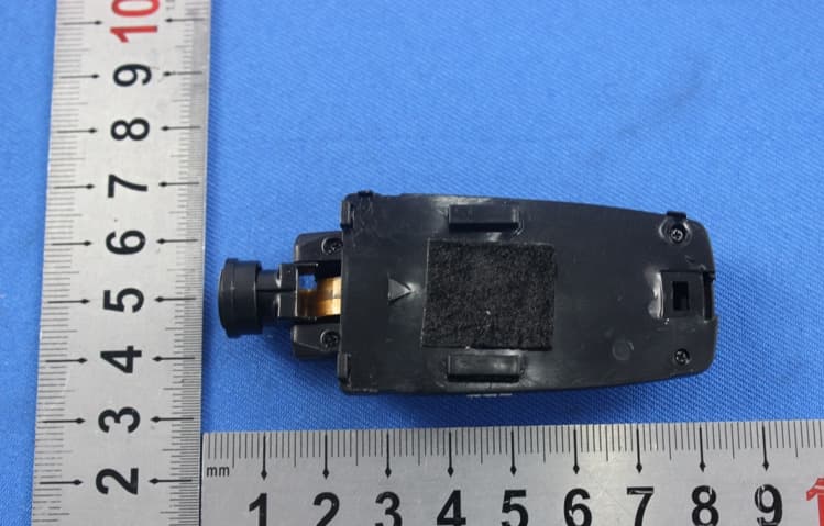
IYFZ1000
Oct 08, 2015wifi module (only for the camera)
Equipment Class
DTS - Digital Transmission System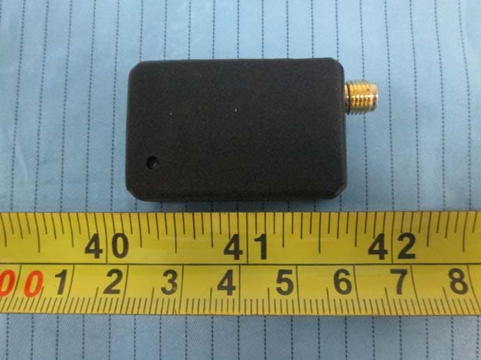
IYFFPVT1
Sep 28, 2015Tactic FPV-T1 5.8GHz 25mW Transmitter
Equipment Class
DXX - Part 15 Low Power Communication Device Transmitter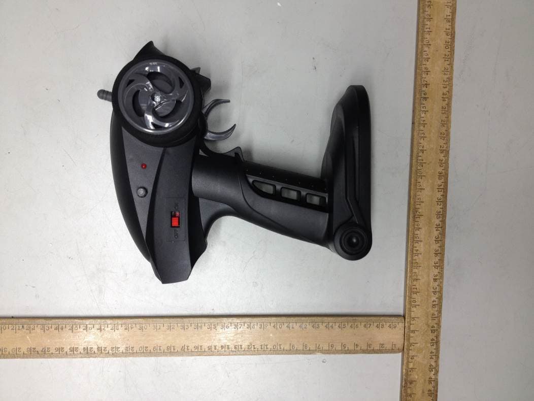
IYFRVLC01
Sep 08, 2015Radio Control Toy Transmitter (2.4GHz)
Equipment Class
DXX - Part 15 Low Power Communication Device Transmitter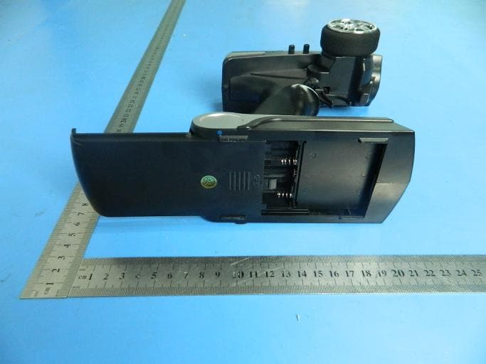
IYFDIDJ1001
Aug 28, 2015D103
Equipment Class
DSS - Part 15 Spread Spectrum Transmitter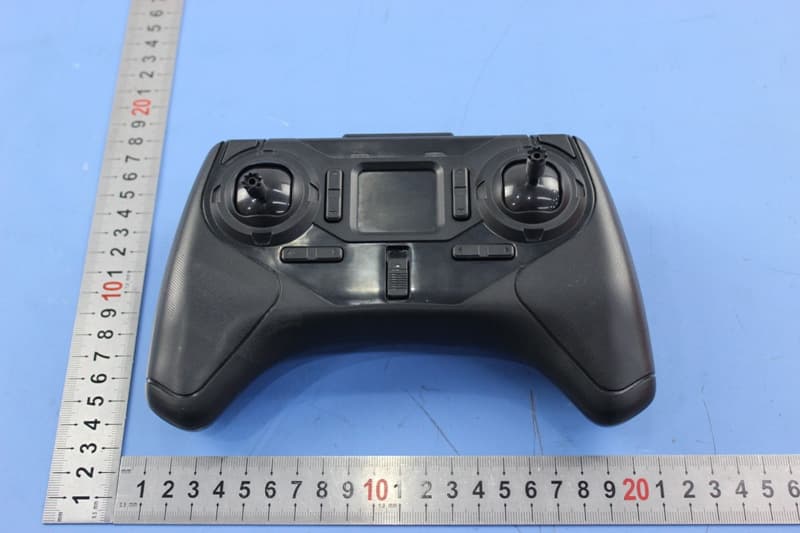
IYFMR100
Jul 01, 2015Radio controlled model quadcopter and transmitter/receiver
Equipment Class
DXX - Part 15 Low Power Communication Device Transmitter